WONDER: model and experiments with a CORBA Based Architecture for Large Scale Workflow. Roberto Silveira Silva Filho, Jacques Wainer, Edmundo R. M. Madeira IC -Institute of Computing UNICAMP - University of Campinas 13083-970 Campinas - SP - Brazil robsilfi, wainer,
[email protected] Abstract Standard client-server workflow management systems have an intrinsic scalability limitation, the central server, which represents a bottleneck for large-scale applications. This server is also a single failure point that may disable the whole system. We propose a fully distributed architecture for workflow management systems. It is based on the idea that the case (an instance of the process) migrates from host to host, following a process plan, while the case activities are executed. This basic architecture is improved so that other requirements for Workflow Management Systems, besides scalability, are also contemplated. A CORBA-based implementation of such architecture is discussed, with its limitations, advantages and project decisions described. This paper presents the experiments performed using the WONDER architecture, analyzing its overhead and scalability under an increasing number of cases, and an increasing volume of data exchanged. Keywords Large-scale Workflow, Distributed Objects, CORBA, Distributed Systems, and Mobile Objects.
1. Introduction Workflow Management Systems (WFMSs) are used to coordinate and sequence business processes, such as loan approval, insurance reimbursement, and other office procedures. These processes are represented as workflows, computer interpretable description of activities (or tasks), and their execution order. The workflow also describes the data available and generated by each activity, parallel activities, synchronization points and so on. This description may also express constrains and conditions such as when the activities should be executed, a specification of who can or should perform each activity, and which tools and programs are needed during the activity execution
[1]. Many research prototypes and commercial WFMSs are based on the standard client-server architecture defined by the WFMC (Workflow Management Coalition) [2]. In such systems, the Workflow Engine, the core of a WFMS, is executed in a server machine that typically stores both the application data ( the data that is used and generated by each activity within the workflow), and the workflow data (comprising its definition, the state and history information about each instance of the workflow, and any other information related to its execution). Recently, there has been a surge on research prototypes that are not centralized, but distributed to different degrees. There are many issues that motivate the the distributed WFMS architecture research. First, it is assumed that the centralized nature of standard WFMS will present a bottleneck for large-scale systems. The centralized storage of application and workflow data, and the centralized interpretation of the workflow are also a single failure point that may severely paralyze the whole system and the whole business. Finally, workflow execution is itself a clear example for distributed systems: not only the execution of the activities are inherently distributed, because they are executed by users working on personal machines, but organizations are becoming more and more geographically dispersed. The business processes are also distributed in at least two senses. First the same process, say office supplies purchase, may be executed in different branches of the organization, and second a hiring process, for instance, may start in a branch and continue in other branches before it comes to a conclusion. It is reasonable for organizations to expect a distributed execution of each of these two processes, instead of relying on a worldwide network that would connect each branch to a central computing facility. This research presents a radically distributed architecture for WFMS in comparison with other proposed architectures. In the WONDER, (Workflow ON Distributed EnviRonment), the granularity of the distributed objects
1
are the finer we are aware of. Moreover, the WONDER system addresses requirements and specifications that some of the other distributed architectures have not address. We will discuss these requirements and their impact on the architecture as follows.
1.1. Terms We will use, from now on, the following definitions. A process definition, or a plan, is described in terms of the WFMC primitives: sequencing, and-join, and-split, orjoin, and or-split [2]. A case is an instance of a process. Thus, if purchase of office supplies is a process, then Joe’s Friday request to purchase 200 paper clips is a case. Processes are defined in terms of activities or tasks, which are atomic actions performed by a single person or by a program. Role is the generic description of a set of abilities required to a person in order to perform an activity. Thus, secretary, programmer and reviewer are roles. People or programs that perform the activities are called users or actors. A particular user can perform many roles. If the user is a person she has a preferential host, a computer to where all her work related notifications and activities are send. In particular, the notifications are send to her task list.
1.2. Requirements for Workflow Systems In this paper, we will address the following requirements of a WFMS: • Scalability: The WFMS should not have its performance degraded due to the increase of: processes, cases or activity instances within a workflow. It should also support a big volume of application data and actors. • Failure recovery: The WFMS should deal with both, software and hardware failures with the least intervention of users. • Availability: The WFMS must not get unavailable/unreachable for long periods of time. • Monitoring: The WFMS should be able to provide information about the current state of all cases and activities in execution. • Traceability: The WFMS should be able to provide the history (trace) information of the current and terminated cases. • Late binding (of executors): Standard workflow specifications should allow for some late binding, as to allow for more generic and thus useful descriptions. The most common late binding in WFMS is the executor binding: workflow definitions usually does not specify who will perform an activity, but instead allow the description of a set of potential ac-
tors, which will only be determined at execution time. Thus, instead of saying that John must perform activity A, one can specify in the workflow that a programmer must perform activity A, and at enactment time, the system will query a data base, retrieve all programmers, and assign the instance of activity A to some of them. Other forms of late binding are possible but not usual. For example, one may bind execution tools, at enactment time, specifying that a text processor must be used for activity A, but leaving the specific decision to the enactment mechanism, that may look at the executor’s preference, or the number of licensed software in execution. We are not aware of any system that allow late binding of execution tools, and we do not consider it in this architecture, although that would not bring any conceptual problem. The WONDER architecture does deal with late binding of executors, which was not dealt with in other distributed architectures. Interface with executors: Users that will execute the activities must have a mechanism to select which activity to execute now, and which to execute later. They must be able to communicate to the system that they are temporarily unavailable and to customize preferences regarding applications, machines in which they execute their activity, and so on. Support for external applications: The execution of a particular activity may require external tools (such as word processors, spreadsheets, CAD systems, expert systems, and so on). The WFMS should be able to start such external applications and determine when these tools have been terminated, in order to manage the data read and produced by these applications.
1.3. Paper Description The next section discusses the main components of the WONDER architecture. Section 3 discusses the project of this architecture using CORBA (Common Object Request Broker Architecture). Section 4 presents the main implementation issues. Section 5 describes some related work and, finally, Section 6 presents some conclusions.
2. The Distributed Model In general, and using informal terms, the WONDER architecture is based on the idea that each case is a mobile agent that migrates from host to host as the case activities are performed. The agent encapsulates both the application data and the plan for that case (workflow control data). The case "moves’’ to a particular user’s host once it
2
"figures out’’ that the next activity will be performed by that user at that host. Once the activity is finished, the agent "figures out’’ another user to perform the next activity and moves to his/her host. This mobile agent architecture copes with the scalability requirement, since there is no central control or data server, and there is no performance bottleneck. The WONDER uses the activity instance granularity, that is, there are as many active, distributed objects, as the number of instances of activities in execution, for all cases. Thus if for the hiring process there are two cases, Jose and Maria’s hiring, and Jose’s process is currently executing the verify-information and verify-securityclearance activities, while Maria’s case is in the explanation-of-benefits activities, then there will be three active objects, representing the activity instances in execution. It may happen that two of those objects are being executed by Chang, and thus usually two of the objects would be executing in Chang’s personal workstation. The architecture uses weak migration of mobile agents. There is no code mobility, only data and the object state are mobile. That is, the architecture presupposes that all the machines that may be involved in the execution of any activity in any of the organization’s processes has a copy of some of the programs of the WONDER architecture. In particular, the program, or object, responsible for controlling the execution of an activity instance is the Activity Manager. Each activity manager coordinates the execution of an activity in each case. When the next activity of a case needs to be performed, a new activity manager is created at the preferential host of the user assigned to that activity. This activity is, then, configured with its specific data, and the previous activity case state. The plan interpretation is resumed and the activity is executed using the appropriate applications, through the use of application wrappers. The activity manager waits until the user finishes and then computes who should execute the next activity (by interpreting the plan that came along with the case state, and by querying the appropriate role coordinator). If the next activity is to be performed by a human actor, the activity manager sends the appropriate information to that user’s task list, notifying the case coordinator that the current activity finished and who is the selected user to perform the next activity. After that, the current activity transfers the case information to the new activity manager.
2.1. Architecture Components Some components were defined in order to deal with further requirements. This section discusses each one in turn, and the requirements that they fulfill.
2.1.1. Late Binding - Role Coordinator As mentioned in section 1.2, it is desirable that a WFMS allows the late binding of activities and executors. In standard workflow specifications, this late binding is mediated by the concept of role. Role is a description of the people that can execute that activity and which will only be defined at enactment time. In order to cope with this requirement, it was defined a Role Coordinator component. There are as many role coordinators as there are roles defined in all processes of an organization. Each role coordinator contains information about all the users that can perform that particular role. Thus if, at enactment time, an Activity Manager discovers that the next activity A must be performed by a programmer, it will query the Programmer Role Coordinator in order to obtain the host of one of the available programmers. The query can be complex. For example, if the Programmer Role Coordinator maintains information about the work load of each programmer, it can be queried for a programmer with the lowest work load, to be assigned the next activity instance.
2.1.2. Monitoring and fault tolerance - Case coordinator Monitoring is also an issue in any distributed architecture like WONDER. How does one find out, without broadcasting, what is the current state of a case, since it may be executing in any of the hosts of the network? A Case Coordinator component, that keeps track of the case as it moves along, was defined. Each time the case moves to a new user’s host, it sends a notification to its case coordinator. Therefore, the case coordinator knows where and at which process stage is a case. Another important issue for the mobile agent architecture is failure recovery. The distributed characteristic of our WFMS introduces many failure points candidates, but keeps the failure isolated from other processes. What happens to the case if the host where it is executing breaks down? To deal with it, some redundancy policies were specified. For the eventuality of a break down, while the case is executing in the current host, a persistent copy of its last state is stored at the previous host. As soon as the failure is detected, the case coordinator elects another host/user to restart or resume the halted activity, using the past case state. Furthermore, to avoid unnecessary storage of old activity states, throughout the network hosts, the case coordinator may request the activities to transfer these persistent state to a backup server, freeing their disk space.
3
2.1.3. Fault tolerance - Backup Server The backup server (or servers) is the repository of the intermediary state of the active cases. As we mentioned before, the past state information about a case is stored in some of the hosts where it executed. These users’ hosts are neither trusted to hold the past state information indefinitely, nor to be active when this information is needed. The backup server runs in a more reliable and powerful machine. It receives the data and state of the past activities of an active case, under the command of the its case coordinator. Once the backup is performed, the state information can be erased from the users’ hosts. There may be many backup servers in the systems, one per case, one for a group of cases, or even many for a single case. The identity of the backup server and the moment in which the backup will be performed is chosen by the case coordinator based on many considerations such as network and server loads or a given schedule time. Once the backup is made, the user’s host can erase the past state information of that case.
2.1.4. External Activities - Application Wrapper The application wrappers are objects that control the execution of a particular invoked application. It launches the application with initial data and files and collects the application output. It is a bridge between specific programs and the activity manager. When the task finishes, the Wrappers notify the corresponding Activity Manager.
2.1.5. History Server The history server (or servers) is the repository of completed cases. When a case coordinator finishes its work, all relevant data used by the case are stored in the history repository. Such procedure allows for the cases to be audited and the memory of the cases to be archived for further review.
2.1.6. Interface with executors - Task List The user interface is implemented as a task list, similar to a mailbox. The task list notifies the user of new activities that she is supposed to perform. This allows the user to accept or to reject the incoming activity according to the current specified policy. Furthermore, the task list is the user’s main interface to the WFMS itself, so it should also allow for some customizations, such as selection of preferred external applications, change of the user’s pref-
erential host, selection of policies for sorting the incoming activities, and so on. It also keeps information about the user’s workload, to be queried by the role coordinators.
2.2. Other components and features Besides the components described above, some other objects are described in order to satisfy the other WFMS requirements. 2.2.1. Process coordinator The Process Coordinator is responsible for the creation and management of case coordinators. Upon a request for a new office supply purchase, for instance, the "purchase of office supply process coordinator" will create a new case coordinator for this order, transferring the plan to, and configuring this new object. If one needs to locate all instances of a process, the process coordinator also keeps track of all of its case coordinator instances in execution. For example, if the definition of the process is changed, say to introduce a new activity, the process coordinator will propagate these changes to all cases in execution. It is up to the case coordinator, however, to apply these changes to the current case.
2.2.2. Synchronization Points And-joins and Or-Joins are a particular problem in fully distributed architectures. Each join of a case must be created before the case beginning, otherwise a mobile agent would not know where to go when it needs to synchronize with other mobile agents, that are executing in different branches of the same plan. The synchronization activity will wait for all notifications (and-join) or the first notification (or-join) from its input activities before starting the following (output) activity. For example, during an and-join, once all mobile agents have moved from its input activities to the synchronization activity, this synchronization object merges all case data, and composes a new single agent that is moved to the host assigned to the next activity. In an or-join synchronization activity, the first case to arrive will trigger the sequencing of the next activity. A synchronization activity may also wait for other synchronization signals, such as external events. Although that is not contemplated in the WFMC definition, one can conceive that, for example, a meeting can only take place after all its preparatory activities are completed (the input activities for the and-join), but it may also have to wait for an external event that informs that the meeting room is
4
room is available. In this case, the synchronization activity would also wait for this external event notification before proceeding to the next activity.
form the next activity. Then, the AM2 places the notification of the new activity in the user’s task list TL2 (10).
In order to improve efficiency, not all data is moved when the case moves from an activity manager to another. The process representation language used by WONDER, allows one to specify which data will be needed in each activity; data that is not needed in the execution of an activity is not actually moved to the corresponding Activity Manager, only a reference to that data is transferred instead. Thus should the activity instance need the data, contrary to what was specified, it can access it, but otherwise it receives and passes along only a reference to the data, stored in host where it was last modified. On the other hand, the representation language also allow for the specification of when the binding of activity to executors is to be performed (static binding). Usually the binding is done as soon as one discovers the activity becomes enabled, but in some cases the binding may be set earlier. In this cases, the Activity manager will know which activities and specially where these activities will be performed. Which the information of which data is used in which activity, the Activity manager can ship data to be used in a future activity to the host it will execute. We call this feature, the proactive delivery of data. The goal is to more evenly distribute the load of moving data from activity to activity though the network.
2.3. Execution Scenario In this section, we present an example, emphasizing the use of the main components in a typical sequence process. The scenario is described using the UML sequence diagram notation. More examples, describing the case creation, finalization and synchronization can be found in [3].
2.3.1. Activity Sequencing Figure 1 shows a typical example of an activity sequencing procedure. When the activity execution ends (sending messages 5 and 6), the activity manager AM2 starts a new activity sequencing procedure. The case coordinator CC1, executing in a different host, receives an "end of the activity" notification (6). The AM2 activity interprets the process plan and discovers which activity is to be performed next, and by which role. The AM2 queries the RC1 (the role coordinator for the role to execute the next activity - message 8), which selects a user to per-
TL1:Task List
User1
2.2.3. Data on demand and proactive delivery of data
1: Start Activity()
AM2:Activity Manager
2: Init()
5: Finish Notification()
CC1:Case Coordinator
RC1:Role Coordinator
TL2:Task List
HS3:History Server
User2
3: SetEvent (Running) 4:Exec() 6: SetEvent (Finish) 7: SetEvent (Sequencing) 8: QueryUsers 10: Suggest Activity()
9:QueryData()
12: true
AM1:Activity Manager
14: Bind() {wake up} 15: GetData()
11: Accept Activity AM3:Activity Manager
13: >
16: SetData() 17: Add Activity()
18: Start activity 19: Init()
21: SetEvent (Finishing)
20: Set Event (Starting)
22: Save() 24: Save
23: Exit()
25: Exit()
Figure 1. Activity sequencing diagram If the selected user accepts the activity, the activity creation procedure starts (10 to 13). The activity manager AM2 requests the creation of the next activity manager, AM3, in the user’s preferential host (13), and transfers all necessary data to this object (16). In this example, since AM2 does not have all necessary data to send to AM3 locally, it gets data from AM1 (14 and 15). In order to be transferred, the data is wrapped in a data container together with the case state. Finally, the AM3 activity manager is added to the User2 task list (17). The new activity AM2 becomes ready to execute, in the User2 preferential host. When the User2 selects the activity (18), it is executed. After configuring AM3, the AM2 activity is finalized (21 to 23). For performance reasons, only data necessary for the created activity is transferred. The remainder data are passed as links, in order to be retrieved by subsequent activities. The first activity of a case is created by the respective Case Coordinator for that instance of process.
3. CORBA Implementation The WONDER architecture was implemented using the CORBA (Common Object Request Broker Architec-
5
ture) [4]. This communication framework provides a set of functionalities and transparencies that improve the distributed applications development process. It implements an object-oriented distributed bus, providing transparencies of access (independence of hardware, language or operating system) and location (independence of the host where the object is executing). It offers all object-oriented programming advantages, such as inheritance, information hiding, reusability, polymorphism and so on. It also enables the use of legacy applications, developed for different hardware and software platforms, through the definition of IDL interfaces to these programs.
3.1. References to CORBA Objects The main problem using CORBA as the support environment for the distributed workflow architecture is its object reference specification. CORBA standard IORs (Interoperable Object References) are not adequate for our application. These references are dynamically allocated, and include the IP address and port number, which respectively locate the host and an object within it. Since the completion of a case may take up to many days, or even months, one cannot assume that, for a whole case execution lifecycle, an object will be active, on the same port it was created, being located by the same IOR. The WONDER was implemented using a CORBA 2.0 implementation, available by the time the system was implemented . This standard lacks an object persistence service, therefore we had to create our own persistent object references. In our scheme, the objects are locally stored, and identified using the following naming structure: (host, process, case, actor, activity, file) for files; (host, process, case, actor, activity) for activities; (host, process, case) for case coordinators; (host, process) for process coordinators; (host, backup-server) for backup servers, and so on. Recently, the OMG approved the specification of a new object adaptor, the POA (Portable Object Adapter) /citer16, in substitution to its old standard the BOA (Basic Object Adapter). This new standard allows, among other new features, the object references to be persistent in spite of the activations and deactivations of the objects. In order to provide transparent object persistence, working aroud the persistent reference problem and to provide a uniform resource locator namespace, each host has a Local Object Activator (LOA). The LOA executes as a hook in the WONDER runtime environment daemon (orbixd - OrbixWeb locator daemon) and intermediates the object activation (bind), deactivation and persistence, saving the object state and data in a local reserved disk area (object repository). For example, the case coordinator for a request for the purchase of 500 paper clips (case C4375), of the process "purchase of office supply" (proc-
ess P12), in the host abc.def.com is identified by (abc.def.com, P12, C4375). To access this object (or formally to bind to this object), a process must send the reference (P12, C4375) to the LOA in machine abc.def.com, which will activate and restore the state of that case coordinator. This activation uses the information previously stored in the object repository. The LOA then returns the IOR of the newly restored object to be used immediately. hierarchy three Activity by objects repositories: the execution of coordinators. Activity task execution. They are There are two subclasses of the execution of tasks by people and one to carry out synchronization (SynchronizationActivity). The ActivityManager also implements an identified, and Object Activators (LOA) objects persistence and information concerned with user
3.2. CORBA Services Many CORBA based Workflow architectures use a subset of the OMA CORBA Services [5], [6]. The most commonly used services are the Naming, Event, Notification, Security and Transaction. Due to the large-scale requirements of the WONDER architecture, we identified some inadequacies in using such services. We discuss these issues as follows. Some workflow implementations use the CORBA Transaction Service to coordinate the data flow among many different servers[5], [7]. This approach creates a fail-safe data transfer protocol among different activities, implementing a set of "transactional communication channels". Large systems require transactional semantics, but may not always require distributed transactions [8]. In the WONDER architecture the Activity Manager, peers manage the consistence of the data transfer. All the data and the case state are transferred simultaneously, in a single operation invocation, from one activity manager to another. During splits, this process is iterated for each activity in the branch. Hence, the CORBA method invocation mechanism is sufficient for our implementation. Errors are handled using retransmission policies. If some error occurs during the remote operation invocation, due to a temporary link crash, for example, the ORB throws a SystemException. This exception is caught and resolved by the data sender which, according to the failure reason, can perform another method invocation when the link is up again. If the fail persists, the case coordinator carries on the error handling procedure, creating an alternative path to be followed. This simple approach dispenses a more complex control implemented by a transaction server. The Event and the Notification Services are other services that are commonly used in CORBA based Workflow system. Notification services decouple the producer and consumer of events implementing a message queue
6
between them. From our point of view, the use of a Notification service introduced two problems. The first is common to the use of any CORBA service, the introduction of a centralized server, in this case the Notification server. We feel the introduction of such centralized servers may jeopardize the scalability of the system. In the particular case of the Notification service, it can make the detection of failures more difficult. In the WONDER architecture, if the case coordinator does not receive the notification sent by the Activity Manager, the Activity manager may consider the possibility that the case coordinator have failed. After verifying it, the Activity Manager must start the failure recovery procedures. If activity manager and case coordinator were decoupled by a Notification service, such failure detection mechanism would not be possible. The WONDER architecture does not rely on any standard CORBA naming service because of the IOR problems described in section 3.1. Instead, each host executes a locator that resolves markers (OrbixWeb user-friendly object names) to IOR object references. It works as a local name service. This locator, operating with the LOA, is also used to implement the objects activation and deactivation, besides their persistence. The locator is implemented using the OrbixWeb orbixd daemon and an OrbixWebLoaderClass hook, which specialization implements the LOA object. independent implementing weak migration, which includes the WONDER objects or replicated in each host that execution. The access to this data is corporation using our architecture. Hence, to mobile agent’s authentication and hosting do data in be copied however, unloading the client-server centric but decentralization of data and control also processing and communication among client
3.3. Implementation details The system was developed in the Institute of Computing at UNICAMP. It was written in Java (Sun JDK1.1), using the Iona OrbixWeb 3.1c, a CORBA 2.0 ORB implementation. The distributed system used during the implementation is composed of Solaris and Windows NT/Linux PC Workstations. All computers are connected by a 10Mb Local Area Network. The workflow state mobility is easily implemented in Java. The Plan Interpreter, the core of the Workflow engine, is a Java object that is paused, serialized and moved to the next Activity Managers using the Java object serialization facilities. The serialized object is transmitted between two activities as a sequence of bytes, during the setData() message operation invocation. The new activity writes the byte stream to the disk and restores the serialized data creating a local Plan Interpreter instance. This approach makes the Plan Interpreter easy to be stopped
and resumed. The implementation of the CORBA server’s loading and saving mechanism is implemented by the LOA, using this same approach. The core components of the WONDER architecture, including the Activity Manager, LOA, Synchronization Activity, and Case, Process and Role coordinators were implemented in the prototype. The other components were partially implemented in order to mimic the behavior of the real system.
4. Performance Tests The WONDER prototype was submitted to performance tests in order to evaluate the overhead introduced by the WONDER architecture, and to provide some support on deciding which distribution configuration is more appropriate for different system loads, that is which WONDER objects should run in the same or different machines, according to the number of concurrent cases and the volume of data exchanged. The tests were performed on a set of 6 Solaris workstations. The pairs of hosts araguaia and iguacu (Sun Ultra 2), anhumas and tigre (Sun Ultra Enterprise), and gaivota and iguacu (Sun SparkStation 4) are similar machines each.
4.1. Overhead Tests The WONDER architecture introduces some overhead to the execution of a case. This overhead is associated to the case data mobility process. This process comprises the steps that are necessary to move the case from one ActivityManager to another. Once an activity is over, the Activity Manager has to save the data locally, figure out what activity comes next and what role will execute it, it has to ask the Role Coordinator for a user and send the information to his Task List. Once the user accepts the task, the origination Activity Manager must create the new Activity Manager in the user’s machine, and transfer the plan and data to it. In order to measure this overhead, some architecture of the architecture components were simplified. First, the query to the Role Coordinator was simplified to answer simple questions, without the need to access any data base. That is, there is only one user for each role and the Role Coordinator answers to any query with that user’s identification. Second we assume that the user has no control over acceptance or rejection of new tasks, therefore, once a new activity is offered to the Task List of a user, the Task List immediately answers that it accepts the task. With these two simplifications, we can represent the times involved in the execution of two consecutive activities as the ones represented in Figure 2
7
Activity Total Timei Sequence Timei Inicializationi
Wrap. Execi
Negoi
Createi Confi
Activity i+1
Sequence Timei+1
init()
setData()
Bind()
Activity i
Inicializationi+1 Wrap. Exei+1 Negoi+1 Createi+1 Confi+1 Activity Total Time i+1
the event processing requires the execution of extra CPU and I/O operations by the coordinator components. When the coordinators receive events, they update their log files. On the other hand, during the tests performed in distributed environments, the coordinators are created and executed in a separated node, which isolates the activities of the "noise" produced by these servers. This "noise" is more expressive as the processing capacity of the host is lower.
Figure 2. Activity times collected during tests. Relative Activity Execution Times
We performed a set of tests using the WONDER architecture. In the centralized tests, all WONDER components (Activity Manager, Case Coordinator, Role Coordinator, and so on) executed in the same machine. The test process was defined as a sequence of 20 empty activities, that is activities that terminated as soon as they stared. No case data, except the plan, was transferred. In the distributed tests all the Coordinators execute in a separate machine, and the activities alternate between two other hosts. Again the process was a sequence of 20 empty activities.
5,12%
anhumas-tigre
36,97%
44,39%
11,03%
3,86%
araguaia-iguacu
45,01%
39,07%
9,76%
5,13%
tuiuiu-gaivota
42,60%
38,02%
11,77%
6,05%
gaivota
40,41%
tuiuiu
39,73%
36,08%
13,86%
36,88%
14,21%
5,93% 4,54%
tigre
44,23%
38,20%
10,84%
Inicialization Negociation Creation Configuration
4,70%
anhumas
40,72%
iguacu
41,58%
araguaia
42,73%
38,86%
12,78%
4,57% 40,83%
10,38%
3,69%
0,00%
20,00%
41,18%
40,00%
60,00%
10,01%
80,00%
100,00%
Percent Activitu Execiuton Average Times - Distributed x Centralized
Figure 4. Relative comparison among average distributed
553
anhumas-tigre
3994
4795
1192
399
araguaia-iguacu
4651
4037
1009 981
tuiuiu-gaivota
8146
7270
2251
1372
gaivota
9157
tuiuiu
9192
8175
3141
1372
Negociation 8533
3288
641
tigre
6244
5393
Inicialization Creation Configuration
1530
388
anhumas
3364
3210
1056
518
iguacu
4709
araguaia
4665
4624
1175
403
0
4496
5000
1093
10000
15000
20000
Time(ms)
Figure 3. Comparison among distributed and centralized Figure 3 and Figure 4 present the average time intervals for the sequencing of two consecutive activities in the test process. In these tests, the distributed configuration have a better performance. This difference can be observed if we compare the average case execution times of the cases, for the distributed tests using the hosts araguaia and iguacu, with its respective centralized execution times (see Figure 3). The same behavior is observed in the tests using the hosts tuiuiu and gaivota. The better performance observed in the distributed executions, if compared to the centralized ones, can be explained as a result of the processing performed by the coordinators during the receiving of event notifications. Even tough the events are asynchronous to the senders,
The Figure 4 also allows the comparison of the relative proportions of the sequence times. As shown in the graph, these relative values are very similar in the tests. The differences between local and remote invocations are not expressive. It happens due to the use of the same mechanism of communication (IIOP over Sockets), implemented by OrbixWeb, for both, the local and remove method invocations. The network latency is not very expressive either. Hence, the time to create the objects and to send data are very close in centralized and distributed environments. It can also be observed that the maximum average migration and initialization time, measured for hosts tuiuiu (SPARCStation 4), the slowest machine, was 23 seconds. This overhead is relatively big for applications that requires low wait times, or that perform short duration activities. However, for conventional business applications, which activities can least from minutes to hours, this migration latency is acceptable. Furthermore this delay must be compared with the delays introduced in a centralized system. We have anecdotal evidence that at least one well known workflow management system has a delay between the end of an activity and the moment the next activity becomes available in the next user’s task list of at least one minute, in a system that had no other case in execution. Of course those two delays are not fully comparable, but they indicate that the WONDER architecture
8
does not seem to introduce unacceptable delays. The time spent in message exchange operations, negotiation and configuration do not represent more than 20% of the total activity time. The biggest latency is associated to the CORBA objects creation, specially the creation of the Java virtual machines that execute these servers, one for each server.
cution for the first experiment used three hosts, all coordinator objects executed in a single host, while the activities were programmed to alternate between the other two hosts. For the second experiment (with the bubble sort), a second form of distribution was attempted, now using 4 hosts: one where the coordinators executed in a host, while the activities were programmed to alternate among the three remaining hosts.
4.2. Scalability Tests Averange Case Execution Time
Distributed 2 hosts
2500 2000 Time (sec.)
We also tested the WONDER prototype in different load and distribution scenarios. We performed two different sets of tests, to evaluate the scalability of the architecture, when facing an increasing number of concurrent cases, and an increasing volume of application data.
1500
y = 587,35x - 410,56 2 R = 0,9896 y = 230,6x + 11,595 2 R = 0,9933
y = 203,02x + 43,045 2 R = 0,9724
Distributed 4 hosts
1000 500
Activities in Memory
0 1
Activ. 2.1
Activ. 3.1
Activ. 4.1
Wait
Activ. 1.2
Activ. 2.2
Activ. 3.2
Activ. 3.4
Wait
Activ. 1.3
Activ. 2.3
Activ. 3.3
In the tests of Figure 6 and Figure 7, 1 to 20 concurrent cases, each defined as a sequence of 20 activities, were executed. The number of concurrent cases were incremented by 5. A delay after each case start (Figure 5) was specified in order to avoid a subtle overload of the system. Averange Case Execution Time 2500 Time (sec.)
Distributed
y = 395,52x + 162,45 R2 = 0,9639
Centralized
y = 174,29x + 417,78 R2 = 0,9375
Linear (Distributed) Linear (Centralized)
1000 500 0 5
10
15
20
Activ. 4.3
Time
1
15
Linear (Distributed 4 hosts) Linear (Distributed 2 hosts) Linear (Centralized)
Figure 7. Average case execution time. Increase of data exchanged among consecutive activities. Single case.
Figure 5 Test Environment with concurrent cases
1500
10
Number of Concurrent Cases
Activ. 1.1
2000
5
Centralized
20
Number of Concurrent Cases
Figure 6. Average case execution time. No wrapper execution. 1 to 20 concurrent cases. In the experiment reported in Figure 6, each activity in the test case executed a wait of 20 seconds (sleep 20 shell command). In the experiment reported Figure 7, the activities executed CPU intensive processes, a bubble sort of 1000 random numbers. For both experiments, in the centralized execution, all WONDER servers were created and executing in the same machine. The distributed exe-
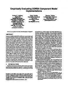
The data volume experiment is reported Figure 8. It presents the average case execution times collected during execution of a single case instances, composed of 20 sequential activities. The increase of the data volume does not influence much the performance of the system as the number of concurrent cases. The behavior of the centralized and distributed executions is very similar. It is clear that the growth rate (linear coefficient of the approximation lines) of the distributed cases is smaller than the one in the centralized configuration. In fact the growth rate for the distributed execution is less than half of that for the centralized distribution, if we assume that the growth is linear. Unfortunately given the small number of sample points, one cannot verify other hypothesis such as that the growth is not linear, but say quadratic. The data in Figure 7 also shows that there is no significant difference in the total execution time between cases running the experiments with two or four distributed hosts. The four host configuration has all coordinators in a single host, while the execution of the activities alternate between the remaining three. Thus, the example shows that the loss of performance due to the processing of the asynchronous event notifications, in the distributed case, is not significant. The placement of the case, process and role coordinators does not carry any significant impact to the overall system performance. As for the exchange of data, Figure 8 shows that there is no significant difference between transferring data within a single machine or between two machines. Neither CORBA nor WONDER makes any optimization regarding local transfer of data, since the CORBA framework does not distinguish between local and remote op-
9
eration invocation. Hence, independent of the location of the server object, the data exchange between client and server is performed using the IIOP over the TCP/IP stack. Averange Case Execution Time 700 Time (sec.)
600 500
y = 23,896x + 461,54 R2 = 0,9338
y = 27,356x + 440,11 R2 = 0,9305 Distributed Centralized
400 300
Linear (Distributed) Linear (Centralized)
200 100 0 961,5
2884,5
5769
8653,5
11538
14422,5
Amount of Data Exchanged Between Activities (KB)
Figure 8. Average case execution time. Increase of data exchanged among consecutive activities. Single case. As a solution to this problem, instead of transferring data through the TCP/IP stack, these information could be exchanged using shared memory, pipes or local files, for example. Another optimization that was not implemented is the execution of CORBA servers as threads in the same process. Going back to Figure 7, the average execution time associated with the centralized configuration of the tests overcame the distributed execution after the first instances. The use of CORBA objects, written in Java, executing in different virtual machines, do not provide a good performance in centralized environments, in which the number of concurrent cases is big. In distributed scenarios, however, where the number of servers executing in one node is smaller, its performance is acceptable. The biggest delay, associated to the mobility of the architecture agent, is the creation overhead of these objects. This procedure consumes memory and CPU. It also have influence in the performance of the other objects executing in the same host.
4.3. Summary The WONDER architecture was not designed to be executed in a centralized way. With more than 5 concurrent cases, the architecture presents a better performance if a distributed configuration is used. The growth of the execution time, given the number of concurrent cases, is less than half for the distributed configuration in comparison with the centralized one. Finally, the scalability of the system can always be improved by increasing the number of hosts in the system. It must be pointed out that running the WONDER in a centralized configuration cannot be compared with a optimized centralized WFMS implementation. Centralized workflow management systems have many optimizations embedded into the system that are not present in the
WONDER architecture. Thus the only possible conclusion from the scalability tests is that the WONDER architecture in a distributed configuration scales much better than WONDER in the centralized configuration. Possibly, the overhead data can be compared with centralized workflow management systems. In the worst case the WONDER architecture took 26 seconds from the end of an activity to the beginning of the next. Communication of distributed ones, using centralized tests could have a better distributed scenarios (maybe for instances with concurrent cases). However, for instances for bigger the distributed execution would overcome the equivalent as CPU system Even though the tests were performed using a simplified prototype implementation, its behavior would not be very different if the other components were fully implemented. The notification sent to the coordinators is asynchronous. The processing of these messages do not introduce delays in the agent migration procedure. Backup servers would only execute during low usage periods of the system. The only component that could introduce delays in the agent migration procedure is the Role Coordinator. More complex queries, requesting history information could increase the negotiation phase of the agent in some seconds. This query, however, is specific of some activities and is out of the scope of the present work.
5. Related Work Some of the components of the Exotica project [9], [10], [11], [12] developed at IBM Almaden Research Center, have similarities to our proposal. In particular the Exotica/FMQM (Flowmark on Message Queue Manager) architecture is a distributed model for WFMSs, using a proprietary standard (MQI - Message Queue Interface) of persistent queues. The case data is bundled in a message that is conveyed from one activity to the other through a fault tolerant persistent queue. Nevertheless, the proposal is not very detailed on how to deal with all the other requirements for a WFMS. The OMG Workflow Management Facility [5] implements workflow framework that satisfies the basic workflow management requirements. This specification is based on the WFMC standards and defines a set of basic objects and interfaces. Because of its generality, this specification was not designed to handle the large-scale workflow specific requirements. The Mentor Project [6] of the University of Saarland is a scalable, traceable workflow architecture. Fault tolerance is achieved by using TP-Monitors and logs. CORBA is used as a communication and integration support for heterogeneous commercial components. Scalability is achieved by replicating the data in backup servers. Simi-
10
lar to the WONDER architecture, the data and references to data are exchanged between Task List Managers when the activities are being executed and terminated. A limited first prototype was implemented and future extensions will include support for dynamic change of processes and the rollback of cancelled or incomplete workflows. Rusinkiewicz et. al, from Houston University, developed a workflow model based on INCAs (Information Carriers) [13]. This model was developed to support the execution of dynamic workflow processes. The process is executed over autonomous execution units (hosts). In this architecture, the process definition and the workflow data are wrapped in a container called INCA. The WONDER architecture extends the INCA concept with the mobile agent paradigm, defining active entities (the ActivityManagers) which interpret the case plan. INCAs are passive entities which execute in active hosts (service providers), while the WONDER model defines active entities that execute in passive hosts. Instead of defining compensation actions for fault tolerance, like the INCAs model, the WONDER allows the specification of compensation activities. The INCAs checkpointing police, which stores copies of the agent in the hosts of the system, is also similar to the one in the WONDER model. The auditing, monitoring and dynamic allocation of actors, however, is not addressed by the INCAs model.
6. Conclusions In this paper we presented the WONDER, a distributed architecture for large scale workflow enactment. The architecture is based in the idea that the case moves from user’s host to user’s host, following the process definition. The case is implemented as a mobile agent that implements weak migration (there is no code mobility). A set of coordinators and servers were defined in the basic architecture so that all other requirements of a WFMS could also be contemplated. Such decentralization of control and data allows for the definition, enactment and management of large-scale workflows, providing the necessary scalability for these applications. The WONDER uses the CORBA communication framework as its basic communication and distribution system. The CORBA hides all low-level communication and distribution issues, providing location and access transparencies in a standard object-oriented programming framework. The Java language facilitates the mobile object implementation, allowing the serialization/de-serialization of the case state and data, besides being portable among different hardware and operating system environments. Network delays are not significant in our application,
since most of the activity processing time will be spent in user interaction with the invoked applications. The use of CORBA 2.0 as the support environment for such architecture has problems with the persistence of objects. The standard CORBA 2.0 references were not designed for applications in which objects can be dynamically deactivated and reactivated, in different host ports, during its life cycle. In newer versions of CORBA, however, as the CORBA 3.0, this problem is solved by the POA object adapter. The information about where an activity should be created and executed is an important issue in our architecture. An application specific naming space was created using persistent location-dependent object names. Some CORBA services were not used due to simplifications and requirements of our architecture. A set of performance tests were performed. In these tests, the system had a linear increase of the execution times with the increase of the number of concurrent cases and the volume of data exchanged. The overhead associated to Java objects creation represent almost 40% of the total object migration time. Future extensions will include support for dynamic change of process definitions and ad-hoc workflows. This last feature can benefit from the fact that the WONDER distributed and autonomous approach facilitates the change of the plan during the case execution, since the workflow activities and user allocation is done on demand, at runtime, using the process definition enacted by the mobile object. Acknowledgments. The authors would like to thank FAPESP (Process 98/06648-0) , CNPq, CAPES, and the Pronex - SAI project - MCT/Finep for their support.
7. References [1] Jablonski, S. and Bussler, C. 1996. Workflow Management - Modeling Concepts, Architecture and Implementation. International Thomson Computer Press. [2] WFMC-TC-1011. 1996. Terminology Glossary. WFMC. [3] Silva Filho, R. S. and Wainer J. and Madeira E. R. M. and Ellis C. 2000. CORBA Based Architecture for Large Scale Workflow . Special Issue on Autonomous Decentralized Systems. IEICE Transactions on Communications. Tokyo, Japan, E83-B(5), pages 988-998. [4] 1995. The Common Object Request Broker: Architecture and Specification. OMG. [5] 1999. OMG Workflow Management Facility - Joint submission. OMG. [6] Weissenfels, J. and Wodtke, D. and Weikum, G. and Dittrich, A. 1997. The Mentor Architecture for Enterprisewide Workflow Management. Technical report. University of Saarland, Department of Computer Science.
11
[7] Weather, S. and Shrivastava, S. and Ranno, F. 1998. CORBA Compliant Transactional Workflow System for Internet Applications, from Proc. Middleware’98. Pages 317. [8] Stewart, R. and Rai, D. and Dalal, S. 1999. Building Large-Scale CORBA-Based Systems. Component Strategies, 59, pages 34-44. [9] Kamath, M. and Alonso, G. and Gunthor, R. and Mohan, C. 1996. Providing High Availability in Very Large Workflow Management Systems, from Proceedings of the Fifth International Conference on Extending Database Technology (EDBT’96). Avignon, France. Pages 2529. [10] Alonso, G. and Agrawal, D. and El Abbadi, A. and Mohan, C. and Gunthor, R. and Kamath M. 1995. A Persistent Message-Based Architecture for Distributed Workflow Management, from Proceedings of the IFIP WG8.1 Working Conference on Information Systems Development for Decentralized Organizations. Trondheim, Norway. [11] Mohan, C. and Alonso, G. and Gunthor, R. and Kamath, M. and Reinwald, B. 1995. An Overview of the Exotica Research Project on Workflow Management Systems, from Proc. 6th Int. Workshop on High Performance Transaction Systems. [12] Mohan, C. and Agrawal, D. and Alonso, G. and El Abbadi, A. and Guthor, R. and Kamath, M. 1995. Exotica: A project on Advanced Transaction Management and Workflow Systems, from ACM SIGOIS Bulletin. 16(1). [13] Barbara, D. and Mehrotra, S. and Rusinkiewicz, M. 1996. INCAs: Managing Dynamic Workflows in Distributed Environments. Journal of Database Management, 7(1).
12