WORKFLOW PARTITIONING IN MOBILE INFORMATION SYSTEMS Luciano Baresi1 , Andrea Maurino1 , and Stefano Modafferi1 1 Politecnico di Milano
Dipartimento di Elettronica e Informazione P.zza L. Da Vinci 32 - 20133 - Milano Italy baresi, maurino,
[email protected]
Abstract The increasing success of wireless technologies is sustaining the diffusion of mobile information systems, but the youth of the underlying technology and its peculiar characteristics are impacting the development of such systems. For example, the execution of business processes in such a context must cope with the variable and fluctuating bandwidth available to the different devices. This leads the designer to stress the independence of each actor – by minimizing interactions and knowledge sharing – to increase the reliability of the whole system. To this end, the paper proposes a rigorous approach for partitioning the execution of BPEL4WS workflows on sets of portable devices, that is, the infrastructure of mobile information systems. The approach abstracts BPEL4WS processes into attributed graphs and uses a graph transformation system as rules to split single workflows into meaningful sets of related processes. The paper presents such rules and exemplifies them on a case study in the cultural heritage domain. Keywords: Mobile information systems, distributed workflows, partitioning rules
1.
Introduction
In these years, mobile technologies are deeply changing our way of leaving. The more these technologies become reliable and widely available, the more business scenarios use them. New wireless technologies, like Bluetooth or Wi-Fi, are creating the technological backbone for mobile information systems (MobIS): The structure of these systems is not fixed and all business processes must be able to deal with nomadic actors and dynamic changes. It is true however that the youth and limitations of these technologies still impact the systems that run on them: Roam-
2 ing, frequent disconnections, and security holes [Gaertner and Cahill, 2004; Vaughan-Nichols, 2003], along with the variable bandwidth offered by the wireless medium, must be taken into account to design and implement reliable mobile systems. The execution of a business process in a mobile environment – with different devices connected through different network technologies – needs new strategies with respect to the traditional solutions adopted for centralized workflows. These solutions rely on a single engine that knows and controls all system resources, but mobility demands for decentralized executions carried out by a federation of heterogenous devices. All these requirements lead to a new strategy that stresses the independency among actors – to minimize the necessity of interaction and knowledge sharing – and thus increases reliability. This paper tackles the problem by proposing formal partitioning rules to transform a unique workflow into a set of federated workflows that can be executed by different engines. This is the typical scenario where different devices contribute to the enactment of the whole process by executing a fragment and synchronizing with the others. The paper builds upon the approach described in [Maurino and Modafferi, 2004] for transforming BPEL processes and paves the ground to the release of an automatic slicing engine for the run-time partitioning of business processes. Partitioning rules exploit the UML profile for BPEL [Thatte, 2003], to abstract workflows as attributed graphs (i.e., stereotyped activity diagrams), and graph transformation theory [Baresi and Heckel, 2002] to formally specify the steps that lead to the separate workflows (i.e., the set of graphs). The rules are implemented by using AGG (Attributed Graph Grammars, [Beyer, 1992]) as supporting tool for both modeling and validation. Two other results of the paper are the validation of the proposed rules and its application to a case study in the cultural heritage domain. The paper is organized as follows. Section 2 introduces graph transformation to set the basis of this work. Section 3 describes the partitioning rules identified for moving from centralized to decentralized workflow executions. Section 4 applies the rules on an example process taken from the risk management in the cultural heritage domain. Section 5 summarizes the related work on decentralized workflow models and Section 6 concludes the paper.
3
Workflow Partitioning in Mobile Information Systems
2.
Graph transformation
Before describing our partitioning rules, we introduce graph transformation [Baresi and Heckel, 2002] as the formal background needed to understand them. A typed graph transformation system G = hT G, C, Ri consists of a type graph T G, a set of structural constraints C over T G, and a set R of rules p : L → R over T G. The type graph defines the types of nodes and edges that can be used to create graphs. The set of structural constraints identifies constraints on how nodes and edges are linked, and rules state how graphs can be modified. In particular, a graph transformation rule r : L → R consists of a pair of T G-typed instance graphs L, R such that the intersection L ∩ R is well-defined (this means that, e.g., edges which appear in both L and R are connected to the same vertices in both graphs, or that vertices with the same name have the same types, etc.). In other words, the left-hand side L defines the pre-conditions that must hold on the graph to enable the rule while the right-hand side R describes the post-conditions, that is, the modifications on the graph after applying the rule. The application of a graph transformation rule comprises three steps: We find an occurrence oL of the left-hand side L in the current graph G (the BPEL process, in our case). We remove all the vertices and edges from G which are matched by L \ R. The remaining structure D := G \ oL (L \ R) must be a legal graph: no edges are left dangling because of the deletion of their source or target vertices. In this case, the dangling condition is violated and the application of the rule is prohibited. We glue D with a copy of R \ L to obtain the derived graph H. We assume that all newly created objects, links, and attributes get fresh identities, so that G ∩ H is well-defined and equal to the intermediate graph D. Usually, rules must be composed to peform significant transformap1 (o1 )
pn (on )
tions. Thus, a transformation sequence s = (G0 =⇒ · · · =⇒ Gn ) in s ∗ G, briefly G0 =⇒G Gn , is a sequence of consecutive transformations using the rules of G such that all graphs G0 , . . . , Gn satisfy the topological constraints. In this paper, we concentrate on AGG (Attributed Graph Grammars, [Beyer, 1992]) to model and validate our rules. AGG allows users to specify complex structures as graphs and exploits the Java type system to associate attributes with values. It also supports layered rules where
4 layers fix the application order among rules. The interpretation starts with level-zero rules and then moves to higher ones. Besides pre- and post-conditions (left- and right-hand side graphs), AGG also supports negative application conditions, that is, sub-graphs in the left-hand side that must not exist to enable the rule. Additionally, rules can embed conditions on attribute values in the form of boolean Java expressions.
3.
Partitioning rules
The Business Process Execution Language for Web Services [Thatte, 2003], hereafter BPEL, provides an XML notation for specifying the behavior of businesses based on Web Services. A BPEL process is defined in terms of its interactions with the partners that provide services, require services, or participate in a two-way interaction with the process. In this paper, we do not present the XML representation of these processes, but we adopt an extended version of the UML profile for automated business processes, described in [Gardner and al., 2003], to render the workflows as stereotyped UML activity diagrams and thus attributed graphs as summarized in Table 1. BPEL Primitive Basic Activities
Links between activities Structured activities
Table 1.
Graph Element Basic activities are rendered as Activity nodes. Each of these nodes has an attribute device, which stores the name of the device that controls the activity, a type, equal to normal, and a name equal to the one of the UML activity. Links are rendered as edges of type follow between Activity nodes. Structured activities are rendered with two special-purpose Activity nodes. Their attributes type and name have the same values and are equal to Start and End, where is the type of the corresponding UML structured activity (e.g., Loop or Switch). Each structured activity is also associated with a number, which is assigned to the variable value of the two added Activity nodes.
Translation guidelines
Partitioning rules operate on such an abstract representation to create the set of cooperating workflows. The application of partitioning rules – and the execution of disconnected operations – requires that the workflow meets the following requirements: (1) The control of the execution of a specific task can be assigned to a single device; (2) The StartLoop
Workflow Partitioning in Mobile Information Systems
5
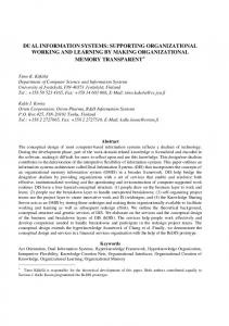
and EndLoop nodes of While structured activities must be assigned to the same device; (3) The Start node of Pick, Switch, and While structured activities is in charge of evaluating the condition; (4) The workflow has no global variables and all the variables are passed as parameters between different actors. If all requirements are met, the partitioning process starts identifying where to partition the workflow and how to maintain the execution flow across structured activities. Then it defines the sub-workflows by creating local views. Rules are organized in layers that govern their applicability. Rules that belong to “low” layers are applied before those of “high” layers. Within each layer, rules can triggered in a non deterministic way. The lowest-level rules (layer 0) are devoted to synchronizing (delegating) the execution flow between two activities of a Sequence that are executed by different devices. Fig. 1(a) shows the AGG rule Add delegate that synchronizes Sequences split on different devices. The rule can be applied if there is an Activity node (either simple or structured), controlled by an actor A1 followed by another Activity node controlled by a different actor A2 . The right-hand side of the rule introduces two new special Activity nodes where the former is controlled by A1 , and the latter by A2 . These two nodes add a pair of invoke/receive activities to forbid the second activity to start before the completion of the first one. Notice that this rule is also able to partition Sequences that belong to Flow activities. The delegation (synchronization) is described by the delegate arc between the two newly introduced Activity nodes. The main problem with partitioning structured activities, like Switch or Pick ones, is to be sure that all devices involved in such activities follow the same branch. In fact, while in Flow activities all branches are executed in parallel, in Switch activities only one branch is executed. Consequently, rules of layer 1 identify all the controllers involved in such structured activities and add a Flow activity before any Switch (resp Pick) node to communicate the chosen branch to the other controllers. Fig. 1(b) shows the rule IdentifyStartSwitch (layer 1) that identifies Switch nodes. The right-hand side of the rule identifies the beginning of a Switch activity. Notice that the existence of the rule Add Delegate ensures that there always exists an Activity node controlled by the same device as the one controlled by the StartSwitch node. Rule AddStartSwitch (layer 1), not shown here, marks all activities directly connected to StartSwitch nodes with isSwitched arcs. Each arc is enriched with two attributes: device and value. The former represents the device that controls the switch; the latter identifies the specific switch controlled by the device.
6
1:Activity device=A1
follow
AddDelegate
2:Activity device=A2 name=N
:= follow 1:Activity device=A1
Activity device=A1 type=”Normal” name=”Do “ +N+” To “+ A2 value=0
delegate
Activity device=A2 type=”Normal” name=”Execute “ +N+ “from “+A1 value=0
2:Activity device=A2 name=N
1:Activity device=X value=V1
follow
:= follow 1:Activity device=X
Activity device=X type=”StartFlow” name=”StartFlow” value=H
3:isSwitched device=X value=H
(a)
2:Activity device=X type=”StartSwitch” name=”StartSwitch” value=V
Activity follow device=X type=”EndFlow” name=”EndFlow” value=H
IdentifyStartSwitch
beforeSwitch 2:Activity device=X type=”StartSwitch” name=”StartSwitch” value=H
isSwitched device=X value=H follow 1:Activity 2:Activity
3:isSwitched device=X value=H follow
1:Activity
2:Activity
:=
3:isSwitched device=X value=H 4:Activity
:=
(b)
IterateSwitch
(c)
1:Activity device=X type=”StartFlow” name=”StartFlow” value=H
1:Activity device=X type=”StartFlow” name=”StartFlow” value=H follow 2:Activity device=X type=”EndFlow” name=”EndFlow” value=H isSwitched device=X value=H
follow
follow 2:Activity device=X type=”EndFlow” name=”EndFlow” value=H
Activity device=X type=”Normal” follow name=”SendDec” value=H follow Activity follow device=X type=”Normal” name=”ReceiveDec” value=H
IterateRemoveSwitch
Remove SwitchArc
4:Activity
(d)
RemoveOtherDevice 1:Activity
:=
follow
1:Activity 1:Activity (e)
Figure 1.
4:Controller device=X
2:Activity follow device=X1 3:Activity type=”Normal”
Partitioning rules
1:Activity
:=
4:Controller device=X follow
3:Activity
(f)
Workflow Partitioning in Mobile Information Systems
7
Starting form these isSwitched nodes, four further rules (layer 2) mark all activity nodes involved in the Switch activity. Fig. 1(c) shows one of such rules. This rule is applied when a node with an isSwitched arc follows another node without such arc. The right-hand side adds a new isSwitched arc to the latter node. Similarly, the rules that belong to layers 1 and 2 deal with Pick structured activities. These rules are very similar to the ones described for Switch activities and are not shown here for lack of space. The partitioning of While activities is slightly more complex. The number of iterations is not known a-priori and the variables that control the loop can be updated by any actor involved in the activities that belong to the loop. Consequently, like for other structured activities, we introduce a Flow activity before the StartLoop node, with the goal of communicating to the other devices involved in the While activity if the condition is satisfied. We also add another Flow activity before the EndLoop node to communicate to the other devices if the loop condition is still satisfied. After suitably decorating Switch, Pick and While activities, the rules at layer 3 address the problem of partitioning them. These rules add special-purpose activities to notify the branch followed by the execution of a given structured activity. Rule Remove Switch Arc, shown in Fig. 1(d), describes it. The rule is activated when there exists at least one activity marked with an isSwitched arc whose attributes device and level are equal to those of the StartSwitch node. If the left-hand side is matched, the right-hand side adds two new Activity nodes between the Flow nodes created by the rules at layer 1 to communicate the followed branch. The last set of rules (layer 4) removes extra arcs added in layer 1. Fig. 1(e) shows the rule for removing isSwitched arcs. After extending the host graph (BPEL process), we can create the local views to decentralize the workflow execution. By “local”, we mean that each actor only knows its tasks, i.e., its sub-workflow. More details about local views in business processes can be found in [Van der Aalst and Weske, 2001]. To create views, we set the context in terms of the actor (device) for which we want to produce the view and apply the following rules: (1) We remove all activities whose execution is not controlled by the current actor; (2) We translate all structured activities, with the exception of Sequences, that do not include “local” activities into Sequences with no tasks. For example, Fig. 1(f) shows the rule RemoveOtherDevice that implements the first rule. The left-hand side is applied as long as we find a node not controlled by the specific device. The right-hand side removes that node and adds a direct arc to fill the hole, that is, between the two
8 tasks before and after the removed one. Notice that even if the whole workflow is composed of one task only, it is always connected to the nodes that correspond to the start and end of the workflow. The rule that corresponds to the second bullet is not presented here.
Validation. The feasibility of the described transformation depends on the assumptions that: Partitioning rules define a graph transformation system that exposes a functional behavior, i.e., is confluent and terminates; The execution flow of the original workflow is preserved. This means that the local process views do not alter the global execution. The first assumption is mandatory to ensure that the actual transformation does not depend on the order with which we apply rules (confluence) and does not enter infinite loops (termination). In other words, even if we apply the same set of rules in a different order, we obtain the same result. The second assumption is needed to preserve the original “behavior” even if we move from centralized to decentralized execution. We can check the first hypothesis by exploiting the critical pair analysis capabilities supplied by AGG. The set of critical pairs represents precisely all potential conflicts: given two rules p1 and p2, there exists a critical pair if and only if p1 may disable p2, or p2 may disable p1. If no conflicts exist between any pair of rules the graph transformation system has a functional behavior [Hausmann et al., 2002]. After designing our rules, we used AGG to check all possible pairs in the same layers, that is, all pairs of rules that could potentially be in conflict: After some modifications all layers do not present conflicts. As to the second hypothesis, currently we do not have a formal way to prove that partitioning does not alter the execution flow. We are conducting experiments with formal models that allow us to analyze the execution traces in the two cases (i.e., centralized and decentralized execution), but currently our proof is based on the observation that partitioning rules only add activities to synchronize the different subworkflows, which do not alter the execution flow. Even the rules that create the local views do not modify the execution flow because they create a view of the process by deleting those elements that are controlled by other devices and filling the holes with empty sequences. Besides these two observations, our confidence is supported by the results obtained on several case studies. One of them is presented in the next section.
Workflow Partitioning in Mobile Information Systems
4.
9
Example application
This section demonstrates the application of our rules on a significant case study in the cultural heritage. Interested readers can refer to [Maurino and Modafferi, 2003] for more details on the example. Italy probably hosts one of the widest and most significant cultural heritages in the world; unfortunately, because of many factors, they are in danger of destruction. This situation imposes the definition of an administrative and scientific instrument to manage and protect the huge cultural heritage. In 1990, the Italian government began a project to realize MARIS: the risk map of cultural heritage. In this case study, we consider that the MARIS system can be improved by using cooperative mobile information systems in the data acquisition phase. The goal of this map is to create a complete repository of the state of all cultural heritages in a given region. In particular the risk map aims at allowing users to process data regarding territorial danger factors and vulnerability conditions of monuments and helping local and state administrations improve their decision-making processes for conservative interventions. Since we concentrate on the data acquisition phase, we consider that we have to define a risk level associated with each site and create a site description card to fully describe it. All data must be stored electronically and consequently the data acquisition is facilitated by the use of mobile devices like laptops, PDAs, or smart phones. The whole process for managing the cultural risk map is composed of several sub/processes, some of them executed in parallel. The one presented here defines how to describe a given cultural site through a site description card (hereafter, card). The card is composed of a number of items and changes according to the specificities of what is described (e.g., a church, an archeological site, or an historical building). Fig. 2 shows a simplified process for filling in a card for a romanic church, where we foresee the use of four devices. The first step for partitioning the workflow of Fig. 2 is its translation into an AGG Graph. This is only a problem of using the right format: For example, the activity diagram can be saved as an XML/XMI file and then converted into a GXL file. XMI (XML Metadata Interchange) is the OMG standard XML format to exchange UML models. GXL is the XML-based language used by AGG to describe graphs. Then AGG applies iteratively the rules described in Section 3 to decorate the workflow and then create the sub-workflows. For example, we can apply rule Add Delegate to the Start Controller of the Flow activ-
10
Device 2
StaticRiskAnalysis
Device 3
Risks do not exist
Risk Description
Risks exist
DangerPhoto
Device 4
GPS Position
FrescoDescription
FrescoPhoto
Device 1
ReceiveFillIn
Damages exist
FrescoDamage Damages do not exist
returnReport
I = Invoke, RC = Receive, and RE = Reply
Device 1
Device 2
ReceiveFillIn receives the card that the team has to update. The completion of this task activates the Flow activity. FrescoDamage evaluates – and if needed describes – the damages on the frescos of the church. ReturnCard returns the filled card after terminating all branches of the Flow activity. Device 3
FrescoDescription supplies a textual description of damages on frescos. RiskDescription describes the risks from a given static problem in the site.
Device 4
DangerPhoto takes a picture of the static risk. FrescoDamagePhoto takes a picture of the damage on frescos.
Figure 2.
Static Risk Analysis evaluates the number of external damages in the analyzed site.
GPSPosition determines the exact GPS position of the static risk.
The process with its portions assigned to the devices
11
Workflow Partitioning in Mobile Information Systems
ity and the Static Risk Analysis activity to introduce two new tasks as shown in Fig. 3. Activity
Activity
Activity
Activity
Device=1 Type=”StartFlow” Name=”StartFlow” Value=1
Device=1 Type=”Normal” Name=”Do StaticRiskAnalysis To 2" Value=0
Device=2 Type=”Normal” Name=”Execute StatiRiskAnalysis From 1" Value=0
Device=2 Type=”Normal” Name=”StaticRiskAnalysis” Value=0
follow
Figure 3.
delegate
follow
Example of ADDDelegate rule
The last step is the definition, for each device, of the local view of the workflow, which for the sake of brevity are super-imposed onto the workflow directly in Fig. 2.
5.
Related work
The opportunities given by workflow distribution have been thoroughly studied in the field of business process design in the last ten years. The main goal of this research is the cooperation/integration among different companies, that is, among different workflows. This problem reappears nowadays with mobile information systems and the problems that come with them. In [Jablonski et al., 2001], the authors present a comparison among the different approaches to distribution. Cross-Flow [Grefen et al., 2000] provides high-level support to workflows in dynamically-created virtual organizations. Virtual organizations are created dynamically by contract-based match-making between service providers and consumers. In Agent Enhanced Workflow [Judge et al., 1998], the agent-oriented solution presents the interesting aspect of building execution plans using a goal approach. Event-based Workflow Process Management [Eder and Panagos, 1999] includes an event-based workflow infrastructure and addresses time-related aspects of process management. The main feature of ADEPT [Reichert and Dadam, 1998] is the possibility of modifying workflow instances at run-time. MENTOR [Muth et al., 1998] provides an autonomous workflow engine. In this approach the workflow management system is based on a client-server architecture. The workflow itself is orchestrated by appropriately configured servers, while the applications invoking workflow activities are executed on the client sites. In enterprise-wide applications, workflows may span multiple autonomous organizational units. Consequently, heterogeneity and scalability impose an approach in which a large workflow can be partitioned into a number of sub-workflows (e.g., based on organizational responsibilities) handled by different servers. It considers the workflow as a statechart that reflects the control flow among activities and uses orthogonal rules to partition it.
12 The METEOR (Managing End to End OpeRations [Anyanwu et al., 2003]) system leverages Java, CORBA, and Web technologies to support the development of enterprise applications that require workflow management and application integration. It enables the development of complex workflow applications that involve legacy information systems, are geographically distributed, and span multiple organizations. It also provides support for dynamic workflow processes, error and exception handling, recovery, and QoS management. Exotica [Mohan et al., 1995] is characterized by the possibility of disconnected operations. It does not permit complete decentralization because it maintains a central unit and all operations obey a client/server paradigm. WISE [Alonso et al., 1999] exploits the Web for its engine and offers an embedded fault handler. WAWM [Riempp, 1998] focuses on the problems related to workflow management in wide area networks. Mobile [Jablonski and Bussler, 1996] is developed to support inter-organizational workflows and is strongly based on modularity. This characteristic alleviates change management and also allows users to customize and extend aspects individually. The analysis of these proposals suggests two different and dual approaches to the problem of workflow coordination. The first approach supports the integration of autonomous and preexisting workflows and it aims mainly at the coordination of different and independent actors. The second approach supports the decomposition of single workflows to support its autonomous execution by means of different engines. CrossFlow, Agent Enhanced Workflow, Event-based Workflow process Management, Adept, WISE and WAWM belong to the first approach. Mentor, Exotica and Mobile belong to the second class. Described systems also offer three different solutions to the definition of partitioning and allocation rules. The first solution proposes specific definition languages (Cross-Flow, Agent enhanced workflow, Mentor, Exotica). The second solution proposes the extension of workflow languages with distribution rules (Cross-Flow, ADEPT, WISE, WAWM, Mobile). The third solution does not consider the language for distribution rules (Event-based, workflow Process Management). Cross-Flow belongs to more than one class because the distribution rules are split into several parts. Our delegation model supports disconnected components, like Exotica, the independence of workflow engines, like MENTOR, and the possibility of modifying the workflow instance at run-time, like ADEPT. Moreover, we argue that the mobile environment needs a language strongly oriented to the automatic execution, like BPEL, but we also demand for lightness, which is a mandatory feature if the system runs on
Workflow Partitioning in Mobile Information Systems
13
portable devices in ad-hoc networks. As far as the definition of rules is concerned, our approach defines partitioning rules, but does not define allocation rules. It demands them to the specific business process and application domain.
6.
Conclusions and future work
The paper presents an approach for partitioning the execution of BPEL processes onto a network of mobile devices. The approach produces an overall execution model that is “equivalent” to the centralized one, but supports disconnected components and independent workflow engines. Partitioning rules are specified using a graph transformation system and implemented using a special-purpose tool called AGG. In this paper, we demonstrate that these rules do not alter the execution flow by means of sound observations and the presentation of a case study. The complete demonstration is part of our future work. We are also working on making presented rules more robust and on analyzing the transactional behavior of partitioned sub-workflows. The final goal is the definition of an automatic engine for the runtime partitioning of workflows to execute them on a federation of mobile devices.
Acknowledgments.. This work has been developed within the Italian MURST-FIRB Project MAIS (Multi-channel Adaptive Information Systems) [MAIS Consortium, mais]. We are grateful to Prof. B. Pernici for the profitable discussions about the arguments of this paper.
References Alonso, G., Fiedler, U., Hagen, C., Lazcano, A., Schuldt, H., and Weiler, N. (1999). WISE: Business to business e-commerce. In RIDE, pages 132–139. Anyanwu, K., Sheth, A., Cardoso, J., Miller, J., and Kochut, K. (2003). Healthcare enterprise process development and integration. Journal of Research and Practice in Information Technology, 35(2). Baresi, L. and Heckel, R. (2002). Tutorial Introduction to Graph Transformation: A Software Engineering Perspective. In Proceedings of the First International Conference on Graph Transformation (ICGT 2002), volume 2505 of Lecture Notes in Computer Science, pages 402–429. Springer-Verlag. Beyer, M. (1992). AGG1.0 - Tutorial. Technical University of Berlin, Department of Computer Science. Eder, J. and Panagos, E. (1999). Towards distributed workflow process management. In In proc. of Workshop on cross-Organizational Workflow Management and Coordination, San Francisco, USA.
14 Gaertner, G. and Cahill, V. (2004). Understanding link quality in 802.11 mobile ad hoc networks. Internet Computing, 8:1:55 – 60. Gardner, T. and al. (2003). Draft uml 1.4 profile for automated business processes with a mapping to the bpel 1.0. IBM alphaWorks. Grefen, P., Aberer, K., Hoffner, Y., and Ludwig, H. (2000). Crossflow: Cross-organizational workflow management in dynamic virtual enterprises. International Journal of Computer Systems Science & Engineering, 15(5):277–290. Hausmann, J. Hendrik, Heckel, R., and Taentzer, G. (2002). Detection of conflicting functional requirements in a use case-driven approach: a static analysis technique based on graph transformation. In International Conference on Software Engineering, pages 105–115. Jablonski, S. and Bussler, C. (1996). Workflow Management: Modeling Concepts, Architecture and Implementation. International Thomson. Jablonski, S., Schamburger, R., Hahn, C., Horn, S., Lay, R., Neeb, J., and Schlundt, M. (2001). A comprehensive investigation of distribution in the context of workflow management. In In proc. of International Conference on Parallel and Distributed Systems ICPADS, Kyongju City, Korea. Judge, D., Odgers, B., Shepherdson, J., and Cui, Z. (1998). Agent enhanced workflow. BT Technical Journal, (16). MAIS Consortium (http://black.elet.polimi.it/mais/). Mais: Multichannel Adaptive Information Systems. Maurino, A. and Modafferi, S. (2003). Challenges in the designing of cooperative mobile information systems for the risk map of italian cultural heritage. 1st Workshop on Multichannel and Mobile Information Systems, held in conjunction of conference on Web information Systems Engineering, 2003, Roma. Maurino, A. and Modafferi, S. (2004). Workflow management in mobile environments. In proc. of International Workshop on Ubiquitous Mobile Information and Collaboration Systems UMICS, Riga, Latvia. Mohan, C., Alonso, G., Gunthor, R., and Kamath, M. (1995). Exotica: A research perspective of workflow management systems. Data Engineering Bulletin, 18(1):19–26. Muth, P., Wodtke, D., Weisenfels, J., Dittrich, A. Kotz, and Weikum, G. (1998). From centralized workflow specification to distributed workflow execution. Journal of Intelligent Information Systems, 10(2):159–184. Reichert, M. and Dadam, P. (1998). Adeptflex − supporting dynamic changes of workflows without losing control. Journal of Intelligent Information Systems, 10(2):93– 129. Riempp, G. (1998). Wide Area Workflow Management. Springer, London, UK. Thatte, S. (2003). Business process execution language for web services. www-106. ibm.com/developerworks/webservices/library/ws-bpel/. Van der Aalst, W.M.P. and Weske, M. (2001). The p2p approach to interorganizational workflows. In In Proc. of Conference on Advanced Information Systems Engineering CAiSE, pages 140–156, Interlaken, Switzerland. Vaughan-Nichols, S.J. (2003). The challenge of wi-fi roaming computer. IEEE Computer, 36:7:17–19.