KI-NA-25874-EN-N
EU
The objective of the project was to develop a new modelling-based optimisation and quality control system for continuous casting. The concept was based on studying critical parameters affecting steel quality and finding safety ranges for them to ensure good quality in continuous casting.
Integrated models Integrated models for defect free casting (Deffree)
Several fundamental and semi-empirical models were developed in the project. The critical features affecting steel quality were defined through mathematical modelling and industrial casting trials. Both good quality casts and casts with some defects were simulated to find features which have an effect on steel quality. Cracking indices, fluid flow parameters in the mould and segregation severity parameters are examples of critical parameters defined in the project. Safety ranges inside which the critical parameters had to stay during casting were determined in steady-state casting conditions. If a critical feature could not be adjusted on-line during casting, for example, surface velocity of liquid in the mould, this feature was expressed as a function of casting parameter, e.g. casting speed, which can be controlled and modified during casting. For optimising and controlling steel quality during casting the following online models were developed in the project: transient 2D centreline segregation model, dynamic 3D heat transfer model and inverse mould heat flux difference model. These models can be applied also to other casters for online simulation, once the caster has been set up and casting process data is available.
Studies and reports
EUR 25874
doi:10.2777/57608
for defect free casting (Deffree)
Research and Innovation
EUR 25874 EN
HOW TO OBTAIN EU PUBLICATIONS Free publications: • via EU Bookshop (http://bookshop.europa.eu); • at the European Union’s representations or delegations. You can obtain their contact details on the Internet (http://ec.europa.eu) or by sending a fax to +352 2929-42758. Priced publications: • via EU Bookshop (http://bookshop.europa.eu). Priced subscriptions (e.g. annual series of the Official Journal of the European Union and reports of cases before the Court of Justice of the European Union): • via one of the sales agents of the Publications Office of the European Union (http://publications.europa.eu/others/agents/index_en.htm).
EUROPEAN COMMISSION Directorate-General for Research and Innovation Directorate G — Industrial Technologies Unit G.5 — Research Fund for Coal and Steel E-mail:
[email protected] [email protected] Contact: RFCS Publications European Commission B-1049 Brussels
European Commission
Research Fund for Coal and Steel Integrated models for defect free casting (Deffree) S. Louhenkilpi, H. Kytönen Aalto University (AALTO) School of Chemical Technology, PO Box 11000 (Otakaari 1), 00076 AALTO, Espoo, FINLAND
M. De Santis, S. Fraschetti, A. Gotti, M. R. Ridolfi, P. Vescovo Centro Sviluppo Materiali S.p.A (CSM) Via di Castel Romano 100, 00128 Rome, ITALY
R. Koitzsch VDEh-Betriebsforschungsinstitut GmbH (BFI) PO Box 105145, Sohnstraße 65, 40237 Düsseldorf, GERMANY
E. Balducci, C. Andrianopoli Cogne Acciai Speciali S.P.A.Socio Unico (CAS) Via Paravera 16, 11100 Aosta, ITALY
G. Martin, A. Mollo Duferco Belgium S.A. (DUFERCO) Rue Anna Boch 34, 7100 La Louvière, BELGIUM
Z. Csepeli, R. Josza, M. Réger ISD Dunaferr Dunai Vasmű Zártkörűen Működő Részvénytársaság Zrt. (DUNAFERR) PO Box 110, Vasműtér 1-3, 2400 Dunaújváros, HUNGARY
Grant Agreement RFSR-CT-2008-00007 1 July 2008 to 31 December 2011
Final report
Directorate-General for Research and Innovation
2013
EUR 25874 EN
LEGAL NOTICE Neither the European Commission nor any person acting on behalf of the Commission is responsible for the use which might be made of the following information. The views expressed in this publication are the sole responsibility of the authors and do not necessarily reflect the views of the European Commission.
Europe Direct is a service to help you find answers to your questions about the European Union Freephone number (*):
00 800 6 7 8 9 10 11 (*) Certain mobile telephone operators do not allow access to 00 800 numbers or these calls may be billed.
More information on the European Union is available on the Internet (http://europa.eu). Cataloguing data can be found at the end of this publication. Luxembourg: Publications Office of the European Union, 2013 ISBN 978-92-79-29038-1 doi:10.2777/57608 © European Union, 2013 Reproduction is authorised provided the source is acknowledged. Printed in Luxembourg Printed on white chlorine-free paper
TABLE OF CONTENT 1 FINAL SUMMARY ..................................................................................................................................... 5 1.1 Objectives of the project ............................................................................................................................ 5 1.2. Work done and results .............................................................................................................................. 5 1.2.1 WP1 Definition of reference casting conditions .................................................................. 5 1.2.2 WP2 Simulation of mould powder behaviour ..................................................................... 6 1.2.3 WP3 Simulation of fluid flow and solidification behaviour ................................................ 7 1.2.4 WP4 Simulation of phase transformation ............................................................................ 9 1.2.5 WP5 Model application and validation in steady-state condition ....................................... 9 1.2.6 WP6 Development and application of the empiric on-line model optimised for process control .................................................................................................................................. 12 2 SCIENTIFIC AND TECHNICAL DESCRIPTION OF RESULTS..................................... ............ .....15 2.1 Objectives of the project.......................................................................................................... ......... .....15 2.2 Comparison of initially planned activities and work accomplished. ...................................................... 16 2.3 Description of activities and discussion............................................................................................. ....16 2.3.1 WP1 Definition of reference casting conditions ................................................................ 16 2.3.2 WP2 Simulation of mould powder behaviour.................................................................... 22 2.3.3 WP3 Simulation of fluid flow and solidification behaviour .............................................. 35 2.3.4 WP4 Simulation of phase transformation .......................................................................... 49 2.3.5 WP5 Model application and validation in steady-state condition ..................................... 53 2.3.6 WP6 Development and application of the empiric on-line model optimised for process .........................................................................................................111 2.4 Conclusions ............................................................................................................................................ 123 2.5 Exploitation and impact of the research results .................................................................................... 125 3 List of Figures and Tables......................................................................................................................... 126 4 List of References ..................................................................................................................................... 130 List of Symbols ............................................................................................................................................ 132 Appendix 1 – Appendix Figures and Tables ............................................................................................... 133 Appendix 2 – Deliverables........................................................................................................................... 139 Appendix 3 - Critical parameters and safety ranges .................................................................................. 141 Appendix 4 - General description of the Liquid Motion Intensity (LMI) model by OBUDA and DUNAFERR ................................................................................................................................................ 146
3
1 FINAL SUMMARY Introduction DEFFREE project was a collaboration b etween Aalto University, CSM, BFI, C ogne Acciai Speciali, Duferco Belgium and ISD Dunaferr, as wel l as i ts s ubcontractors Ob uda U niversity an d C ollege o f Dunaujvaros. The project was coordinated by Aalto. The o utcome o f each t ask i s s ummarised b elow i n chapter “1 Final summary”. M ore d etailed descriptions o f wo rk d one an d t he r esults ar e i n ch apter 2 “Scientific and te chnical d escription of results”. Deliverables and reported in Appendix 2. “Conclusions of the project” and “Exploitation and impact of research results are given in the end of the report.
1.1 Objectives of the project The m ain o bjective o f t he p roject was t o de velop a ne w m odelling ba sed o ptimisation a nd quality control s ystem f or c ontinuous c asting. T he ne w c oncept is based o n critical parameters a ffecting t he steel quality and finding safety ranges for the parameters in order to ensure good quality in continuous casting. T hese c ritical p arameters were o btained f rom casting e xperiments an d f rom mathematical models.
1.2 Work done and results 1.2.1 WP1 DEFINITION OF REFERENCE CASTING CONDITIONS Objective of this WP was to specify casters and steel grades which will be studied in this project as well as to provide cas ter an d cas ting p rocess d ata f or t he partners for mod elling w ork. T he kn owledge of interrelations be tween c asting pa rameters a nd pr oduct qua lity i ncluding pr ocess s tability ha s be en summarised.
Task 1.1 Specification of the casters of the industrial partners being investigated (all partners) In t his ta sk, c asters o f th e in dustrial partners were specified. Industrial p artners in t his project w ere DUFERCO, CAS and DUNAFERR. DUFERCO and CAS have b illet cas ters an d DUNAFERR vertical s lab cas ter. DUFERCO and DUNAFERR produce car bon s teels, CAS stainless steels. Steel grades wh ich were investigated in this project were determined and databases of caster machine d ata, operational p arameters an d cas ting p rocess p arameters wer e d elivered f or t he p artners f or m odel development. The investigated steel grades were: • • •
DUNAFERR: DD13, DD14, S235JRG2, S355J2G3C and St 52-3 CAS: F304L1, 420A7 DUFERCO: cold-headed s teel g rades ( mainly 20MnB4 a nd 3 0MnB4), pe ritectic C Mn-Ti steel C10C and high carbon grade C72D2
Industrial pa rtners de livered a ll t he d ata required f or modelling a nd o ther in vestigations; chemical compositions, material data, caster geometries and process parameters.
5
Task 1.2 Summarising known interrelation between casting parameters and product quality as well as process stability (all partners) In general, al l t he p artners were f ocusing o n d etermining i nterrelations b etween cas ting p arameters, product qua lity a nd pr ocess s tability b ased o n c ommon k nowledge, results f rom f ormer p rojects, literature and discussions between the partners. As a result from the investigations BFI selected three critical variables which can be investigated with the BFI tools th at were the c ritical v elocity a t th e s teel m elt/liquid f lux in terface, th e liq uid f lux thickness and the wave height at the meniscus. CAS and CSM identified the main p hysical an d geometrical p arameters a ffecting the p roduct q uality which are related t o the t ypes of d efects found. Both thermocouple d ata from CAS and solidification and shell stress modelling by CSM have been targeted at finding the conditions leading to undesirable shell growth. DUFERCO collected a table of influencing factors for the main surface defects on castings. AALTO collected k nown i nterrelations b etween p roduct q uality an d cas ting p arameters an d o f chemical compositions. Critical parameters and safety ranges defined in an earlier national project for fluid dynamics on optimising SEN, were presented shortly. DUNAFERR collected and evaluated the results from former R+D projects to determine the effect of casting parameters. They had modelled liquid pool depth and its shape and studied the effect of casting parameters on them.
1.2.2 WP2 SIMULATION OF MOULD POWDER BEHAVIOUR The m ain o bjective o f t his WP w as t o de velop m odels t o s tudy t he m ould po wder phe nomena responsible for bad casting quality and to determine important features and safety ranges for the quality control. DUNAFERR studies heat transfer phenomena of the strand. The partners in this WP are CSM, BFI and DUNAFERR. The models will be applied for industrial validations and testing in WP5. Task 2.1 Thermal transient model of powder heating and melting (CSM) CSM has simulated heating and melting of mould powder with its in-house “liquid pool model” model. A first version of t he m odel ha s be en e mployed t o de monstrate t he c apability o f c omputing s ome important features of the continuous casting process. Then, the following improvements for the model were made: a) a cal ibration stage and the first testing with the available pool height measurements; b) the introduction of a temperature-dependent sinterisation kinetic and of a density step-dependent on the void ratio to better represent the powder heating and melting dynamics. Task 2.2 Two-phase fluid-dynamics model of the steel/slag system (BFI) A n umerical m odel f or t he s teel/mould po wder system was d eveloped an d ad apted by BFI to ge t information o n th e velocity d istribution a t th e s teel m elt/liquid f lux in terface and th e th ree m ould powder layers (liquid flux, sintered, powder). Numerical computations were performed under variation of casting speed, i mmersion depths, liquid flux film th ickness and d ifferent material p roperties of th e mould po wder, t o g ive de tailed i nformation o n v elocity di stribution, l iquid f lux t hickness a nd w ave height at t he m eniscus. The n umerical model was v alidated b y BFI with m easurement r esults f rom physical m odelling. The n umerical m odel was cap able t o co mpute t he t wo-phase f low an d t he entrapment o f dr oplets f or a no n-isothermal tw o-phase f low lik e th e s teel m elt/liquid f lux f low. The validation o f t he n umerical m odel f or t he i nterface d eveloped s howed good a greement of velocity
6
distribution and wave formation in correlation to th e m easurements in th e p hysical model. Numerical computations of the thermo-fluid flow show the liquid flux and sintered layer of the mould powder. Task 2.3 Fluid dynamics model of the flux infiltration (CSM) The ai m of CSM was t o investigate the o scillation mark formation a s r elated to th e f luid-dynamics arising in the liquid flux layer inside the mould-shell gap. Instead of the initial plan of developing a new model with the FEM code FLUX, an existing in-house developed code was upgraded. This new code provides a solution for the velocity and pressure fields inside the shell-to-mould gap, similarly to what was planned. As an improvement to the original plan, the model estimates the s hape of the m eniscus and s imulates t he f ormation o f t he o scillation m arks as a consequence. T his is v ery u seful to get understanding of the origin of defects connected to the lubrication problems in the mould. To make the model able to calculate the oscillation mark profile, a critical review of the hypotheses considered in the fluid-flow model of m ould f lux i nfiltration h as b een car ried out an d a f ew modifications h ave b een introduced. Task 2.4 Performance of supplementing physical model trials for provision of additional basic information as well as boundary conditions (BFI) BFI made physical m odel trials in a full-scale mould with two different measurement methods to get detailed information on the interface (water/oil) and velocity distribution: • Flow vi sualisations wh ere u sed t o measure t he wav e h eight at t he i nterface and s how o il entrainment • Particle i mage v elocimetry was u sed t o m easure t he f low velocities i nside t he wat er an d o il flow From t he flow v isualisations the f ollowing things were o bserved: oil e ntrapment f or hi gher c asting speeds, SEN geometries with an exit angle directed more towards the interface, lower immersion depth of the SEN and thinner simulated mould flux films. With the PIV measurements the computed critical velocity of 0 .23 m /s f or t he wat er/oil co mbination was v alidated. Oi l en trainment was o bserved f rom BFI at lo wer v elocities th an th e c ritical v elocity d ue to th e highly tu rbulent f luctuations in th e f low. BFI observed t hat wav e h eights increased at t he water/oil i nterface wi th an i ncreased cas ting s peed, decreased immersion depth and decreased SEN exit angle directed towards the interface. Task 2.5 Adaptation of DUNAFERR model for the qualification of the liquid pool depth and the shape (DUNAFERR) In order t o ch aracterise t he t emperature field i nside an d o n t he s urface of t he s lab special evaluation system was developed by DUNAFERR and OBUDA for quantitative description of cooling effects and liquid pool shape. Parameters calculated b y cooling curve evaluation software gave the possibility for quantitative c omparison o f d ifferent c asting te chnologies f rom th e p oint o f v iew o f s urface c ooling intensities.
1.2.3 WP3 SIMULATION OF FLUID FLOW AND SOLIDIFICATION BEHAVIOUR The m ain objective o f th is WP i s t o develop m odels t o s tudy t he f luid f low, t hermomechanical behaviour o f m ould a nd steel melt, as wel l as solidification p henomena a nd to d etermine im portant features and safety ranges for the quality control. The partners in this WP are CSM, BFI, DUNAFERR and AALTO. The models developed will be applied for calculation of industrial trials in WP 5. Task 3.1 Development of a steady-state 3D thermo-mechanical model of the mould (CSM) In this task CSM developed a steady-state 3D thermomechanical FEM model for the mould. Thermomechanical b ehaviour o f an el astic - perfectly p lastic t aper-less co pper m ould was s imulated. H eat transfer between t he mould with steel, cooling wat er an d ai r was t aken i nto ac count in c alculations. Proper geometrical, thermal and mechanical boundary conditions were used in the model.
7
A s o-called “i nverse ap proach” was used t o g et h eat f lux an d t emperature m aps at l iquid-solid s teel interface s tarting f rom t he t hermocouple d ata obtained from the CAS caster (average h eat flux an d surface v elocity. These r esults were used a s i nput for bo th t he 3D m ould m odel a nd f or t he 2D solidification model in Task 3 .2. The d isplacement field results of both the mould and the steel allow the computation of the gap between steel and the mould. Task 3.2 Development of a transient 2D thermo-mechanical model of the solidification in the mould (CSM) Here CSM developed a t ransient 2 D t hermo-mechanical m odel for t he mould area f or cal culation of solidification. Heat t ransfer an d s tress analysis were coupled, a nd t ime-dependent heat f lux pr ofile simulates travelling of the steel slice inside the mould. Elasto-plastic constitutive equation was used. A thermo-mechanical an alysis was performed t o as sess t he s tress-strain f ields d uring th e s olidification without th e c ontribution o f f errostatic p ressure. T he s hell surface g eometrical e volution was obtained from the computed displacement in the cross-section plane. Heat flux and temperature maps at liquidsolid steel for this 2D solidification model were obtained by “inverse approach” using the thermocouple data from CAS caster (as well as in Task 3.1) Task 3.3 Development of a steady-state 3D thermo-fluid-dynamics model of the strand (BFI) A s teady-state 3 D t hermo-fluid-dynamics n umerical m odel was d eveloped an d adapted by BFI. The developed n umerical m odel was cap able t o g et i nformation o n t he temperature d istribution inside th e steel m elt, th e m ould f lux a nd in th e s olidified s hell, a s w ell a s th e v elocity distribution a long th e complete strand. Task 3.4 Adaptation and further development of the macrosegregation model (DUNAFERR) In t he f rame of f urther d evelopment of t he m acrosegregation m odel DUNAFERR and OBUDA implemented a new calculation method into its LMI model in order to take into account the deformation of solid shell during casting (LMI = Liquid Motion Intensity model). Besides the cooling effect, LMI model i s ab le t o t ake i nto co nsideration s everal i mportant f actors wh ich af fect t he f ormation o f centreline segregation (support roll p osition, eccentricity, b ulging, etc.). Two critical p arameters – the porosity a nd m ushy liquid r elative flow r ate – were i ntroduced f or ch aracterisation o f cen treline segregation level in the slab. Task 3.5 Adaptation and further development of the columnar to equiaxed transition model (DUNAFERR) In th is ta sk DUNAFERR and OBUDA developed and a pplied a n umerical m odel t o estimate t he columnar to equiaxed transition (CET) under industrial circumstances. A set of industrial castings was analysed b y heat t ransfer model in order to determine the thermal c onditions ahead the liquidus front when transition happens. As a result, empirical model for predicting the columnar to equiaxed transition was developed. Task 3.6 Solidification model (AALTO) In this task the solidification model intended to be developed further was changed (CDG to IDS). AALTO developed further and improved IDS solidification model by making a broad literature search and utilising t he e xperimental da ta f ound. T he e xtension a nd/or i mprovement o f G ibbs’ e nergy databanks has been performed by assessing a large amount of ternary phase system data of steels. Also experimental data on formation of new complex inclusions and precipitations have been assessed to the model. Large m aterial p roperty d ata s et h ave b een co llected an d as sessed to I DS. As a r esult o f th e development w ork, composition r anges have be en w idened e nabling t he s olidification s imulation of new s teel g rades. In ad dition f ormation o f n ew i nclusions an d precipitations h as been as sessed t o t he model.
8
Task 3.7 Adaptation of the DUNAFERR model for the prediction of the temperature evolution in the strand and prediction of surface and inner cracks formation (DUNAFERR) In th is ta sk DUNAFERR analysed an d ad apted S chwerdtfeger’s m ethod f or cal culation o f “accumulated d amage” in the surface area of slabs for the casting conditions at DUNAFERR. Model for cal culation of “a ccumulated d amage” f unction h as b een d eveloped. According t o t his t heory t he repetition of c reeping p rocesses cau sed b y c yclic c ooling (at c ooling n ozzles) a nd reheating (between nozzles) decreases the ductility resulting in surface cracks. As a reference the ductility of base material (without “accumulated damage”) can be used (ductility trough curves as a function of temperature and strain rate).
1.2.4 WP4 SIMULATION OF PHASE TRANSFORMATION The m ain objective was to d evelop a n on-line m odel de scribing t he phe nomena o f he at t ransfer a nd phase transformation along the strand including IDS solidification and microstructure model from WP3. This co upled m odel p ackage wi ll b e u sed t o d etermine i mportant f eatures an d safety r anges f or t he quality control. Task 4.1 Development of the 3D heat transfer and phase transformation model (AALTO) In this task AALTO developed further and improved its in-house heat transfer models; the dynamic 3D on-line simulator, C astManager, a nd 3D steady-state model, T empsimu w hich i s ne eded f or t he simulations with dynamic model. Boundary condition options of Tempsimu have been enhanced. Also semi-empirical austenite d ecomposition m odel ADC has be en i mproved. A g reat amount of C CT diagrams have b een d igitised i n n umerical f orm an d i ts r elated data, steel c omposition, a ustenitising temperature, austenitising tim e and g rain s ize have been m odelled with s tatistical m ethods. This development wi dens t he s teel co mposition r anges an d i mproves t he accu racy of cal culating p hase transformations. On-line casting simulator consists of CastManager, (Tempsimu), ADC and IDS (Task 3.6) models and casting process data. This simulator calculates temperatures and isotherms in the cast strand t hree-dimensionally in d ynamic c asting conditions. In addition CastManager was co upled wi th IDS and ADC enabling the on-line calculation of phases, and phase fractions all along the strand during a real industrial cast.
1.2.5 WP5
MODEL
APPLICATION AND VALIDATION IN STEADY-STATE
CONDITION The objective of this work package was to produce experimental data from casting trials and to use the models developed i n WP2, WP3, WP 4 to s imulate c asting c onditions c orresponding to th ese tr ials. Also calibration of the models and definition of safety ranges for the critical features defined in other work packages will be performed. Task 5.1 Adaptation of caster plants (DUFERCO, CAS, DUNAFERR) Caster moulds of CAS were machined and instrumented to perform experimental trials on 160*160mm2 square b illet cas ting. T he t hermocouple ar rangement was set i n o rder t o ha ve i nformation o n t he occurrence of uneven heat transfer between shell and mould along the perimeter and along the distance from the meniscus up to the heat flux between shell and mould. Four moulds wer e co ated wi th n ickel an d eq uipped wi th t hermocouples t o m easure t emperature distribution during the casting process at DUNAFERR. A n ew line-scanner was put into operation to measure t he s urface t emperature o f t he s trand. Temperature di stribution of t he moulds during c asting and s trand s urface t emperatures were o btained for further ev aluation. H eat flux i n t he m ould c an be calculated. These results were used in WP5 for calibration and validation of DUNAFERR model.
9
Surface le vel in spection s ystem w as in stalled in DUFERCO within th e f rame o f th is p roject. In addition, n ew au tomatic p owder f eeding s ystem was i nstalled. Os cillator h as been ch ecked a nd r ealigned. Task 5.2 Execution of cast trials, data acquisition and sample collection for microstructural analyses (CAS, DUFERCO, DUNAFERR) In this task cast trials were performed at the steel plants of CAS, DUFERCO and DUNAFERR. At CAS cast trials were performed with the instrumented mould. A reasonable thermal field has been measured. Sample collection has been carried out both on as-cast billets and on rolled products to assess the presence of defects. The ghost line defect class was investigated. Castings experiments were carried out a t DUNAFERR to investigate the effect of casting p arameters on the microstructure and surface quality of the slabs. Centreline segregation properties were evaluated by m eans of B aumann prints a nd macro-etched s amples of t he s labs. Dat abase of c asting p arameters and co llected s amples ar e a vailable f or f urther e valuation. These r esults wer e u sed i n W P5 f or calibration of DUNAFERR model. DUFERCO made casting trials on its billet caster and it can be concluded that with the crack sensitive grades decreasing the water flow rates from the previous values in secondary cooling, the quality of the billets was improved. The hot ductility of the steel was better at the unbending point which resulted in less corner cracks in the billets. The improved quality could also be seen in the lower rejection rates of wire rods. Task 5.3 Execution of microstructural analyses (DUNAFERR, CSM) Scanning Electron Microscope observation an d Energy Dispersive X -ray an alysis were made at CSM on previously et ched b illet p ieces of CAS. Elements ch aracterising the casting p owder were found in the macro-inclusion agglomerates. The tendency of the austenitic steel F304L1 to be prone to powder sticking has been confirmed. The occurrence of such a d efect has been correlated to improper powder melting at start of casting. Improved powder compositions were suggested in order to favour the rapid formation of a reliable liquid pool. Microstructures of t he s labs were evaluated af ter casting trials at DUNAFERR. Several et ching methods wer e t ested t o r eveal microstructure an d m acrosegregation. As a r esult, t he b est et ching methods were selected. The r elationship b etween cas ting p arameters an d m icrostructure i s m ore understood. These results were used in WP5 for calibration and validation of DUNAFERR model. Task 5.4 Calibration of the models (BFI, CSM, DUNAFERR, AALTO) The c alibration of t he num erical models de veloped i n WP2 a nd W P3 w as und ertaken b y BFI with adapting t he b oundary co ndition f or t he n umerical co mputations an d v alidated with t emperature d ata from DUNAFERR collected i n WP1. Results c omputed w ith th e n umerical models s how a good agreement wi th p rocess d ata. T emperature d ata an d s hell t hickness were captured wel l wi th t he numerical models. CSM calibrated the “liquid pool model” deriving the parameter a of the sinterisation kinetic from the powder m elting r ate, a measurable p roperty of t he p owder: t he m elting r ate h as b een f ound experimentally b y m easuring t he t ime n eeded o f a po wder l ayer t o m elt dur ing a 1400° C s olenoidal electromagnetic induction; then, this value has been used to recursively calibrate the model by a set of FEM s imulations. The h eat f lux p rofile ev olution f or each h eating h as b een c alibrated t o m ake t he corresponding t emperature f ield co nverge t o t he m easured d ata at m idface an d at t he corner. T he temperature f ield r esulting f rom 3 D t hermo-mechanical FEM s imulations o f the m ould h as been compared to the experimental data at corner and mid-face regions. A good agreement has been found
10
about both the heats of the steels considered. The heat flux profiles producing such thermal fields have been employed as input for computing the mechanical evolution of the mould itself. DUNAFERR performed and analysed casting trials and in all cases OBUDA performed solidification, heat transfer and centreline segregation modelling. Gleeble measurements were used for calibration of creep models. In order to calibrate and validate the model, six trials under well-defined parameters were performed by Gleeble 3800 type thermo-mechanical simulator at College of Dunaujvaros. The Gleeble 3800 g ives t he p ossibility t o p erform c reep t ests as s train o r s tress co ntrolled p rocesses. C entreline segregation model was calibrated by means of metallographical examination of cast products (Baumann prints, macroetched samples). IDS model h as previously been v alidated wi th t he r esults o f m any ex periments f rom l iterature performed wi th s teel g rades o f wi de compositional r anges. H eat t ransfer b oundary co nditions i n Tempsimu and in CastManager models have been validated with experimental heat transfer coefficients of water and air-mist nozzles, rolls and air convection. Models and data needed for the on-line simulator CastManager were set up and testing simulations were made with a whole package by AALTO. Task 5.5 Definition of safety ranges (BFI, CSM, DUNAFERR, AALTO) Critical surface velocity values that result to be risky for some defects occurrence have been identified by CSM: h igher values at meniscus ease the slag-steel e mulsification, while at h ot spot they ease the shell ‘washing’, up to break-out risks. Relationships between segregation index and equiaxed zone are derived from literature. The gap profile determines a reduction in heat flux going from the midface to the c orner, r esulting i n p henomena t hat c onstitute a w arning f or p otential d efects, th en a c ritical parameter h as b een i dentified i n t he h eat f lux p rofile d erived f rom t he t emperatures m easured i n t he mould. Set of calculations were performed by DUNAFERR and OBUDA and the result were evaluated in the light of experiences of industrial trials. Two critical parameters were identified: The porosity level and mushy liquid relative flow rate as critical parameters can be taken into account as characteristic features of centreline segregation. DUFERCO defined f or c ritical variables Ferrite p otential a nd C opper E quivalent, f ormulas w hich describe cracking sensitivity calculated from steel composition. IDS an d ADC m odel based quality i ndices wer e introduced by AALTO. Quality i ndices (values between 0 an d 1 , 0 = excellent q uality, 1= poor q uality) are d ivided in to s olidification r elated and austenite decomposition related indices. The developed indices are the following: QI STR =strengthening problems in mushy zone, QI SOL =ductility drop close to solidus temperature, QI SHE =disturbance of shell growth close to solidus temperature, QI GRA =ductility drop induced by large grain size, QI COM =ductility drop i nduced by i ncreased pr ecipitation g rowth, QI ADC = ductility d rop in s tart of a ustenite decomposition, QI HAR =hard final structure. BFI determined cr itical parameters at DUNAFERR caster f rom its f luid-flow s imulations. T he parameters were velocity at the interface steel melt/ liquid flux interface, wave height of the interface and liquid flux thickness. The safety ranges for the critical variables are: • A maximum critical velocity at the steel melt/liquid flux interface of approx. 0.39 m/s for the selected steel grade and mould powder materials data was defined. • A minimum flux thickness was defined to 8-10 mm from the investigations. • A maximum wave height of 15-20 mm was defined. Task 5.6 Execution of calculations with all the provided data and tuning of the safety ranges (BFI, CSM, DUNAFERR, AALTO) Numerical c omputations wer e u ndertaken b y BFI for a ll t he pr ovided da ta f rom DUNAFERR for a number o f d ifferent p rocess p arameters which were casting s peed, i mmersion d epth o f S EN, S EN geometry and mould powder thickness. Flow and temperature fields for all the investigated parameters
11
were o btained. The r esults o f th ese c omputations w ill b e u sed in W P6 to d evelop th e interrelations between critical variables and casting parameters for the use in an on-line model. CSM calculated the casting trials of CAS with its 3D mould and 2D steel simulation models. 3D mould: the top of the mould is usually constrained b y the flange; the mould body enlarges about 0.1mm al ong al l i ts b ody ap art i ts f ree end, wh ere t he en largement i s m aximum an d eq ual t o ab out 0.2mm in both the heats considered. 2D steel: the formation of the hot spot in the off-corner region is clearly shown; at the mould exit, the steel shell is detached from the mould all around the perimeter. This occurs also because of the absence of ferrostatic p ressure i n t he model; t he m ax d etachment i s f ound a t t he c orners ( about 0. 8mm); the shrinkage of the steel CAS 420A7 is higher than the one of steel CAS F304L1. A hot-tearing index has been i mplemented i n t he FEM co mmercial co de b y a u ser s ubroutine t o s tudy t he ghost lin e defect class: at th e mould e xit, t he c omputed non-zero h ot-tearing r egions i n s teel C AS 4 20A7 ar e g lobally wider than in steel CAS F304L1. The computed gap is not always coherent with the heat flux evolution during casting because of a different stratification of the solid slag layers due to the different thermophysical p roperties o f t he l ubricating p owders u sed f or cas ting t he s teels i nvestigated. On e o f t he thermo-physical properties that can affect the heat transfer is the basicity index: the higher the basicity index the lower the heat transfer. A number of 41 casting trials were performed at DUNAFERR. During the trials special attention was paid for the roll setting accuracy and – partly as a r esult of the tests – the roll setting concept has been changed. The LMI model parameters were calculated both for the original and for the modified setting of cas ter rolls ( roll t aper). It can b e co ncluded t hat i n 9 5 % o f cas ting cas es t he cal culated an d qualitatively evaluated levels of centreline segregation (characterised by porosity and relative flow rate fuctions) in the slab were in good accordance. AALTO simulated solidification a nd he at t ransfer i n t he s trand i n casting tr ials o f DUFERCO and CAS. DUFERCO and CAS classified heats to be simulated with good and bad quality and intension was to study whether there were differences between these steel groups which could explain the quality. (Results in Final Summary Task 6.2).
1.2.6 WP6 DEVELOPMENT AND APPLICATION OF THE EMPIRIC ON-LINE MODEL OPTIMISED FOR PROCESS CONTROL Objectives in this Work Package was to find out empirical relationships between critical parameters and safety ranges as obtained from the casting trials and developed models in order to use them in the online casting simulator. As a consequence, the objective is to elaborate the guidelines for the extension of the new on-line model for detecting and controlling the casting process in other continuous casters. Task 6.1 Formulation of empirical relationships between the critical variables and input sets of input parameters (all partners) Interrelations were formulated by BFI for critical parameters for all the investigated process parameters such a s the i mmersion de pth o f t he S EN a nd m ould po wder t hickness. From t he n umerical computations BFI developed interrelations are available for the critical parameters (critical velocity at the interface, liquid flux thickness and wave height) for the use in the on-line model. On the basis of the mechanism leading to the application of tensile stresses on the solidification front, CSM determined an em pirical r elationship b etween t he cr itical v ariable i dentified ( the h eat f lux difference between the midface and the corner) and the process parameters. In these terms, a possible route t owards a p rocess r egularisation c ould i nvolve t he upda ting o f t he c asting s peed, t he c asting powder and the mould taper. DUNAFERR and OBUDA designed and prepared a special database which consists of pre-calculated data o f 2 2 cas ting cas es. T hese cas ting cas es co ntains b oth s teady-state and n on s teady-state tim e periods. Casting cas e an alyser s oftware was d eveloped f or s tudying an d d isplaying t he cal culation
12
results collected i n t he d atabase. The u se o f d eveloped d atabase an d software gives t he p ossibility t o perform individual analysis of each casting case. The critical variables: the expected porosity level and the s everity o f t he r elative m ushy l iquid f low l evel can b e p redicted. T here i s a co mplex connection between cr itical p arameters an d i nput d ata, s o em pirical r elationship b etween c ritical p arameters an d input data cannot be easily defined. Task 6.2 Estimation of the limits for the variable changes inside which a regular casting process is guaranteed (all partners) Three on-line models were developed in this project: Two of them, CastManager (AALTO) and LMI models (DUNAFERR and OBUDA) are dynamic heat transfer model of the whole strand and they are capable for controlling cast in real time. CastManager and LMI model are universal for all the casting sizes b ut LMI model is e specially s uitable f or s lab c asting in cluding th e e ffect o f r oller s ettings, eccentricies o f s upporting r olls, bul ging a nd shrinkage, t he issues which ar e i mportant i n t erms o f centreline s egregation and i nner qua lity in s labs. CastManager was co upled i n this p roject wi th I DS solidification and ADC austenite decomposition models. Thus CastManager now calculates phases and phase fractions all along the cast strand on-line during real industrial casting. CSM developed an inverse on-line model for calculating heat flux difference between the midface and the corner of the billet from the mould temperature measurements. Heat flux could be computed on-line submitting th e lo gged te mperature p rofiles a long th e th ermocouple lin es t o a thermal c omputation iteratively till th e computed thermal field fits the measured field. In principle this could be coupled to CastManager m odel wh ich h as a s eparate mould h eat transfer calculation m odel and u ses n ow earlier defined h-gap curve. Critical v alues for CAS steels for bo th t he surface velocity and t he h eat f lux d ifference b etween t he midface and the corner have been identified by CSM: 0.30-0.35m/s and 0.30MW/m2. The critical value 0.30MW/m2 has been confirmed using available set of data of a third steel grade selected as reference for a critical internal defect situation. Safety ranges for critical parameters: the critical velocity, the liquid flux thickness and the wave height from numerical fluid flow computations were defined as a function of casting parameters by BFI. These values are used as initial limit values for casting at DUNAFERR for the LMI on -line model with the steel grade being cast. DUNAFERR analysed more than 40 casting cases from this point of view. In the half of cases beyond the d ataset o f t echnological p arameters an d m odelling r esults t he s ulphur p rint an d m acroetching photographs o f t he s labs wer e al so av ailable. The cal culation r esults p roved t hat i n o rder t o k eep t he critical variables in the safety range the complex treatment of input parameters (casting parameters and conditions) and the individual analysis of casting cases is necessary. DUFERCO estimated l imits f or cr itical i ssues wh ich t hey h ave e xperienced t o h ave i nfluence o n quality of certain steels. (Task 5.2.) AALTO simulated heats of DUFERCO and CAS, which wer e classified into good a nd ba d qua lity. IDS cal culations s howed t hat d uring s olidification o f b oth CAS and DUFERCO steels Nb(C,N), V(C,N) an d AlN precipitations can form wh ich increases the cracking risk. Those compounds start to form b etween 7 00-1000°C depending on steel composition. Thus it is important to control c ooling so that formation o f t hese e lements c ould be di minished. Heat tr ansfer s imulations showed very small differences in s urface t emperatures wi th good a nd ba d qua lity he ats. Anyway, t he ab solute co rner temperatures changed fast after the mould and dropped down to 800°C. So according to the simulations a softer cooling could be tested after the mould exit. DUFERCO had good results on steel quality when they decreased secondary cooling with their crack sensitive steel grades. Steel grade 420A7 of CAS had problems wi th s ubsurface cr acks an d t he av erage d istance o f cr ack f rom t he b illet s urface was 1 4-15 mm. According to the heat transfer simulation and theory behind crack formation the place at the caster where the cr acks had be en formed was around 1 m f rom m eniscus, w hich is j ust th e location where surface temperatures drop rapidly to rise again, which increases the thermal stresses.
13
Task 6.3 Elaboration of guidelines for the extension of the new on-line model for detection and controlling the casting process to other continuous casting machines (all partners) The results elaborated by BFI in WP5 were used to elaborate general guidelines for continuous casters. An opposite behaviour for the optimization of the fluid flow and the heat transfer can be observed from results. I t was s een f rom t he i nvestigations t hat p arameters, r esponsible f or a good be haviour of t he fluid flow are not good for the thermal behaviour of the casting powder. For example a decrease of the immersion depth will lead to smaller flow velocities at the steel melt/liquid flux interface and reduce the risk of liquid flux entrapment. But reducing the immersion depth will also reduce the heat transported to the casting powder and therefore can reduce the liquid flux thickness. After measuring an d storing instantaneous d ata from p rocess, CSM proposes a h ypothetical heat f lux profile as in put to th e th ermal c omputation. From th e h eat flux p rofile, th e temperature at each q uota and the corresponding relative gap with the acquired thermal profile a re c omputed to update the heat flux profile for a further thermal computation step if that gap does not fit the chosen tolerance criterion. The LM I o n-line m odel of DUNAFERR and OBUDA can b e ad apted t o s imulate o ther s lab cas ting machines. The validity of the relationships built in LMI model are independent on the individual casting machine design. The precise set of input data is necessary for application of LMI model (caster machine data, primary and secondary cooling, technological parameters, etc.). Special attention has to be paid for precise measurement of actual setting of supporting rolls (measurement by roll checker device). because centreline s egregation i s b asically affected, at a given c omposition an d co oling t echnology, b y t he setting of the supporting rolls, by the accuracy of the strand (e.g. adjustment accuracy of the supporting rolls), b y th e rigidity of th e supporting r olls as well as b y th e shape d istortion of th e supporting rolls (eccentricity or we ar). Bulging of t he s trand b etween t he s upporting r olls can a lso p lay role, s o t hat reliable model for bulging calculation (like BOS connected to TEMPSIMU) is also necessary. The CastManager on-line model of AALTO can be adapted to other casters, as well. First the caster has to be s et up i n t he T empsimu s teady-state m odel, r equiring data o f caster geometry, cooling z ones, location of n ozzles an d r olls an d water in tensities through t he no zzles on t he s trand s urface. For CastManager p rocess d ata; cas ting s peed, co oling wat ers et c. a re n eeded. When us ed a s a n o n-line model the process data has to come automatically in the defined form to the model from the automation system of the caster. CastManager can be used off-line too, as a tool for studying the different casting cases and casting parameter changes. From IDS and ADC models solidification, phase transformation, inclusions a nd p recipitations a re o btained. Through c oupling IDS a nd ADC t o t he C astManager, t he model cal culates p hases f ormed an d p hase fractions on -line d uring c asting. Quality i ndices can b e calculated wi th IDS ( combined w ith ADC) model, but the i ndices ar e n ot yet d irectly c oupled t o t he model. This i s pl anned t o be do ne i n t he ne ar f uture. Then the m odel w ill a ble to show on -line th e appearance o f t he quality r isks dur ing real cas ting. These q uality i ndices ar e n ow u sed o ff-line determining the quality of the steel.
14
2 SCIENTIFIC AND TECHNICAL DESCRIPTION OF RESULTS 2.1 Objectives of the project The main objective of the project is to develop a new modelling based optimisation and quality control system for continuous casting which could also be applied as an on-line control during casting. The new concept wi ll b e b ased o n f inding p arameters an d f eatures wh ich ar e cr itical f or s teel q uality from casting ex periments an d m athematical models an d d etermine s afety ranges f or t he p arameters wi thin which good steel quality is ensured. Objectives of the Work Packages were the following: WP 1 Definition of reference casting condition Objective of this WP was to specify casters and steel grades which will be studied in this project as well as t o p rovide cas ter an d cas ting p rocess d ata f or t he partners f or m odelling wo rk. T he k nowledge o f interrelations b etween cas ting p arameters an d p roduct qua lity i ncluding pr ocess s tability ha s be en summarised. WP 2 Simulation of mould powder behaviour The m ain o bjective of t his WP w as t o develop m odels t o s tudy t he m ould pow der phe nomena bad casting q uality and t o de termine i mportant f eatures a nd safety ranges f or t he q uality co ntrol. DUNAFERR studies heat t ransfer p henomena of t he s trand. T he p artners i n t his WP ar e CSM, BFI and DUNAFERR. The models will be applied for industrial validations and testing in WP5. WP 3 Simulation of fluid flow and solidification behaviour The m ain objective o f th is WP is t o develop m odels to s tudy th e f luid f low, th ermomechanical behaviour o f m ould an d steel m elt, as wel l as s olidification p henomena an d t o d etermine i mportant features and safety ranges for the quality control. The partners in this WP are CSM, BFI, DUNAFERR and AALTO. The models developed will be applied for calculation of industrial trials in WP 5. WP 4 Simulation of phase transformation The m ain objective was t o d evelop an on-line m odel de scribing t he phe nomena o f he at transfer a nd phase transformation along the strand including IDS solidification and microstructure model from WP3. This co upled m odel p ackage wi ll b e u sed t o d etermine i mportant f eatures an d safety r anges f or t he quality control in WP5 and WP6. WP 5 Model application and validation The objective of this work package was to produce experimental data from casting trials and to use the models de veloped i n W P2, WP3, W P4 t o s imulate c asting c onditions c orresponding t o t hese t rials. Also calibration of the models and definition of safety ranges for the critical features defined in other work packages will be performed. WP 6 Development and application of the empiric on-line model optimised for process control Objectives in this Work Package was to find out empirical relationships between critical parameters and safety ranges as obtained from the casting trials and developed models in order to use them in the online casting simulator. As a consequence, the objective is to elaborate the guidelines for the extension of the new on-line model for detecting and controlling the casting process in other continuous casters.
15
2.2 Comparison of initially planned activities and work accomplished DUNAFERR did no t pl an a daptation o f c aster m oulds, but i n J uly 2007 t he E uropean C ommission confirmed that it is possible to transfer costs from the raw material category of other operating costs to the cat egory en titled as " alteration an d t ransformation o f ex isting e quipment". B ased o n t his confirmation DUNAFERR equipped two moulds with thermocouples. Otherwise the project proceeded according to the initial plans.
2.3 Description of activities and discussion 2.3.1 WP1 DEFINITION OF REFERENCE CASTING CONDITIONS Objective of this WP was to specify casters and steel grades which will be studied in this project as well as t o p rovide cas ter an d cas ting p rocess d ata f or t he partners f or m odelling wo rk. T he k nowledge o f interrelations be tween c asting pa rameters a nd pr oduct qua lity i ncluding pr ocess s tability ha s be en summarised.
Task 1.1 Specification of the casters of the industrial partners being investigated (all partners) In this task casters and steel grades in this project were specified. DUNAFERR produces carbon steels and has two vertical slab casters of which both are used in this project. The moulds of the casters are adjustable within sizes 860-1550*240 mm. CAS produces stainless steels with a four line billet caster, mould size being 160*160 mm2. DUFERCO produces carbon steel billets of size 143*143 mm² with a continuous caster of six lines. The following steels of CAS have been investigated in the project by considering the types of defects of interest and the model capabilities:
CAS 420A 7 - martensitic p eritectic r esulphurised steel s ubject to lo ngitudinal c racks a nd depressions and with excessive depth of the oscillation marks
CAS F 304L1 - austenitic l ow ca rbon r esulphurised s teel s ubject t o en trapment o f t he nonmelted casting powder and consequent re-carburisation of the billet surface
The chemical compositions of the steels are in Table 1-1. Table 1-1. Chemical compositions of the CAS reference steels. Steel grade CAS F304L1 CAS 420A7
Chemical composition [wt %] C 0.02 0.20
S 0.023 0.025
P 0.04 0.03
Si 0.20 0.40
Mn 1.25 0.50
Cr 18 13
Ni 10 -
N 0.045 -
CAS has collected and delivered liquid pool height and mould temperature data to CSM. The practice of powder a ddition ha s been moreover observed for a chieving da ta ne eded for modelling t he powder melting process.
16
DUNAFERR provided cas ter an d p rocess d ata t o i ts s ubcontractor OBUDA for modelling purposes. The investigated steel grades of DUNAFERR and their compositions are shown in Table 1-2. Table 1-2. Typical chemical compositions of steels produced at DUNAFERR.
weight% P Al
Heat No.
Grade
532066
DD13
C
Mn
Si
S
0.041
0.21
0.009
0.012
0.0063
0.031
≤0.0010
628886
DD14
0.043
0.20
0.009
0.009
0.0070
0.036
0.022
0.0020
0.0040
534637
S235JRG2
0.11
0.62
0.011
0.012
0.0097
0.052
≤0.0010
0.0012
≤0.0010
637103
S355J2G3C
0.17
1.39
0.20
0.007
0.011
0.047
0.0013
0.0028
≤0.0010
637358
St 52-3
0.17
1.45
0.32
0.005
0.011
0.060
0.0015
0.0034
0.0020
Ti
V
Nb
≤0.0010 ≤0.0010
DUFERCO focused in this project on cold heading grades, mainly 20MnB4 and 30MnB4. In addition, peritectic C-Mn-Ti steel C10C and high carbon steel, C72D2 were studied (Table 1-3.)
Steel Grade
Grade
%C
%Mn
%S
%P
%Si
%Cu
%Al
%Ni
%Cr
%Mo
%N2
%B
%Ti
Ceq
Cueq
FP
Table 1-3. Chemical compositions of the steel grades DUFERCO in this project.
A A A A B C
20MnB4 30MnB4 19MnB4 23MnB4 C10C C72D2
0,203 0,297 0,206 0,216 0,092 0,727
1,057 0,852 0,917 0,945 0,410 0,547
0,004 0,006 0,007 0,006 0,006 0,012
0,013 0,012 0,012 0,012 0,012 0,011
0,216 0,087 0,038 0,056 0,034 0,188
0,064 0,061 0,064 0,058 0,064 0,059
0,035 0,038 0,039 0,034 0,035 0,003
0,042 0,045 0,046 0,041 0,045 0,046
0,054 0,210 0,058 0,262 0,054 0,052
0,010 0,009 0,008 0,008 0,007 0,007
0,0090 0,0080 0,0080 0,0080 0,0080 0,0070
0,0030 0,0030 0,0030 0,0030 0,0000 0,0000
0,030 0,036 0,031 0,034 0,016 0,001
0,400 0,491 0,380 0,435 0,180 0,837
0,069 0,073 0,078 0,061 0,091 0,053
0,753 0,514 0,716 0,711 1,022 -0,524
DUFERCO and CAS provided n ecessary d ata f or modelling t o AALTO. T he models a pplied were heat t ransfer an d s olidification m odels and t he data n eeded were: s teel co mpositions, cas ter d esign, casting p arameters an d es pecially t he a ccurate d ata f or s econdary cooling (locations o f t he n ozzles, rolls, w ater d istribution o f t he n ozzles, et c.). Also r eal p rocess d ata o f t he ca sts wer e d elivered t o AALTO for dynamic heat transfer calculations. The work at BFI was concentrated on the casting of flat products. Here the operational situation of the slab caster from DUNAFERR was considered. DUNAFERR delivered the boundary conditions from to B FI to g enerate a s et of r elevant d ata t o p rovide a d ata b ase f or t he p hysical s imulations an d numerical co mputations. T hose we re t he g eometry d ata ( SEN, cas ter l ength, mould s ize, l ength of primary an d s econdary c ooling zo ne) p rocess p arameters ( inlet m ass f low, i mmersion d epth) a nd t he thermal boundary conditions (inlet melt temperature, cooling rate in the mould, cooling conditions for the s econdary co oling zo ne, s hrinkage o f t he s trand). T he different S EN g eometries i nvestigated ar e shown i n Figure A -1 (Appendix) and a selection o f co llected d ata was s ummarised i n T able A-1 (Appendix). Additionally a s teel g rade f or the in vestigations w as s elected and th e m aterial p roperties of th is particular steel grade S460ML (1.8838) were computed, Table A-2 (Appendix). The material data for a common mould powder was received from DUNAFERR and not otherwise specified material data was taken f rom l iterature. With t he as sembled p rocess p arameters b oundary co nditions f or t he p hysical simulations and the numerical computations were appointed.
17
Task 1.2 Summarising known interrelation between casting parameters and product quality as well as process stability (all partners) BFI concentrated on physical and numerical investigation of the fluid flow phenomena responsible for defects and the liquid flux behaviour along the meniscus and over casting pool. Both parameters fluid flow an d liquid f lux be haviour a re i nfluencing pr oduct q uality a nd t he e ntire s tability of t he c asting process. Many cas ting d efects were related t o t he f luid f low i nside t he s lab cas ter m ould. S teel m elt f low velocities and turbulence can have a significant effect on surface quality and process control problems [1]. The “ double r oll” f low p attern, lik e it is d eveloped w ith th e SE N u sed b y DUNAFERR, was considered t o b e t he m ost s atisfactory f or s uccessful cas ting. T urbulence ca uses t he f ormation of standing wav es at th e s teel melt/liquid f lux in terface. Liquid m ould f lux w as entrained due t o hi gh velocities, vortexing or highly unsteady flow conditions that shears liquid flux from the interface, [2]. The formation of wa ves at the interface in combination with a thin mould p owder layer can lead to a considerable r eduction o f l iquid f lux t hickness a nd a n i nsufficient l ubrication due t o a r educed infiltration o f liq uid f lux [3]. Liquid f lux en trainment d efects wer e al so r elated t o S EN geometry i n combination with turbulence induced at the interface steel melt/liquid flux [4]. There wer e a variety of s urface d efects, wh ich wer e t raced t o the m ould po wder us ed i n t he c asting process. Of these, four in particular were directly affected by the mould powder used, that were surface defects from entrapped liquid flux, longitudinal cracks, corner cracks and oscillation marks [5]. Mould level fluctuations had an influence on crack formation, especially on corner cracks in casting low and ultra-low carbon steels [6]. A th icker interfacial liquid flux layer was associated with a h igher rate of flux infiltration into the gap [7-9]. They observed that a number of defects in steel slabs were reduced with a s ufficiently th ick liq uid f lux la yer a bove th e melt p ool. This p rovided better lu brication a nd lowered heat f lux. I t al so i mproved h eat f lux u niformity, wh ich d ecreased s urface d efects [10,11] A non-uniform he at f lux di stribution i nside t he m ould l ed t o c orner c racks a nd l ongitudinal c racks [1]. Very often the temperature distribution was also correlated to the mould lubrication which was strongly influenced by the mould powder behaviour. For slab casters the liquid flux thickness was measured in former RFCS-project by BFI and different partners [12]. The flow of liquid flux into the interfacial gap between the strand and the mould walls was important for productivity and quality in continuous casted slabs. Therefore liquid flux layer thickness will have a major influence on the product quality. Many process fluid flow parameters can have an influence on the liq uid f lux la yer th ickness lik e: c asting s peed, m ould le vel ( immersion d epth o f SE N), S EN geometry, melt temperature, fluid-dynamics in steel and liquid flux as well as mould powder properties. From all th e lite rature a m inimum liq uid f lux t hickness o f a t le ast 8-10 m m w as a ssumed t o be necessary. Liquid flux measurements with nail boards showed typically a liquid flux thickness of 13-20 mm for s lab cas ter m easurements. T he m aximum accep table wa ve h eights a t t he m eniscus wer e reported with 15-20 m m. When entrainment from th e steel m elt/liquid flux in terface occurs, relations can be given based on the Kevin-Helmholz equation to compute a critical velocity [13]. For the selected steel g rade f rom DUNAFERR for t he BFI investigation t he cr itical v elocity b ecame 0 .39 m /s. T he influences of the above stated relevant parameters on the fluid flow and the liquid flux thickness in the mould were analysed from BFI in its investigations for a continuous slab caster. Casting parameters CSM has identified the main physical and geometrical parameters affecting the product quality: a. Height of the liquid slag pool on the meniscus, depending on: powder properties fluid-dynamics in the mould and at the steel-to-slag interface b. Infiltrated liquid slag pressure in the gap, which depends mainly on the powder properties c. Mould gap thickness which depends on many p rocess p arameters and on the steel p roperties, the shrinkage behaviour near the meniscus is the most relevant. These parameters appear to be related to the presence of defects as follows:
18
a. Height of the liquid slag pool on the meniscus can be related to the re-carburisation of the billet surface: small liquid pool heights could induce contact of non-melted powder with the shell. b. Infiltrated liquid slag pressure in the gap can be related to sticking-type defects: if the pressure inside the mould/shell gap is too small, the lubricating slag film could break and the steel could stick to mould. c. Gap thickness can be related to the occurrence of longitudinal cracks and depressions: in case of a too large mould-steel gap, the mould-shell heat transfer can be uneven, leading to hot spots occurrence and, in turn, longitudinal depressions and cracks. The above detailed features have been investigated by the following CSM models: a. Height of the liquid slag pool on the meniscus by “Liquid pool model” (Task 2.1); b. Infiltrated liquid slag pressure in the gap by the “Flux infiltration model” (Task 2.2); c. Gap thickness by the “Solidification model” (WP 3). Product quality The f ollowing d rawbacks, r elated t o p roduct q uality as pect an d o perating p arameters, h ave b een identified by CAS: Powder e ntrapment ( focus o n F 304L1 s teel) be cause o f ba d l ubricating be haviour a t s tart of casting. Here, one can ad equately modify t he p owder composition, r esponsible o f c hemicalphysical behaviour during slag melting and gap filling Surface crack formation caused by to too deep oscillation marks Re-carburisation i n co rrespondence o f d eep o scillation m arks. It c an b e r elated t o s lag entrapment occurrence due to the rapid mould level variation. Internal cr acks ( ghost-lines) d ue to δ-γ transformation at s olidus t emperature. For t his as pect related t o s teel co mposition, C AS h as ch ecked t he p ossibility of increasing the r ange o f temperature wh ere δ-ferrite is s table, i n o rder t o i ncrease s hell t hickness an d i n t urn ach ieve higher resistance to withstand the volume shrinkage. As f ar as t he CAS steels u nder i nvestigation ar e co ncerned, t he m ain i nterrelation co ncerning s teel quality a nd pr ocess pa rameters relates t he t hermal d istribution t o t he s urface d efects ( cracks) occurrence. Then both CAS thermocouple data and CSM modelling concerning solidification and shell stress have been targeted at finding the conditions leading to undesirable shell growth. The f inite el ement an alysis d eveloped by CSM in t he WP3 a nd t he CAS observations a bout t he solidification p henomenology in t he WP5 h ave al lowed t o d efine t he i nterrelation b etween t he s et o f casting p arameters i nfluencing t he m ould-shell co ntact an d the fo rmation o f o ff-corner s ub-surface cracks. The mentioned casting parameters are: Casting speed Steel composition The mainly influencing geometry parameters are: Mould taper Corner radius For a given mould taper and casting speed, the shrinkage of some steels can give rise to: Detachment o f t he s hell f rom t he co rner ( easily r ecognisable f rom t he m ould t hermocouple measures) Application of tensile stresses to the solidification front in the off-corner region The observations performed by CAS on different steels have put into evidence that the steels with high sulphur content show higher incidence of off-corner cracks than austenitic stainless steels. DUNAFERR collected and evaluated the results from former R+D projects to determine the effect of casting p arameters. T he most i mportant i nvestigation ca rried out b efore t he p resent p roject was a complex R&D work to prepare for casting output increase based on increased metallurgical length and with the use of a control system that would better utilise the geometrical amenities of casting machines.
19
Within t he f ramework o f t his wo rk, i sotopic t racing i nspections wer e car ried o ut an d co mprehensive mathematical modelling began. The ap plied h eat transfer model proved c apability of m athematically d escribing t he s teady-state conditions in continuous c asting. T he de finition o f i nput da ta a nd m aterial pr operties ne cessary f or operation was granted extra attention. This model provides temperatures, liquid pool depth, solid shell thickness, etc. for the entire length of the continuously cast slab, on the basis of which the technology can be optimised according to the unique features of the casting machine. Comparing th e r esults o f is otopic te sts c arried o ut a t d ifferent c onditions a nd th ose o f c omputer modelling clearly proved the reliability of modelling results. FEM in vestigation of th e s teady-state casting p rocess ca rried out b efore t he present p roject cal led attention to significant difficulties that was found hard to interpret before. Of these difficulties, the most important ones were the following. • It was proved that the shape of the liquid pool is not parabolic in cross-section, but rather, it e nds in tw o e xtensions (dog-bone). S olidification ceas es at ab out 2 40 m m f rom t he narrow s ides o f t he s lab. T his i s o ne o f t he r easons f or i nternal d efects i n t he f inished product. • It w as r evealed th at is otopic tr acing d oes n ot s ignal to tal li quid p ool d epth, o nly th e border of t he m ushy zone. This ha d t o be t aken i nto a ccount w hen t argeting a t hi gher casting speed AALTO has determined the following features with casting parameters and product quality. They can be cal culated wi th t he m odels o r d etermined wh en k nowing t he s teel co mposition and p rocess parameters: • Microsegregation index describing the uneven distribution of chemical elements - Microsegregation can l ead t o macrosegregation wh ich i s, o f c ourse, m ore h armful, an d dependent on melt flows because of bulging, solidification shrinkage, roller taper and wear and eccen tricy o f t he r ollers ( in s labs), m ini-ingots e tc. o ccurring dur ing c asting. T his microsegregation i ndex h owever gives the “ initial c onditions” f or t he macrosegregation severity of the steel composition being cast. • Length of the mushy zone - The lo nger is th e m ushy z one d uring c asting, th e g reater is th e s ensitivity for internal cracks. The length of th e mushy z one is affected b y steel c omposition b y its liq uidus and solidus t emperature d ifference, b ut al so t he p rocess p arameters, es pecially cas ting s peed lengthens the mushy zone. • Vicinity of certain events (temperatures) - As s teel s hrinks d uring s olidification, p ossibility f or c rack f ormation in creases if s olidus temperature and austenite formation temperature are close to each other (δ-ferrite the first phase in solidification) (as CAS also mentioned above). In this case, when the steel has just solidified and reached hardly no ductility (zero-ductility temperature when fraction of solid is = 0.99), steel shrinks because of the phase transformation from δ-ferrite to austenite. This additional s hrinkage m ight b e c ritical f or cr acking. T he s ame ef fect h appens i f austenite formation temperature is close to zero-strength temperature, which means that steel has just started to obtain its initial strength and right after that the phase transformation shrinks the steel structure and cracks might be formed. • Corner temperature of the cast strand and harmful precipitations As corners of the cast strand cool down faster due to the geometry than other parts of the strand, co rner t emperatures h ave t o b e co ntrolled wel l es pecially during be nding a nd straightening t o a void c racks. Harmful p recipitations A lN an d Nb C ca n b e f ormed i f surface t emperature o f t he cas t s trand f luctuates o r co ols s lowly d own i n f ormation temperatures (700-900°C) of these compounds.
20
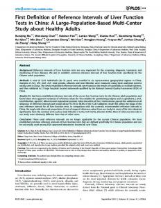
These ab ove m entioned features can b e cal culated wi th IDS s olidification m odel an d Tempsimu heat transfer model of AALTO for defined steel grades of the industrial partners. In t he pr evious na tional pr oject AALTO has m ade a r esearch f or R uukki Raahe S teelworks f or optimising the Submerged Entry Nozzle (SEN) in continuous casting. The effect of different parameters on th e s teel f low in th e m ould, w ere i nvestigated. According t o th e f luid f low s imulations, c ritical parameters or features were determined. Critical parameters were surface velocity in the mould (Figure 1-1a), surface wave height (Figure 1-1b), turbulent kinetic energy, impinging velocity penetration depth of SEN. Safety ranges for these critical parameters were derived in order to obtain good as-cast quality (Table 1-4). In the following are results from the research. 24
SEN1,-15 deg SEN1+5mm,-10deg SEN1+5mm,-15deg SEN1+5mm,-20deg SEN+10mm,-10deg SEN+10mm,-15deg SEN+10mm,-20deg
0.3
SEN1,-15 deg SEN1+5mm,-10deg SEN1+5mm,-15deg SEN1+5mm,-20deg SEN+10mm,-10deg SEN+10mm,-15deg SEN+10mm,-20deg
22
Surface wave height, mm
Surface velocity, m/s
0.35
0.25
20 18 16 14 12
0.2
10
1.2
1.3
1.4
1.5
1.6
1.7
1.2
Casting speed, m/min
1.3
1.4
1.5
1.6
1.7
Casting speed, m/min
Figure 1-1. Dependency of steel a) surface velocity and b) free surface wave height on casting speed. Mould: 1.75mX0.175m. Immersion depth: 140 mm. SEN type: sen1, sen1+5mm, sen1+10mm. Nozzle port: 85X(45,50,55). Nozzle angle: -10, -15, -20 degree. Casting speed: 1.40, 1.55, 1.70 m/min.
Table 1-4. Determined critical parameters and safety ranges for them.
Critical parameters
Safety ranges
Surface velocity [m/s]
0.2-0.3
Surface wave height [mm]
10-20 2
2
Turbulent kinetic energy [m /s ]
0.025-0.04
Penetration depth [m]
2.0-4.0
Impinging velocity [m/s]
0-0.25
DUFERCO collected influencing factors for the main surface defects on castings (Table 1-5).
Table 1-5. Influencing factors to the main surface defects.
21
2.3.2 WP2 SIMULATION OF MOULD POWDER BEHAVIOUR The m ain o bjective of t his WP w as t o develop m odels t o s tudy t he m ould pow der phe nomena ba d casting q uality an d t o d etermine i mportant f eatures an d s afety ranges f or t he q uality co ntrol. DUNAFERR studies heat t ransfer p henomena of t he s trand. T he p artners i n t his WP ar e CSM, BFI and DUNAFERR. The models will be applied for industrial validations and testing in WP5.
Task 2.1 Thermal transient model of powder heating and melting (CSM) CSM has carried out the development of “Liquid pool model”, which is able to simulate the heating and melting of the mould lubricating powder on the meniscus. It is able to calculate the time evolution of liquid, sintered and powder layer thicknesses on the meniscus. This model is based on the work carried out b y Nakano et al . [12] and was formerly de veloped w ithin t he g eneral pur pose F EM c ode MSC.MARC. It was a 1D thermal model able to compute also the displacements related to the density variation of the material induced by the sintering reaction. In this respect, the model is non-linear, because the thermal field depends on the thicknesses of the three layers, which, in turn, depend on the temperature, through the density. In the model, the sintering reaction is described via a kinetic equation representing the time and t emperature ev olution of t he void fraction of t he material, wh ich t he t hermophysical p roperties depend from. The main input data for the “Liquid pool model” are listed in Table 2-1. Table 2-1. Main input data for the “Liquid pool model”.
id 1 2 3 4
consumption meniscus sinterisation [kg/ton] temperature [°C] temperature [°C] 0.25 0.1 0.25 0.25
1525 1525 1553 1525
1000 1000 1000 900
size [mm]
casting speed [m/min]
initial powder thickness [mm]
200*200
1.6
100
“The Liquid pool model” has been upgraded by including the capability of simulating powder additions during c asting. T his t ask ha s be en a ccomplished b y w riting a us er s ubroutine w ithin t he FEM c ode MSC.MARC a nd b y m odifying th e s tructure o f th e M SC.MARC in put f ile. As a r esult o f th e m odel
22
‘revamping’, the computational domain includes the initial powder layer and all the layers subsequently added (the number of additions in the simulation is defined in advance). At run start, (“initial state” in Figure 2-1), only the domain portion representing the initial powder layer is “act ive”. On t he t op, t he h eat t ransfer b etween p owder s urface an d am bient i s r epresented as boundary condition (“boundary A”). The thermal and phase evolutions of this layer are simulated until the first addition occurs, including powder consumption. At t he t ime o f po wder a ddition, t he domain po rtion c orresponding t o t he a dded powder l ayer i s activated and the boundary condition A is moved on the top of it. Accordingly, the user subroutine for the calculation o f t he o utput v ariables ( thickness o f t he l iquid, s intered a nd po wder l ayers) ha s be en modified in order to account for the powder additions. An e xample of o utput i s s hown i n Figure 2-2, c onsisting o f th e results in te rms o f each la yer le vel present on the meniscus: liquid slag, sintered material and powder at the base state. Further i mprovements i n t he CSM’s "Liquid pool m odel" ha ve c onsisted o f a c alibration s tage a nd testings with the available pool height measurements.
Figure 2-1. Sketch of the simulation of powder addition in CSM “Liquid pool model”.
Figure 2-2. First simulation with CSM enhanced “Liquid pool model”, including powder additions.
The following actions have been made for improving the model:
23
Introduction o f a t emperature-dependent s interisation k inetic ( void r atio β as a f unction o f time)
(
β = β 0 ⋅ 1 − K (T ) t − t0 where
β0
)
3
with K (T ) = a ⋅ e
is the initial void ratio,
−
Es R⋅T
(1)
K (T ) is the sinterisation reaction rate with activation energy
ES (with a fitting parameter), t 0 is the sinterisation start time.
Modification o f t he de nsity de pendence o n t he v oid r atio β , ch anging i t f rom a wei ghted average behaviour to a step behaviour, the latter being more representative of powder heating and m elting d ynamics. It can b e d escribed as f ollows: the c arbon f ilm e ntraps t he po wder molten p articles u ntil i t i s co mpletely b urned; the m elt p owder s tarts t o b ehave as a co herent liquid only when sinterisation is almost complete ( β liquidus
Actual roll gap
117
liquidus>T>solidus
T3%; • INDEX 2 when ≥ 1 % the variation of level > 5%; • INDEX 3 when ≥ 1 % the variation of level > 10 %;
Surface q uality in dex, m ean v elocity with its s tandard deviation a nd id entification is a utomatically reported. To follow and measure this index traceability of the billet is assured by identifying the billet before rolling with billet marking. In that way a c orrelation with the defects on wire and the process of the billet can be made.
Casting experiments at CAS CAST T RIALS - CAS has pe rformed c ast t rials w ith t he i nstrumented mould de scribed i n Task 5 .1. (installed b y CSM staff). T he e xperimental d ata s hown here refer t o t he s teel F304L1, wi th cas ting speed 1 .5m/min, an d a cal culated ( from wat er t emperature m easurement) average h eat f lux of 1.69MW/m2. Figures 5-5 show the temperature profiles achieved along two adjacent section levels. DATA A CQUISITION - A r easonable q ualitative d istribution i s a chieved in b oth c ases, w ith thermocouples at face cen tres b eing ‘hotter’, an d the corner ‘colder’. This aspect can b e amplified by the t ypical n ozzle geometry, wi th f our l ateral h oles (together w ith a b ottom h ole) (see Figure A -2 in Appendix) with the impact stream coming from the nozzle hits directly the mould sides. Examples of thermocouple average measurements are given in Figure 5-6. SAMPLE COLLECTION F OR M ICROSTRUCTURAL A NALYSIS - Sample co llection h as b een carried out by CAS both on as-cast billets and on rolled products to assess the presence of defects. The ghost line defect class has been investigated, consisting on dark lines at some depth below the surface [25] on the macro-etched sections of cast billets, mainly corresponding to the secondary cooling region. The d arkness of the line reveals the segregation of some alloy elements. Sub-surface cracks can open [26] at steel grain boundaries from the ghost line during primary and secondary cooling because of the hot-tearing (triggered b y the stress dynamics). Furthermore, sub-surface cracks can open up to surface during subsequent plastic deformations.
55
a)
b)
Figure 5-5. a) Distribution of the thermocouples at 120mm from meniscus and the corresponding temperature time evolution. ). Distribution of the thermocouples at 180mm from meniscus and the corresponding temperature time evolution.
Figure 5-6. 160*160mm2 mould thermocouple signals from F304L1 heats (left) and 420A7 heats (right).
Table 5-2 shows the list of the heats interested in this analysis and the main casting parameters. Table 5-2. Steel CAS F304L1 - Main casting parameters, common (on average) to all the heats considered.
steel F304L1
casting speed [m/min] 1.5
tundish weight [ton] 16
water flux rate [m3/h] zone x1
zone y1
zone x2
zone y2
zone x3
zone y3
0.8-1.0
0.8-1.0
0.9-1.1
0.9-1.1
0.6-0.8
0.6-0.8
56
Figure 5-7 shows the etched surface of the billet samples (HCl diluted / 20min).
Figure 5-7. CAS steel sizes 160*160mm2 a) steel F304L1: absence of observed defects; b) steel 420A7: redevidenced defects in the off-corner regions.
STEEL F304L1 C AST B ILLETS - The s teel F304L1 c ast bi llets s hows no s ub-surface d efects; the solidification structure is completely columnar from the surface to the billet centre. STEEL F304L1 R ODS - The r ods h ave b een i nspected at t he o ptical m icroscope t o s earch d efects. Straight longitudinal (SL) defects have been observed on steel F304L1 heat 72887 (Figure 5-8): 5 of 13 rods are affected; the defects are 0.08-0.15 mm deep and distributed irregularly in different locations.
Figure 5-8. Steel CAS F304L1, heat 72887: a) surface straight-longitudinal defect; its depth is 0.08-0.15mm; not continuous; rods affected 5/13; b) locations on the rods.
STEEL 4 20A7 C AST B ILLETS - Contrary to s teel F304L1, s teel grade 420A7 of s ize 160*160mm2 show s ubsurface cr acks, m ainly located i n t he o ff-corner r egion, s eldom i n t he m iddle o f t he s ide (Figure 5-9). On average, the distance of the cracks from the external surface is 14-15mm. The external chill zone is n ot evident while th e white b and generated b y th e final stirrer is well visible. Five h eats have been considered: 872971, 972463, 72034, 72622 and 73012. Typical main casting parameters of the heats are listed in Table 5-3.
57
Figure 5-9. Typical internal crack in billets of martensitic peritectic resulphurised 420A steel.
Table 5-3. Steel CAS 420A7 – Main casting parameters, commons (on average) to all the heats considered.
steel 420A7
casting speed [m/min] 1.4
tundish weight [ton] 16
water flux rate [m3/h] zone x1
zone y1
zone x2
zone y2
zone x3
zone y3
0.5-0.7
0.5-0.7
0.6-0.8
0.6-0.8
0.4-0.6
0.4-0.6
In the Tables A -4 - A-8 (in Appendix), CAS has reported d ata ab out “ghost lin e” d efect class on the heats c onsidered: c asting l ine i d., bi llet slice i d. i nspected, t he a mount of de fects s ites found a nd t he corresponding maximum depth, severity and position from the edge. STEEL 420A7 RODS - Straight longitudinal defects have been observed in all t he steel 420A7 rods; they are of two types (Figure 5-10), the type 1 is 0.08-0.09 mm deep, the type 2 is max 0.35 mm deep; both of these types are distributed not continuously in different locations. Surface cracks have been observed in the rolled rods for both steels but with a higher incidence for steel 420A7 t han for s teel F304L1, w hich c ould be a first c onfirmation of t he de rivation of s ome of t hese defects from the sub-surface cracks previously open in the billets.
Figure 5-10. Steel CAS 420A7 heat 073012: surface straight-longitudinal defect; its depth is 0.08-0.09mm (type 1) and 0.35mm max (type 2); not continuous; rods affected 4/4.
58
DUNAFERR carried o ut cas t t rials t o s tudy t he ef fects o f p rocess p arameters o n t he centreline segregation an d on the surface quality. All important p rocess d ata were recorded for the validation of the mathematical m odels. Thin cross-sections were cu t from the selected slabs for further macro- and microstructural investigations. During sample collection the surface quality of the slabs was inspected. Two typical slab defects found are shown in Figure 5-11.
Figure 5-11. Typical surface defects at DUNAFERR a) transverse crack, b) star crack.
As a result of the cast trials a large variety of slab samples was available with known casting parameters for f urther microstructural i nvestigations. It c an b e s tated t hat t he Ni co ating greatly d ecreased t he surface quality problems of the slabs. The number and the size of the star cracks were much smaller on the surface o f the slabs as a result o f the Ni c oating (see Table 5-4.). Evaluating th e c ollected d ata it became p ossible t o d emonstrate t he e ffect o f s uperheat an d cas ting s peed m odification o n t he mould temperature di stribution a nd o n t he s trand s urface t emperature. Figure 5-12 s hows t he ef fect of superheat on the surface temperature of the strands measured by line-scanner. Table 5-4. Comparison of surface defects on slabs cast in the moulds with and without Ni-coating.
Figure 5-12. The effect of superheat on the surface temperature of the strand.
59
Cast trials at DUFERCO Main f eatures of DUFERCO billet ca ster h ave b een c ollected an d r eported t o allow t he m odel simulation planned in this research project. DUFERCO performed specific analysis focused to improve the surface quality. The main defects in the chosen s teel g rades h ave b een i dentified b y d ifferent ap proaches: t heoretical point o f view, visual inspection o f b illet surface an d m etallographic ex amination. T he cr itical d efects f or ap plications o f cold-heading steels have been identified as well as the promising casting practices. Defects which are critical for cold-heading applications are: • Depressions • Bleeding • Mini break-out • Craze cracks • Pin-holes (also with high carbon steel grade)
1.Critical Steel Grades: cold-headed steels (C-Mn-B-Ti) DUFERCO focused in this project on critical cold heading grades C-Mn-B-Ti, mainly on 20MnB4 and 30MnB4. Other steel grades belonging into this critical group steels were 19MnB4, 23MnB4. Defect mechanism: In these grades a coarse austenite grain grows at the surface. The presence of high level of n itrogen, aluminium, b oron in duces a low h ot d uctility at b ending p oint of caster resulting in transversal cracks in the billet corners. The wire rod is characterised b y high density of laps and poor rate of up-setting test. In Table 5-5 two heats were chosen for an example of the secondary cooling effect on defects. Casting parameters and calculated Ferrite potential (Task 5.5) values are given in Table 5-6. Typical defect on billet and its evolution in wire rods is in shown in Figure 5-13. Table 5-5. Steel compositions of example heats 41334 and 69469 in C-Mn-B-Ti steel grade.
Heat C Mn S P Si Cu Al Ca Ni Cr Mo N B Ti 69469 0.20 0.93 0.006 0.011 0.048 0.053 0.028 0.002 0.042 0.24 0.007 0.0082 0.0003 0.027 41334 0.20 0.93 0.002 0.011 0.06 0.061 0.035 0.001 0.048 0.058 0.01 0.0088 0.0003 0.035
Table 5-6. Casting parameters of heats 41334 and 69469 of steel grade C-Mn-B-Ti and calculated Ferrite potential (FP) values.
CP 0.20 0.21 Superheat Speed Frequency Stroke Taper
FP 0.76 0.72 ΔT vc f convex
60
Heat 69469 41334 35 2.3 150 8 0-700
Grade 23MnB4 19MnB4 °C m/min c/min mm t
a)
b)
c)
Figure 5-13. Evolution of defect: a) billet surface edge, b) cross section (billet) c) wire rod (cross section).
Operational countermeasure: A m ethod o f p reventing a t ransverse cr acks i s t o av oid a b rittle temperature r ange at b ending an d straightening. T he ch anges o f t he s econdary c ooling p attern ( to increase b ending t emperature > 950°C a t c orners from m enu C t o menu H w as adopted (Table 5-7). This n ew o perational p ractice h as b een applied wi th g ood r esults in t erms o f u p-setting r ate te st. But this pattern of secondary cooling induce the craze cracking when the steel contains high level of tramp elements as (Cu, Sn, As). Surface temperature was low enough that AlN was n ot formed a voiding i ts effect on lowering ductility. Table 5-7 Secondary cooling menu C and H of DUFERCO (casting speed 2.2 m/min).
Cooling menu C zone W [l/min] W [m³/h] p [bar] Z0 158 9.50 2.91 Z1 128 7.70 1.24 Z2 97 5.80 1.66
Cooling menu H zone W [l/min] W [m³/h] p [bar] Z0 112 6.72 1.46 Z1 110 6.60 0.91 Z2 80 4.80 1.13
[l/kg] 0.46 0.37 0.28
[l/kg] 0.33 0.32 0.23
The co ld h eaded steels are hi gh a dded v alue qua lity grades a nd n o cr acks ar e allowed o n t he f inal product. DUFERCO modified s craps menu, s et t he m aximum a ge o f 1000 t ons for mou ld and decreased s econdary c ooling b y ch anging i ts s econdary c ooling m enu f rom C t o H ( Table 5-7). Al so grinding was i ncreased i nto 4 f aces of each b illet an d ad ditional cu ts ar e m ade at t he wi re rod m ill. Macroetched samples in Figure 5-14 show the impact of secondary cooling (menu C vs. H) on internal quality o f th e b illet ( 23MnB4). After t hese above m entioned modifications, th e q uality of th e c oldheaded wire rods raised up: up-setting test of good quality increased from 81% to 95%. Heat 69469 (menu C)
Heat 45679 (menu H)
Heat 45680 (menu H)
Figure 5-14. Macroetched billet samples with cooling menu C and H.
61
Additionally some slices of bi llets of 19MnB4 grade were cu t on wh ich co rner cracks could be s een (Figure 5-15) (cooling menu H ). Th ree samples wer e i nvestigated, f rom l eft: near t he co rner wi th cracks, n ear t he c orner wi th d eep o scillation m arks, an d o ne i n t he m iddle f ace wi th d eep o scillation mark. A regular structure of solidification without any major perturbation can be seen on macroetched sample (Bechet-Beaujard etching). The solidification horn is almost non-existent despite the presence of high de pression o n the sample 503702-1. In SE M in vestigations o nly iron oxides wer e ch aracterised from the cracks. (Figures 5-16 and 5-17).
Figure 5-15. Macroetched billets of steel grade 19MnB4 (cooling menu H).
Figure 5-16. SEM investigations on cracks over 10 mm on billet surfaces in steel grade 19MnB4.
62
Figure 5-17. SEM investigations on cracks over 3 mm on billet surfaces in steel grade 19MnB4.
With these C-Mn-B-Ti steels decreasing the amount of water in the secondary cooling have had benefit on the surface quality but for some grades, for example for the grade 20MnB4 (for chain applications), cooling menu H (Table 5-17) has not been enough. A new cooling menus J (0.83 l/kg at 2.2 m/min) was tested. Each b illet was r olled after grinding the co rner an d controlled. The rejection rate of wire r ods due to surface defect changed from one heat to another. Table 5-8 summarises the casting operation and quality of the steel grade 20MnB4 at DUFERCO. Casting p arameters (cooling, casting speed, mould powder etc.) were adapted as a result of quality improvements (lower rejection percentage of wire rods).
63
Melubir 3011
80
17101
Melubir 3011
80
5.7.2011
29.8.2011 17147 SYNTHERM GB 1022/M 80
3.9.2011
17153 SYNTHERM GB 1022/M 80
28.10.2011 17204 SYNTHERM GB 1022/M 78
12.11.2011 17227 SYNTHERM GB 1022/M 80
46 27 21 41 16 47 30 23 29 49 31 31 36 30 33 36 27 28 56 33 20 18 50 41 29 27 56 43 33 22 32 48 37 22 18
0.875 0.725 0.886 0.5 0.571 1.347 1.125 1.089 1.13 1.381 1.583 1.419 1.375 1.34 1.024 0.975 0.814 0.705 0.917 0.833 1.122 1.195 0.542 0.5 0.553 0.564 0.604 0.786 0.767 0.683 0.827 0.395 0.2 0.175 0.239
90.56 86.395 75.596 86.395 75.356 100.346 98.298 92.155 94.203 86.011 98.298 88.059 98.298 96.251 86.011 91.915 88.059 96.443 86.011 98.298 100.346 83.963 93.691 105.69 91.739 76.124 98.298 86.011 88.059 83.963 106.49 88.059 92.155 81.915 94.203
5.16 22.1 27.01 15.74 5.82 11.79 17.44 38.37 0 2.33 12.21 3.05 12.54 14.44 2.17 0 4.65 0 0 3.76 7.52 0 0 0 0 1.95 14.14 2.33 0 0 7.51 12.85 14.86 14.65 3.91
speed (m/min)
5 1.9 H 5 2.2 H 5 2.3 H 5 2.3 H 5 2.3 H 6 2.1 H 6 2.3 H 6 2.3 J 6 2.3 J 6 1.9 H 6 2.2 H 6 2.3 H 6 2.2 H 6 2.2 H 6 2.3 H 5 2.2 H 5 2.3 H 4 2.3 H 6 1.7 J 6 2 J 6 2 J 6 2 J 6 2 J 6 2 J 6 2 J 6 2 J 6 1.8 H 6 2 H 6 2 H 6 2 H 6 2 H 6 1.8 J 5 2 J 5 2.05 J 5 2.1 J
# active lines
% of discard
20.6.2011 17074
tons produced
82
0.105 0.158 0.158 0.060 0.060 0.045 0.053 0.079 0.058 0.047 0.078 0.073 0.048 0.049 0.069 0.041 0.054 0.045 0.084 0.054 0.081 0.072 0.087 0.102 0.080 0.073 0.098 0.108 0.000 0.104 0.089 0.107 0.069 0.054 0.076
index of the level of steel in the mold
Melubir 3011
0.732 0.709 0.781 0.742 0.759 0.756 0.813 0.734 0.755 0.728 0.757 0.74 0.752 0.749 0.778 0.764 0.745 0.716 0.769 0.723 0.753 0.751 0.756 0.715 0.743 0.767 0.793 0.787 0.751 0.75 0.738 0.776 0.728 0.789 0.768
superheat
17045
1.6.2011
53187 53185 53186.1 53188 53189 54372 54373 54374 54375 54793 54794 54795 54796 54797 54798 55134 55135 55136 55665 55664 55666 55667 55773 55774 55775 55776 56317 56318 56319 56320 56321 56509 56510 56511 56512
cooling menu
81
Cueq
Melubir 3011
FP
10.4.2011 16957
heat nr.
mold flow (m³/s)
Mold Powder
Sequence nr.
date
Table 5-8. A summary of the casting operation and quality of the steel grade 20MnB4 at DUFERCO.
In the end of 2011 DUFERCO produced 30MnB4 grade. To check the quality the billets were ground after casting and up-settings tests were made on head and tail of each coil. Each coil with a bad result was r ejected. T able 5-9 shows a s ummary of t he cas ting operations an d q uality of t he s teel g rade 30MnB4.
64
# active lines
speed (m/min)
cooling menu
superheat
index of the level of steel in the mold
tons produced
0.52 0.498 0.555 0.484 0.502 0.479 0.498
0.031 0.049 0.027 0.05 0.036 0.042 0.043
6 6 6 6 6 6 6
1.8 2 2 1.8 2 2 2
J J J J J J J
59 41 39 50 46 36 36
0.667 0.381 0.455 0.786 0.708 0.683 0.692
92 92 83.3 92 105.2 89.8 87.6
% of discard
Cueq
56463 10.11.2011 17221 SYNTHERM GB 1022/M 80 56462 56464 56705 56706 7.12.2011 17263 SYNTHERM GB 1022/M 81 56707 56708
FP
heat nr.
mold flow (m³/s)
Mold Powder
Sequence nr.
date
Table 5-9. A summary of the casting operations and quality of the steel grade 30MnB4.
10 11.9 6.1 0 0 5
2. Critical Steel Grade C10 (C-Mn-Ti peritectic steel) C-Mn-Ti is the second critical steel grade group which DUFERCO investigated in this project (Tables 5-10 and 5-11). The surface of this grade is characterised by a coarse austenite grain size. High level of nitrogen induces a rich AlN precipitation along the grain boundaries. Under a low strain rate at bending point of caster the surface is subjected to embrittlement along the austenite grain boundary (hot ductility of this steel deteriorates). The first countermeasure of preventing a transverse cracks was to avoid a b rittle temperature range at bending and straightening of the billets. Up-setting test rate of the wire rod was improved by increasing secondary c ooling from menu C (1.11 l/kg) to menu A (1.22 l/kg) (Table 5 -12). Cracks in th e b illets with the secondary cooling menu C are shown in Figure 5-18. New concept for transverse crack prevention The hot ductility can be improved by rapid cooling until the δ + γ phase region and reheating up to δ region. This thermal history is able to produce a layer with idiomorphic ferrite. By avoiding the ferritelike film (ferrite along austenite grain boundary) hot ductility of the steel grade is improved. At the exit of m ould i t i s possible t o produce a t hickness o f 0. 5-2 m m o vercooled b y S SC ( Surface S tructure Control) (from 1080° C t o 800° C w ith cooling rate a bout 7° C/s) us ing a hi gh w ater f low r ate a fter natural reheating to 950°C. Table 5-10. An example composition of peritectic C-Mn-Ti steel grade.
C Mn S P Si Cu Al Ca Ni Cr Mo N Ti 0.092 0.44 0.008 0.014 0.025 0.061 0.031 0.002 0.044 0.056 0.007 0.008 0.017
65
Table 5-11. Casting parameters of C-Mn-Ti grade and calculated Ferrite potential (FP).
CP
FP
0.09
1.02
Heat
Grade
Superheat
ΔT
35
°C
Speed
Vc
2.3
m/min
Frequency
F
150
c/min
8
mm
0-700
t
Stroke Taper
Convex
Table 5-12. Secondary cooling menus C and A of DUFERCO (casting speed 2.2 m/min).
Cooling menu C
Cooling menu A
zone W [l/min] W [m³/h] p [bar] [l/kg]
zone W [l/min] W [m³/h] p [bar] [l/kg]
Z0
158
9.50
2.91
0.46
Z0
175
10.50
3.6
0.51
Z1
128
7.70
1.24
0.37
Z1
150
9.00
1.7
0.43
Z2
97
5.80
1.66
0.28
Z2
97
5.80
1.7
0.28
Figure 5-18. Cracks on the C-Mn-Ti grade billets with the secondary cooling menu C.
3.Critical Steel Grade C72D2 (high carbon steel) The third critical steel group investigated at DUFERCO was high carbon steels. The secondary cooling pattern of hi gh carbon steel grade (C > 0.70) was performed b y ha rd cooling. This cooling p attern is aimed t o ach ieve a s trand wi th a mushy z one b etween 2 5-35% a t the final s tirring z one. T his operational r equirement a llows m inimising th e s egregation f or h igh d iameter w ire r od. In o rder t o improve the steel quality DUFERCO increased remarkably the water flow rate from 0 .37 l /kg (menu C) to 1.20 l/kg (menu F) at the second c ooling z one, zone Z1. The compositions of the trial heats are shown in Table 5-13. Heat 68910 was cooled according to menu C and heat 64958 with menu F (Table 5-14). Hard cooling at the caster and a macroetch cross-section of a billet are in Figure 5-19. As a result
66
from a dapting t he c ooling m enu F , t he s egregation i ndex w as i mproved, which can b e obs erved i n Table 5-15. Table 5-13. Composition of the heat with hard cooling (68910) and the heat without hard cooling (64958). Heat 68910 64958
C 0.84 0.83
Mn 0.74 0.73
S 0.007 0.002
P 0.015 0.010
Si 0.29 0.29
Cu 0.043 0.051
Al 0.050 0.034
Ni 0.032 0.040
Cr 0.22 0.21
Mo 0.006 0.005
N 0.0075 0.0067
Cooling menu F menu C
Table 5-14. Secondary cooling menu C and F of DUFERCO (casting speed 2.2 m/min). Cooling menu C
Cooling menu F
zone W [l/min] W [m³/h] p [bar] [l/kg] Z0 158 9.50 2.9 0.46
zone W [l/min] W [m³/h] p [bar] [l/kg] Z0 183 11.00 3.9 0.53
Z1
128
7.70
1.2
0.37
Z1
417
25.00
13.0
1.20
Z2
97
5.80
1.7
0.28
Z2
97
5.80
1.7
0.28
Figure 5-19. a) Hard cooling in zone Z1 and b) Macroetched cross-section of a billet (menu F).
Table 5-15. Segregation index of billet specimens of heats 68910 and 64958 and the reduction of area, Z %, of wire rod (diameter 13 mm). Segregation index: 1 = the best, 3 = the worst), Z (%) = ROA, reduction of area.
Test heat
1
2
3
4
5
6
7
8
9
10
Z (%)
68910 64958
1 3
1 3
1 3
2 3
2 2
1 3
1 3
2 3
1 2
1 2
32 28
67
Task 5.3 Execution of microstructural analyses (DUNAFERR, CSM) CSM have performed microstructural analyses on samples of CAS. An example of a sample is shown in Figure 5-20. Scanning Electron Microscope observations have been made on billet pieces by CSM (Figure 5-21).
Figure 5-20. Example of billet section from which samples were derived for EDS analysis.
Figure 5-21. An example of CSM EDS analysis of CAS samples of steel F304L1.
The i nvestigation p erformed o n t he s amples i ndicated t he p resence o f p owder i n t he m acro-inclusion agglomerate f ound. The related spectra show the p resence of t ypical elements (e.g., Na) associated to powder composition.
68
The indications have confirmed the tendency of such steel - within the operating conditions examined to b e p rone t o p owder s ticking. C ross-correlating the samples an d the heat h istory, t he o ccurrence of such a defect has been correlated to improper powder melting at start of casting. It h as been suggested t o f ind po wders w ith ‘ improved’ c omposition, i n o rder t o f avour t he r apid formation of a reliable liquid pool. It has given further elements for validating the models and finding correlations between melted powder amounts and heat transfer in the mould/steel gap. DUNAFERR analysed t he cen treline s egregation of s everal s labs o f d ifferent c hemical co mposition because centreline segregation is a critical point regarding the slab quality. The macrosegregation of the slabs was characterized by Baumann imprint and macroetching by ammonium persulphate solution. In some cas es at t he cen tral zo ne o f t he s labs ch emical co mposition was m easured as a f unction o f t he distance from the centreline. To characterise the porosity of the centreline of the slabs ultrasonic and xray investigations were carried out on some samples. A systematic examination of metallographic methods for detection of primary steel texture was carried out, b ecause i n s pite o f fast development o f t echnical t ools f or ex amination, t he i mportance of traditional m acrostructural i nvestigation h as n ot d ecreased; o n t he co ntrary, t hese m ethods ar e i n t he state o f t heir r evival. On e o f ev ident r easons f or i t i s t he f act, that t he r esults o f m acrostructural examinations an d t he co nclusions drawn f rom t hem ar e i n t he cl osest r elation w ith t he parameters o f casting technology, reflect their changes and the deviations from the specified values. During t he m icrostructural an alyses of t he co llected s amples DUNAFERR focused on t he s tudy of centreline segregation since segregation can still cause quality problems at some steel grades. A typical Baumann print is shown in Figure 5-22. C entreline segregation was co mpared in slabs an d in 40 mm thick hot plates to investigate the effect of hot rolling on the segregation. It was found that the nature of the segregation did not change during hot rolling and if significant centreline segregation is present in the slab then it can cause quality problem in the hot rolled plates and strips as well. Chemical analyses were carried out to quantitatively characterise centreline segregation (see Figure 5-23). Our ex periments t o ch aracterise t he por osity of t he centreline o f th e s labs b y u ltrasonic o r x -ray methods d id n ot g ive b etter r esults th an th e tr aditional m etallographic te chnique. The r esults o f th e microstructural characterisation were used during validation of the mathematical models.
Figure 5-22. Baumann print of the slab cross-section.
Figure 5-23. Chemical composition as the function of the distance from centreline.The background is the Baumann print of the investigated slab.
69
Task 5.4 Calibration of the models (BFI, CSM, DUNAFERR, AALTO) Calibration o f t he num erical m odel f rom WP2 a nd WP3 a ccording t o relevant i ndustrial da ta a nd collected b oundary c onditions f or one cas t t rail was u ndertaken b y BFI. T he t hermal bo undary conditions f or t he num erical c omputations w here a dapted t o t he c ontinuous s lab cas ter d ata. From temperature measurements conducted by DUNAFERR in WP5 a circumferential average of the mould temperature was evaluated in dependence from the mould height. From this temperature distribution a heat transfer coefficient of 6000 W/m²K was defined and a temperature distribution in the mould was computed i n good a greement t o t he measured t emperature di stribution by DUNAFERR. T he g eneral temperature characteristics m easured b y DUNAFERR, s howing a h igher temperature n ear t he meniscus w as i n g ood a ccordance t o t emperature di stributions m easured i n s imilar m oulds f rom t he literature [3,27,28]. With data from the DUNAFERR slab caster and results from computations from OBUDA University for t he s teady s tate caster t rials t he n umerical c omputations wer e cal ibrated. A n e xample f or t he computed temperature distribution along the strand is given in Figure 5-24. Temperatures at the end of the p rimary c ooling zo ne wer e s tated with ap proximately 1000° C a t t he c orner o f t he s lab a nd approximately 1170°C at the mid wide side. At the end of the secondary cooling zone a temperature of approx. 845°C was given from DUNAFERR. The temperatures computed were in good agreement to the data provided by DUNAFERR (Table A-1).
Figure 5-24. Numerically computed temperature distribution at the centreline, narrow side, wide side and corner of the strand.
LIQUID POOL - The definition of a calibration technique for the "Liquid pool model" has been carried out by CSM starting from the basic idea of not using data from the process to calibrate the parameter a of the sinterisation kinetic (see Equation 1), but deriving it from a measurable property of the powder: the melting rate. Once a is d etermined, the simulation of t he casting p rocess is u sed to verify the model. Figure 5-25 summarises the calibration procedure flowchart.
70
Figure 5-25. Flowchart of the calibration technique for the "Liquid pool model".
The p owder m elting r ate cu rve (melting r ate vs. C FREE ) i s derived b y u sing t he ex perimental d evice shown i n Figure 5-26a. Within th is e xperimental device, a 3m m t hick po wder l ayer i s put o n a S iC plate, heated at 1400°C by a solenoid and the time elapsed until complete melting is measured. At this stage, a simulation has been carried out to verify the calibration technique previously described and to check the "Liquid pool model" functionality. The simulation steps have been: 1. Setting the content o f f ree carbon. From t he ex perimental m elting r ate cu rve, both the g of powder to be melt in the experimental device and the total melting time have been identified. 2. Experiment device has been simulated by the "Liquid pool model"; the kinetic parameter a has been cal ibrated r ecursively, i n o rder t o obtain a v oid r atio ev olution at t he t op of t he p owder layer with a void ratio β ≤ 0.01 at a simulation time equal to melting time. At t he end of the recursive procedure, the calibrated value of kinetic parameter a has been computed (Figure 526b). 3. Calculation of the time evolution of the three layers thickness (base state, sintered and liquid) at the meniscus, as shown in Figure 5-27. As it c an b e n oticed, the model results poorly agree with the measure. It can b e d ue to the following reasons: In adequate calibration of sinterisation kinetic parameter Simulation of regular additions, instead of real ones Liquid p ool h eight m easures a re in trinsically h ighly s cattered. T hen o ne m easure i s n ot representative.
71
Figure 5-26.a) Experimental device for the melting rate curve measurement (used in ECSC project 7210.PR/273, June 2004). b) Simulation of the experimental device - Numerical result obtained at the end of the recursive procedure to calibrate the value of kinetic parameter a
Figure 5-27 - “Liquid pool model” numerical results.
MOULD HE AT F LUX - The c omputed e volution a long t he mould’s he ight of t he he at f lux pr ofile along t he s ection p erimeter i s g raphed i n Figure 5-28. It ha s be en c alibrated t o m ake t he c omputed temperature converge to the measured data at the midface and at the corner (Figure 5-29) for both the steel grades CAS 420A7 and F304L1. The t emperature field r esulting from 3D t hermo-mechanical FEM s imulations o f t he m ould h as b een compared to the experimental data at the corner and the mid-face regions. A good agreement has been found in both the heats of the steels (Figure 5-30).
72
z z z z z z z
= 0m (meniscus) - F304L1 = -0.1m - F304L1 = -0.2m - F304L1 = -0.3m - F304L1 = -0.4m - F304L1 = -0.5m - F304L1 = -0.675m - F304L1
z z z z z z z
specific heat flux [MW / m2]
3.5
3 2.5 2 1.5 1 0.00
0.01
0.02
0.03
0.04
0.05
0.06
0.07
3 2.5 2 1.5 1 0.00
0.08
distance from bar mid-face, along the cross section perim. [m]
0.01
0.02
0.03
0.04
0.05
0.06
0.07
0.08
distance from bar mid-face, along the cross section perim. [m]
thermocouple vertical lines
thermocouple vertical lines
a
mid-face
corner
b
mid-face
corner
Figure 5-28. Evolution of the heat flux profiles along the casting lines; a) heat 72142-72143 of steel CAS F304L1; b) heat 72299-72300 of steel CAS 420A7.
The computed stationary temperature field reached by the mould when submitted to th e h eat flux h as been employed as input for computing the mechanical evolution of the mould itself.
F304L1 - midface - average acquisition F304L1 - corner - average acquisition 420A7 - midface - average acquisition 420A7 - corner - average acquisition
F304L1 - midface - computed F304L1 - corner - computed 420A7 - midface - computed 420A7 - corner - computed
110 100 90
temperature [°C]
specific heat flux [MW / m2]
3.5
= 0m (meniscus) - 420A7 = -0.1m - 420A7 = -0.2m - 420A7 = -0.3m - 420A7 = -0.4m - 420A7 = -0.5m - 420A7 = -0.675m - 420A7
80 70 60 50 40 30 0
0.1
0.2
0.3 0.4 distance from meniscus [m]
0.5
0.6
0.7
Figure 5-29. Agreement of the thermal field between acquisition and computation (FDM model).
73
Mid-face - Experimental
Mid-face - FEM 3D
Mid-face - Experimental
20mm from corner - Experimental
20mm from corner - FEM 3D
20mm from corner - Experimental
temperature at corner [°C] 0
10
20
30
40
50
60
70
80
90
0
-0.1
-0.1
-0.2
-0.2
-0.3
-0.3
-0.4
-0.4
-0.5
-0.5
-0.6
-0.6
-0.7
-0.7 150
60
70
80
90
100
110
120
130
140
10
20
30
40
50
60
70
80
90
100
0.0
Position from meniscus [m]
Position from meniscus [m]
100 0
50
20mm from corner - FEM 3D
temperature at corner [°C]
0.0
a
Mid-face - FEM 3D
temperature at mid-face [°C]
0
-0.1
-0.1
-0.2
-0.2
-0.3
-0.3
-0.4
-0.4
-0.5
-0.5
-0.6
-0.6
-0.7
b
50
60
70
80
90
100
110
120
130
140
-0.7 150
temperature at mid-face [°C]
Figure 5-30. Mould temperature fields at mid-face and 20mm far from the corner. Comparison between the thermocouple acquisition and the results from computation; a) heat of steel CAS F304L1; b) heat of steel CAS 420A7.
Calibration of centreline segregation model (DUNAFERR, OBUDA) OBUDA has ev aluated 7 cas ting t rials p erformed at DUNAFERR. T he t rials an d t he cal culations aimed a t th e c alibration a nd v alidation of c entreline s egregation m odel. T he v alidation b ased o n th e supposed effect of supporting roll gaps on porosity formation and mushy liquid flow in the centre of the slab. This effect plays important role in the last stages of slab solidification according to the results of previous experiences and calculations. In this report the results of only one trial will be discussed. For this industrial trial steel with the following chemical composition was chosen (Table 5-16). Table 5-16. Chemical composition of the investigated steel.
This heat was cast into two strands on the vertical slab caster of DUNAFERR. The casting parameters of the strands were identical, i.e. the casting rate, the primary and secondary cooling intensities and the superheats were the same. The only difference between the two strands was the setting of the supporting rolls a long t he c asting machine. T he original r oll s etting w as applied f or t he strand no . 1 a nd t he modified setting for the strand no. 2 according to the Figure 5-31.
74
Figure 5-31. Setting of the original and the modified supporting roll gaps along the strand.
The expected porosity and the characteristics of mushy liquid flow were calculated for both strands by LMI – Liquid M otion Intensity m odel. F or th e c entreline o f s labs th e calculated p orosity l evels ar e given i n Figure 5-32. T he m odification of gaps im proved a little b it th e le vel of c entreline porosity, which decreases the level of centreline segregation.
Figure 5-32. Calculated porosity levels in the case of the original and the modified roll settings.
The o ther f eature o f cen treline s egregation f ormation i s t he flow r ate f unction of m ushy liq uid in t he mushy part of strand. The flow rate functions are given in Figure 5-33.
75
Figure 5-33. Mushy liquid flow rates in the centreline region with the original and the modified roll settings.
From the viewpoint of centreline segregation the low positive value of flow rate is favourable. In this case the final level of flow rate at about 6 meters (6000 mm in Figure 5-33) from meniscus level (i.e. at the boundary of liquid and mushy centre area) the flow rate becomes lower in the case of modified roll setting, but the maximum value of flow rate inside the mushy part of the strand is higher than in the original case. Taking into account both the calculated porosity and the flow rate a small improvement in centreline segregation can be expected as a r esult of the roll setting modifications. Figure 5-34 shows the centreline segregation in the slabs. The improvement in the segregation level can be clearly seen.
Figure 5-34. Etched cross-sections of the centre area of the cast slabs a) on the left the original taper and b) on the right the modified taper.
Calibration of creep model (DUNAFERR, OBUDA, College of Dunaujvaros) For calculation of stresses and strains in the slab surface and subsurface area mathematical model based on phe nomenological e quations ha s be en de veloped (Task 3.7). In order t o c alibrate a nd validate t he model, s ix tr ials u nder w ell-defined p arameters wer e p erformed b y Gleeble 3 800 t ype t hermomechanical s imulator at College of D unaujvaros. The Gleeble 3 800 g ives th e possibility to p erform creep tests as strain or stress controlled p rocesses. Among the six trials two wer e controlled b y st ress and i n f our cas es s train was t he co ntrolling p arameter. T est material i n al l cas es was as -cast St5 2-3. Before creep tests the heating rate was 10°C/s, soaking time 1 min.
76
During t he t wo s tress-controlled tr ials th e c ontrol s ystem w as n ot a ble to stabilise th e s tress le vel, therefore en ormous f luctuations o f t he s tress s ignal wer e d etected. T he ef ficiency of p rocess co ntrol seemed to be much better in strain-controlled cases. All the four trials were successful and gave realistic results. T he s tress f unction co mpared t o t he cal culated v alues a nd t he s tress-strain c urves pr oved t he reliability of Kozlowski’s no. 2 model [22]. AALTO has previously validated IDS m odel with th e r esults o f m any experiments f rom lite rature performed with steel grades of wide compositional ranges [17-20]. Heat transfer boundary conditions in Tempsimu and CastManager models have been validated with experimental data. In modelling, detailed boundary condition options were used, meaning that heat transfer coefficients were given separately for water sprays, rolls and the area where no water or roll is present, only air convection and radiation as a boundary condition. Values in the Figure 5-35 were used. Formula for water sprays: h=aWb h= heat transfer coefficient [kW/m2°C] W=water flow rate [m3/h] Water-only sprays:a=0.11 and b= 0.64 Water-air sprays: a=0.13 and b= 0.72 Heat transfer coefficient for air convection: 0.02 / =°5 mm and temperature 25°C Rolls: contactk area Solid rolls 0.3 kW/m , internal cooled rolls 1.3 kW/m
Figure 5-35. Heat transfer values used in Tempsimu and CastManager models. Values from experiments in [29-31].
Task 5.5 - Definition of critical variables CSM and CAS has found the following critical issues on steel quality: Fluid-dynamics (criteria for slag entrapment at meniscus) Internal structure/solidification (segregation and hot-tearing) FLUID-DYNAMICS AT MENISCUS - According to the experience of CSM, there are critical velocity values that result to be risky for some defects occurrence. Above the critical value at meniscus ease the slag-steel emulsification [32]. Above the critical value at hot spot ease the shell ‘washing’, up to breakout risks [33]. INTERNAL STRUCTURE - SEGREGATION - Relationships between segregation index and equiaxed zone are derived from literature [34] as in Figure 5-36. In this way, superheat and segregation index can be related, and the data arising from experimental work of CAS can be fitted to limit the overheat range and to support the overall on-line process model.
77
Correlation between segregation index and process parameters via steel internal structure features Variation of maximum degree of centerline segregation of carbon with equiaxed zone ratio in high carbon steel billets.
Variation of equiaxed zone with superheat of liquid steel in continuously cast high carbon steel billets.
Figure 5-36. Indication of possible correlation between segregation index and process parameters.
INTERNAL STRUCTURE - HOT TEARING - The off-corner of billet is the region between the corner and the point along the billet transverse-section perimeter where the computed gap is minimum; the gap profile de termines a r eduction i n he at f lux g oing f rom m id-face t o t he co rner, r esulting i n a surface temperature peak in the off-corner region, the local shell thinning and the generation of tensile stress in the solidification front. In the solidification front region of the off-corner itself a tensile stress peak is observed: this scenario is a warning for potential defects (Figure 5-37).
Figure 5-37. FEM profiles of interest for identifying the critical parameters.
78
With respect t o this m echanism o f d efect formation, a critical p arameter can b e identified in the h eat flux profile derived from the temperatures measured in the mould. Steel F 304L1 - The s teel F 304L1 r esists th e s tresses i nduced by th e s olidification, r esulting in th e absence of observed defects (Figure 5-8a in Task 5.2). Steel 420A7 - To verify the mechanism identified with the analysis performed on steel F304L1, further analyses on steel 420A7 have been performed with the aim of confirming that the mechanism is able to induce defects observed in different steel classes (Figure 5-8b in Task 5.2).
Task 5.5 Definition of safety ranges (BFI, CSM, DUNAFERR, AALTO) Certain cr itical p arameters wer e i nvestigated f rom BFI which wer e r elated t o d efects an d p roduct quality. As an example mould flux entrainment was one of the primary sources of surface and internal defects in continuous casted steel products [35]. The m ost c ommon m echanism f or t he e ntrainment o f l iquid f lux i n t he m ould o f a c ontinuous s lab caster was b y f luid f low n ear t he s teel m elt/liquid f lux i nterface. T he s teel m elt f low cam e from t he SEN ports and was redirected by the narrow sides of the mould towards the interface. At the interface between the two fluids a wave developed. When near the interface the shear rate of the steel flow was great and a critical velocity was exceeded emulsification of liquid mould flux droplets occurred, like it was observed in the physical measurements. Such a critical velocity was computed from a f orce balance between the internal force of the steel melt stream and the buoyancy force of a mould flux droplet from Equation 5. A critical velocity of 0.39 m/s for the melt flow was computed. But it was observed from physical modelling that unsteady fluid flow phenomena led to a droplet entrainment occurred at lower flow velocities than the critical velocity at the interface [36,37]. Therefore, the safety ranges for the liquid flux thickness, turbulent kinetic energy, surface velocities and surface wave heights at the interface were evaluated as presented here from all the results obtained from exact s olution of p hysical la ws, o bservations in th e p hysical m odelling a nd th e r esults f rom th e numerical computations (Table 5-17).
Table 5-17. Critical parameters and safety ranges derived from the fluid flow investigations of BFI. [38,39]
Critical parameters
Safety ranges
Minimum Liquid flux thickness
8 - 10 mm
Maximum Surface velocity
0.2 – 0.4 m/s
Maximum Surface wave height
15 – 20 mm
Two c ritical p arameters w ere d efined b y OBUDA for ch aracterising t he centreline s egregation: the porosity and relative flow rate of the mushy liquid. These two parameters depends on the chemistry of steel, on technological data of casting process and – very sharply – on the setting strategy and condition of supporting rolls. The LMI model takes into account these parameters and calculates porosity (Table 5-18) and on mushy liquid flow rate parameter (Table 5-19).
79
Table 5-18. Critical parameter: porosity level in the centre part of slab.
Critical parameter
P [mm2], Porosity level in the centre part of slabs
Defects controlled
porosity, centreline s egregation, centreline di scontinuity i n t he s lab a nd a s a result discontinuity in the centreline of hot rolled strips and plates Remark: centreline s egregation i s cau sed p artly b y p orosity an d p artly b y macrosegregation in the centre part of slab
Determination – LMI (Liquid Motion Intensity) 2D model calculation method Mathematical m odel f or d etermination of s hrinkage a nd pl astic de formation of solidifying shell taking into account the following parameters: • • • • • •
Shrinkage of shell due to solidification and cooling Nominal position supporting rolls (nominal tapering) Real position of supporting rolls (measured by roll checker) Misalignment of rolls Eccentricity of rolls Bulging of shell between rolls
Calculation t he v alue o f v olume ch anges d ue t o s hrinkage an d plastic deformation in that mushy area of the slab (mushy liquid/mushy ratio lower than 0.3), where the free flow of mushy liquid is highly retarded. Safety range
On t he basis o f t heoretical co nsiderations w hich ar e i n r elative g ood accordance with t he a vailable e xperiences co ncerning t he DUNAFERR casting machine P =< 6: small risk of porosity, it can be eliminated by hot rolling P > 6: high risk of porosity, generally cannot be eliminated by hot rolling Remark: t he el imination o f cen treline po rosity hi ghly de pends o n t he thickness of rolled product
80
Table 5-19. Critical parameter: Relative flow rate of mushy liquid in the centreline of slab.
Critical parameter
F [mm/mm], Relative flow rate of mushy liquid at the liquid/mushy boundary in the centreline of slab
Defects controlled
macrosegregation, centreline segregation, macrosegregated centreline area of slab and as a result centreline segregation in the hot rolled strips and plates (in general higher carbon, manganese and sulphur content in the centre part than the nominal values) Remark: centreline segregation is caused partly by porosity and partly by macrosegregation in the centre part of slab
Determination – calculation method
LMI (Liquid Motion Intensity) 2D model Mathematical model f or d etermination of s hrinkage an d p lastic d eformation of solidifying shell taking into account the following parameters: • • • • • •
Shrinkage of shell due to solidification and cooling Nominal position supporting rolls (nominal tapering) Real position of supporting rolls (measured by roll checker) Misalignment of rolls Eccentricity of rolls Bulging of shell between rolls
Calculation the value of relative flow rate of mushy liquid in that mushy area of the s lab ( mushy l iquid/mushy r atio hi gher t han 0 .3), wh ere t he f ree f low o f mushy liquid is not retarded. Safety range
On the basis of theoretical considerations which are in relative good accordance with the available experiences concerning the DUNAFERR casting machine 0 < F < 0.001: small risk of centreline macrosegregation, the macrosegregated mushy liquid is a little bit squeezed out from the mushy area, the mushy liquid moves in the direction of the meniscus inside the slab. F < 0: high risk of centreline macrosegregation, the macrosegregated mushy liquid is sucked into the mushy area, the mushy liquid moves in the direction of casting inside the slab. F > 0.001: higher risk of centreline macrosegregation, the macrosegregated mushy liquid is drastically squeezed out from the mushy area.
Steel level variation in the mould DUFERCO has found the several reasons for melt variation in the mould at its billet caster. The effect of cutting the billets with shear could be seen as a perturbation in the surface level and investments on new oxygen-cutting finished those perturbations. The bender of the caster was changed to new system from one-point to three-point bending (from 6° to 12°to 21° to infinity). Also the old straightener of the caster was replaced with n ew an d n ow t he straightening works without shaking the b illet. Age of the sliding gate (numbers of casts) could have an impact on steel level variation in the mould. Figure 5-38 shows great melt level variation in sequences with different sliding gate age, 188 heats (on the left) and 151 heats (on the right).
81
Sequence 16543 Age of the sliding gates : 188 heats
Sequence 16489 Age of the sliding gates : 151 heats
Figure 5-38. Steel level variation in the mould and effect of age of sliding gate.
Indicators for critical steel grades: Copper equivalent and ferrite potential Up-setting tests were performed for cold-headed steel grade in order to determine the crack formation sensitivity with different casting parameters. The following casting parameters and conditions showed to have the influence on the crack formation: Mould tonnage (wear), control of copper equivalent and speed of casting are the first optimised parameters. (Figure 5-39).
Figure 5-39. Influence of operating parameters on up-setting tests for cold-headed steel grade.
Cu eq = %Cu + 10 × % Sn − % Ni − 2 × % S
(8)
Controlling the following features have shown to have a positive impact on the up-settings test results. The effect of these features and the results can be explained like in Table 5-20. Table 5-20. Impact of 3 factors to the up-setting tests results.
Feature Mold tons = Proper taper Copper equivalent control Casting speed
Effect Fine grain in chill zone Premature wear of Ni thickness Boundary fragilisation of austenite Control of os cillation ma rks depth
82
Result No Cu pick-up at surface of billet Avoid craze cracking Avoid hot shortness in hot rolling Avoid p ropagation of defect
s urface
The i nfluence o f t he ch emical composition o n d efect can b e s hown b y t he Ferrite p otential ( F p ): Manfred Wolf [40] developed a s imple b ut u seful te chnique to e stimate th e in itial solidification structure, wh ich plays a k ey r ole i n d etermining t he p otential f or cr acking o r s urface d efects i n cas t carbon and alloy steels. The approach involves the ferrite potential (F p ) of carbon and low-alloy steels, where F p represents the proportion of δ-ferrite present during solidification. Fp is in turn defined by the “carbon eq uivalent” ( C p ), wh ich cl assifies t he al loying el ements p resent i n t he steel i nto t hose t hat stabilise either ferrite or austenite. The c oefficients us ed i n Wolf’s e quation ( Equation 8) are d erived f rom m easurements o f p roduction steel s amples, an d co nsequently t he eq uations ar e s trictly s emi-empirical. T he t endency f or constitutionally related d efects in continuous casting; such cracking, d epressions an d stickers are then plotted as a function of F p . Such diagrams are useful for steel grades that are prone to casting problems, which do not occur in other grades of nominally similar chemistry or physical properties. The diagram can also be useful when casting new steel grades, in terms of indicators to help selecting taper, mould and secondary cooling parameters, mould powders etc. However, it must be remembered that the model is semi-empirical and the results are an indication not absolute values. Note that the diagram do not take into acco unt t he cooling r ate, w hich determines di ffusion r ates a nd t hus t he de viation f rom a n equilibrium structure for a specific steel composition. For carbon and low alloy steels:
F p = 2,5 × (0,5 − C p )
(9a)
Where v alues o f F p >1 ar e i ndicative o f a f ully ferritic s tructure ab ove a nd below t he s olidus temperature. Pure δ iron has a value of 1.25 and other alloys with ferrite stabilisers such as Cr and Si have v alues h igher t han 1 ( e.g. s ilicon steels an d 4 30 s tainless g rades). Val ues < 0 indicate a f ully austenitic structure. (Figure 5-40) The carbon equivalent is calculated using Equation 9b
C p = %C + 0.04% Mn + 0.1% Ni + 0.7% N − 0.14% Si − 0.04%Cr − 0.1% Mo − 0.24%Ti − 0.7% S
Figure 5-40. Ferrite potential tendency indices.
83
(9b)
Critical parameters and rules for Duferco steel grades 1.Critical Steel Grades: cold-headed steels (C-Mn-B-Ti) •
Casting speed is an important parameter playing a role in the quality of the billet, as well as for internal qua lity ( powder e ntrapment) a nd f or s urface qua lity. DUFERCO set up its c asting speed safety range up to 2 m/min.
•
The s econdary c ooling i s o ne i mportant p arameter b ecause i t d efines t he t emperature d uring bending which has to be over 1100°C. By using a menu of 0.32 l/kg in zone 0.30 l/kg in zone 1 and 0.20 l/kg in zone 2 DUFERCO increased the quality of the cold-headed steels.
•
The mould powder is determinant to the heat transfer in the mould and its viscosity is of course crucial, too. DUFERCO chose the Syntherm GB 1022/M from Intocast for this steel grade.
•
The mould itself need to be in good shape DUFERCO cast this steel grade only with a mould with a lower age than 1000 tons.
2. Critical Steel Grade C10 (C-Mn-Ti peritectic steel) •
The critical parameters for this steel grade are the same as with the cold-headed grades above, except for the mould powder : Duferco uses a special powder for peritectic steel (Syntherm GB 535/P from Intocast)
3. Critical Steel Grade C72D2 (high carbon steel) •
The most critical parameter for this steel grade is the secondary cooling. It needs to be set-up to provide a mushy zone between 25-35% at the final stirring zone thus having lower segregation levels. To achieve this DUFERCO uses hard cooling 0.53 l/kg in zone 0, 1.2 l/kg in zone 1 and 0.28 l/kg in zone 2.
Quality indices from solidification model IDS and austenite decomposition model ADC (AALTO) In t erms o f d efining cr itical p arameters i n co ntinuous cas ting t he f ollowing s eries o f mathematical quality i ndices wer e d etermined b y AALTO for s teels w ith th e d ata o f IDS s olidification mod el and austenite d ecomposition model. T hese i ndices describe i f p hase t ransformations an d precipitate formations occur in unfavourable time. Each quality index can get values between 0 and 1. Value QI=0 refers t o ex cellent s teel q uality wh ereas QI = 1 refers t o v ery p oor s teel q uality. Qu ality i ndices ar e divided i nto 1) s olidification r elated i ndices and 2) a ustenite decomposition r elated in dices. T he required data are obtained from IDS and ADC models (local cooling rates from Tempsimu model and the d ynamic cas ting s imulator C astManager). As a r esult, qua lity i ndex v alues for di fferent pa rts of continuously cast strands are obtained. Based on simulations with IDS model four quality indices for high temperatures are created to describe the quality of the solidifying cast strand. Solidification related quality indices 1.
Strengthening problem in mushy zone QI STR
During s olidification s trengthening o f steel s tarts a t T ZST, ze ro s trength t emperature, wh ere s olid fraction, f s is 0. 80. Strengthening w ill b e d isturbed if s teel has s tarted to s olidify as f errite a nd strengthening h as j ust s tarted an d t hen au stenite s tarts t o f orm b etween f errite an d l iquid cau sing shrinkage to steel structure. During austenite formation steel shrinks and cracks might be formed to the weak steel strand structure (hot cracking). Thus, the closer the au stenite start temperature, T AUS+ is to TZST, t he more s trengthening w ill be di sturbed a nd r isk f or c racking i ncreases. Quality i ndex for strengthening problem in mushy zone QI STR
84
QI STR
3 2 df γ dT 0.3 = 1 − exp − 0.20( ⋅ ) ( ) ∆T dT dt
(10)
where ∆T=abs(TZST-TAUS+) is a p ositive temperature d ifference b etween the zer o strength temperature (TZST) and austenite start temperature (TAUS+) (IDS output), dƒγ/dT is the growth of austenite fraction as a function of temperature (IDS output) and dT/dt is a cooling rate (°C/s). An schematic description of the change of index QI STR as the carbon content changes in low-alloyed steel is Figure 5-41. The index gets its maximum value as the TZST and TAUS+ curves intersect (∆T≈ 0, red circle). The index increases with i ncreasing c ooling rate a nd t hus di sturbing m ore t he s trengthening o f t he s olidifying s tructure. (IDS takes into account the effect of all the other elements, carbon the most effective).
Figure 5-41. Schematic presentation of quality index QI STR .
2.
Ductility drop close to solidus temperature QI SOL
In the end of solidification, segregation of the most chemical elements increases (Figure 5-42a). With certain elements (for example phosphorous, sulphur and boron) segregation can be so strong that local solidification is considerably delayed. This decreases ductility of steel close to solidus temperature and exposes s trand t o h ot cr acking. Below T SOL ductility recovers a s th e in terdendritic s egregation “collapses”. The presence of austenite slows this event since the diffusion of elements is a lot slower in austenite than in ferrite. Decrease in ductility and thus worsening of cast quality is described here with index QI SOL
dT QI SOL = 1 − exp − 0.05∆T 0.5 (1 + 3 f γ )( )0.3 dt
(11)
where ∆T=T2%L-TSOL is the temperature difference in the end of solidification, when the liquid fraction drops from 2% to 0.5% (IDS output, fraction 0.5% equals to TSOL), ƒγ is the austenite fraction at solidus temperature (IDS output) and dT/dt is the cooling rate (°C/s) (Tempsimu and CastManager output). A schematic description of the change of index QI SOL with changing carbon content in low-alloyed steel is in F igure 5-42b. The v alue o f i ndex QI SOL increases as t he s olidification t ransforms t o b e m ore austenitic. As the co oling r ate increases, the value of the index increases b y wea kening th is “solidusductility” (Figure 5-42c).
85
(c)
Figure 5-42. a) Background of quality index QI SOL . b) Graphical presentation of quality index QI SOL and c) Effect of cooling on QI SOL.
3.
Disturbance of shell growth close to solidus temperature QI SHE
Heat transfer between a cast strand and a mould is uniform if solidification has completely been ferritic or austenitic. A th in shell which has grown like th is is pressed tightly towards the mould b y ensuring good and even heat transfer from strand to mould. Heat transfer is disturbed if austenite starts to form in a recently solidified ferritic shell (close to the solidus temperature). Then the shrinkage occurring during the ferrite to austenite phase transformation creates stress to the strand shell and it can be detached from the mould surface. Thus heat transfer weakens and shell growth is disturbed (Figure 5-43a). In the worst case this can lead in breakout of the cast strand shell. In the milder cases defects such as hot spots, longitudinal surface cracks and star cracks can be formed. Also hot tearing of structure might occur w hen t he s hell s urface i s de tached f rom t he m ould a nd he atens r apidly. T hen m icrostructure becomes co arser an d t he s trand i s ex posed t o t ransversal c orner cr acks at t he s traightening s tage. Surface d efects a re as sumed t o b e t he more p robable t he cl oser t he au stenite forms t o t he s olidus temperature and the stronger is the ability of austenite to grow in ferrite (red point in Figure 5-44b). The index QI SHE gets its maximum value as TSOL ja TAUS+ curves intersect (Figure 5-44c) (∆T≈ 0, red circle). As cooling rate increases the values of the index grow thus disturbing more the shell growth.
(c)
Figure 5-43. a) Background of quality index QI SHE b) Graphical presentation of quality index QI SHE .and c) Effect of cooling on QI SHE .
86
Disturbance of shell growth and susceptibility to surface crack is described by quality index QI SHE
QI SHE
3 2 df γ dT 0.3 = 1 − exp − 5( ⋅ ) ( ) ∆T dT dt
(12)
where ∆T=abs(TSOL-TAUS+) is th e positive t emperature d ifference b etween t he s olidus t emperature (TSOL) an d au stenite formation temperature (TAUS+) (IDS-output), dƒγ/dT is the austenite phase growth in t erms o f t emperature ( IDS-output), d T/dt is th e lo cal c ooling rate (°C/s) of the s trand ( output o f TEMPSIMU and CastManager heat transfer models).
4.
Ductility drop induced by large grain size QI GRA
Large austenite grain size is known to decrease the ductility of steel. This problem is t ypical for lowalloyed s teels w ith h igh solidus temperature. T hen t he au stenite g rains h ave f avourable k inetic prerequisities to g row. During s traightening o f th e s trand a c oarse s tructure ( with lo w d uctility) c an expose the strand to transversal corner cracks. Ductility drop (and thus weakening of quality) because of large grain size is described with index
Dγ 3 ) QI GRA = 1 − exp − ( 3300 where
(13)
exp(dT / dt ) Tγ −9 + 3.44 ⋅ 10 exp( ) D = 0.1841 − 0.1836 1 + exp(dT / dt ) 80 γ
(14)
is the calculated grain size (µm) (IDS model). In Eq. (6) Tγ is the highest temperature (°C), where the structure can b e f ully austenitic ( Figure 5-44a) ( IDS output) a nd d T/dt i s th e c ooling r ate ( °C/s) (Tempsimu and CastManager output). Figure 5-44b schematically describes the change of index QI GRA with c hanging c arbon c ontent i n l ow-alloyed s teel. T he i ndex QI GRA gets i ts m aximum v alue as temperature T γ gets its h ighest p ossible value (red circle). As the cooling rate increases the grain size becomes s maller. Then the index values d ecreases an d (which m eans “grain size –ductility” b ecomes better.
(a)
(b)
Figure 5-44. a) Background of quality index QI GRA . b) Graphical presentation of quality index QI GRA and effect of cooling on QI GRA.
87
Austenite decomposition related quality indices Based o n s imulations w ith a ustenite d ecomposition model ( ADC) th ree q uality in dices f or low temperatures have been created. These indices describe quality of low-alloyed steel for a specific phase transformation or precipitation incident.
5.
Ductility drop induced by increased precipitation growth QI COM
Inclusions f ormed d uring s olidification impair d uctility o f s teel i n a d endritic s cale. Ho wever, m ore dangerous t han i nclusions a re pr ecipitations ( compounds) w hich f orm i n g rain bo undaries i n l ow temperatures. P roviding t hat co oling of strand i s r emarkably s lown d own ( for e xample at s econdary cooling area in continuous casting) the growth of precipitations may accelerate. This naturally decreases ductility o f grain b oundaries. A nother factor w hich s timulates th e g rowth o f precipitations is th e austenite d ecomposition. On ce t he au stenite d ecomposition ha s s tarted, t he b oundary be tween t he growing phase and austenite moves (shifts) towards the grain centre the more effectively the bigger is undercooling a nd th e s maller is th e d ominating c ooling r ate after th is. D uring s olidification, a s th e phase interface moves to austenite areas, which were already passed, where the content of precipitations forming elements, such as, Al, Nb, Ti, V is still high. (Figure 5-45).
Figure 5-45. Background of quality index QI COM .
Typical strongly growing precipitations are AlN, NbC, TiC and VC (nitrogen can be present also in the last th ree). Lowering o f d uctility c aused b y s trong p recipitation g rowth a nd i mpairing th e q uality represents QI COM index
[
C QI COM = 1 − exp − 100(∑ f C −∑ f1200 C)
]
(15)
Where ΣƒC is a sum of mole fraction of all the precipitations in temperature T and ΣƒC 1200C and is the corresponding m ole f raction i n 120 0°C (both t erms a re c alculated w ith IDS m odel us ing t he c ooling rate obtained from the heat transfer models, Tempsimu and CastManager). Figure 5-46 presents the change of index QI COM as a function of temperature in low-alloyed steel (blue curve). The value of index QI COM increases and ductility weakens as cooling slows down and austenite decomposes ( both o f t hem s timulate f ormation o f p recipitations.). As t he co oling r ate i ncreases t he value o f i ndex b ecomes s maller ( dotted l ine) an d t he s tructure b ecomes m ore ductile. Def ormation, instead, r aises t he i ndex v alue an d degrades d uctility. D eformation d oes n ot af fect t he f ormation o f compounds di rectly but i ndirectly b y s timulating a ustenite de composition. In c ontinuous c asting it is essential how the index QI COM increases in the temperature range of straightening (yellow area in Figure
88
5-46). S teep g rowth i n t his “d eformation zo ne” p redicts d efects, s uch as , t ransversal c orner cr acks. Instead, milder growth (consequent on faster cooling) or moderate growth outside the area, decrease the probability of defects, instead.
Figure 5-46. Graphical presentation of quality indexes QI COM and QI ADC .
6.
Ductility drop in start of austenite decomposition QI ADC
Decomposition o f au stenite u sually s tarts f rom t he au stenite g rain b oundaries (Figure 5-47). In t he beginning of decomposition small amount of new phase (for example proeutectoid ferrite or cementite) lowers duc tility i n t he g rain bo undaries, but a s t he a mount o f n ew p hases i ncrease d uctility s tarts t o recover. An assumption is made here that ductility obtains the lowest value when 10% of austenite has decomposed. This corresponds to a thin film around a round austenite grain when the film thickness is 3.5% of the grain radius. A drop in ductility (and weakening in strand quality) is described with the index
[ ] = 1 − exp[− 0.003 /( f
QI ADC = 1 − exp − 30 f ADC QI ADC
ADC 3
)
]
ƒADC0.1
(16b)
where ƒADC is a fraction of decomposed austenite in temperature T (is calculated with IDS model using the cooling rate calculated with h eat transfer m odels Tempsimu an d CastManager). Index Q I ADC gets values b etween 0 -1 a nd i ts g rowth i ndicates w eakening o f s trand qu ality in te rms o f a ustenite decomposition. E quation 16a d escribes weak ening o f d uctility wh en t he v alue o f p arameter ƒADC obtains values between 0-0.1 (0-10%), whereas Equation 8b describes recovering of ductility when the value of ƒADC grows between 0.1-1 (10-100%). Figure 37 pr esents t he c hange o f i ndex Q I ADC as a f unction o f t emperature i n l ow-alloyed s teel ( red curve). The index value increases as the austenite decomposition proceeds from 0 to 10%. After this the index v alue s tarts to f all a nd d uctility b ecomes b etter. As 5 0% o f au stenite h as b een decomposed ductility i s al ready rather g ood. When co oling rate i ncreases t he i ndex d ecreases ( dotted l ine) an d s o ductility becomes better whereas deformation lifts the value of QI ADC and drops ductility. In continuous casting it is important how the index QI ADC grows in the frame of strand temperatures in the straightening area (yellow area in Figure 36, compare with the index QI COM ). Steep growth in this “deformation zo ne” p redicts defects, such as , transversal corner cracks. Instead, m ilder growth
89
(consequent on faster cooling) or moderate growth outside the zone, decrease the probability of defects, instead.
Figure 5-47. Background of quality index QI ADC .
7.
Hard final structure QI HAR
Final structure of low-alloyed steel can be estimated with the following Equation
HV = ( f α + f γ + f pα + f pea ) HV FER + ( f bai + f pc + f C ) HV BAI + ( f mar ) HV MAR
(17)
where terms ƒα, ƒγ, ƒpα and ƒpea represent fractions of soft ferritic phase fractions (α=ferrite, γ=austenite, pα=proeutectoid ferrite, pea=pearlite), terms ƒbai, ƒpc and ƒC represent fractions of medium hard phases in s tructure ( bai= bainite, p c= proeutectoid c ementite, C = precipitations) and t erm ƒmar describes a fraction of the hardness phase, martensite, in structure (Figure 5-48). The ar tificial cl assification of austenite i nto t he s oft p hases as wel l as p roeutectoid cem entite and precipitations i nto t he m edium ha rd p hases do es no t produce a bi g e rror a s t heir po rtions i n r oom temperature are small. All p hase f ractions i n E quation ( 9) can be cal culated wi th I DS m odel. British S teel C orporation h as presented the following equations to the terms HVFER, HVBAI and HVMAR HVFER = 42+223C C +53C Si +30C Mn +7C Cr +19C Mo +12.6C Ni + (10-19C Si +8C Cr +4C Ni )⋅log(dT/dt) (18) HVBAI = -323+185C C +330C Si +153C Mn +144C Cr +191C Mo +65C Ni + (89+53C C -55C Si -22C Mn -20C Cr 33C Mo -10C Ni )⋅log(dT/dt) (19) HVMAR = 127+949C C +27C Si +11C Mn +16C Cr +8C Ni +21⋅log(dT/dt) (20) where C i is a wei ght percent [wt%] of a co mponent and dT/dt is an average predominant cooling rate during a ustenite decomposition [ oC/hour] ( TEMPSIMU-output). The e quations (10)-(12) a re v alid fo r the compositions up to 0.7wt%C, 0.6wt%Si, 1.6wt%Mn, 0.5wt%Mo and 9.9wt%Ni. If hardness is not a desired p roperty, f or ex ample b ecause of r eheating i nduced cr acking, can t he dr op i n ductility be represented as (21)
QI HAR = HV / 1000 where the total hardness is calculated with a Equation (17).
90
Figure 5-48. Background of quality index QI HAR .
Task 5.6 Execution of calculations with all the provided data and tuning of the safety ranges (BFI, CSM, DUNAFERR, AALTO) CSM has carried out 3D thermo-mechanical FEM simulations of the mould and 2D thermo-mechanical simulations of the both steels of CAS (F304L1and 420A7) to read the resulting fields from the point of view o f t he d etected d efect cl ass an d to find a p ossible r oute to m anage g host line f ormation w hile casting. MOULD - The top of the mould is usually constrained by a flange. Distorted profiles of inner surface of the mould’s cross-section have been graphed in Figure 5-49. The profiles are sliced at different levels from the meniscus. The mould body enlarges about 0.1 mm along all its body apart its free end, where the enlargement is its maximum and equals to about 0.2 mm in both the heats considered.
CAS F304L1 (heats 72142-143)
CAS 420A7 (heats 72299-72300)
(h = mould height) undeformed
0.1
0.1
def., z=0 (meniscus) def., z=-(1/10)h
0.08
def., z=-(2/10)h def., z=-(3/10)h
0.06
def., z=-(4/10)h def., z=-(5/10)h
0.04
[m]
[m]
0.08
0.06
0.04
def., z=-(6/10)h 0.02
def., z=-(7/10)h
0.02
def., z=-(8/10)h 0
a0
0.02
0.04
0.06 [m]
0.08
0.1
def., z=-(9/10)h def., z=-h (mould bottom)
0 0
b
0.02
0.04
0.06
0.08
0.1
[m]
Figure 5-49. Distorted profiles of inner surface of the mould’s cross-section at different levels below the meniscus (deformation enlarged by a factor 100; e.g. deformation = (0.02/100)m = 0.0002m=0.2mm); a) heat of steel CAS F304L1; b) heat of steel CAS 420A7.
STEEL - The surface temperature maps are shown in Figure 5-50. The corners are the coldest spots; at mould exit, the corner of steel grade 420A7 reaches 715°C while the corner of grade F304L1 reaches 850°C. The corresponding results in terms of steel displacement (Figure 5-51) consist of shrinkage of the steel CAS 420A7 (1.3 mm) higher than the one of steel CAS F304L1 (1.0 mm). The displacement map on the outer shell surface shows the highest shrinkage around the corner.
91
These results must be interpreted taking into account also the thermal evolution of steel phases of both the considered steels (Figure 5-52). Solidification of the steel compositions in Table was calculated with IDS model [17-20] (by AALTO) (non-equilibrium s imulation). The r esults s howed t hat t he c omputed r esidual δ-ferrite fraction a t t he solidification temperature in steel CAS F304L1 ( Figure 5-52a) has been found about twice the one in steel CAS 420A7 at the corresponding temperature (Figure 5-52b). Consequently, the shrinkage at the solidification c ompletion ( i.e. associated t o t he δ-ferrite to a ustenite tr ansformation) in th e f ormer is lower than in the latter (Figure 5-52c).
Figure 5-50. Temperature maps on the outer shell surface, showing the presence of hotter off-corner regions; a) heat of steel CAS F304L1; b) heat of steel CAS 420A7.
Figure 5-51. Displacement maps on the outer shell surface, showing the highest shrinkage around the corners; a) heat of steel CAS F304L1; b) heat of steel CAS 420A7.
92
According to th e s imulations, th e s hell a t th e m ould e xit is detached al l ar ound t he p erimeter; t he maximum detachment is found at the corner and is approximately 0.8 mm. The detachment found at the mid-face i s de termined b y the s hell i nward be nding r esulting f rom t he a bsence o f t he ferrostatic pressure in the computations.
1
F304L1
0.9
liquid fraction
0.8 0.7 0.6
a
0.5 0.4 0.3
1.E-04
ferrite fraction
0.2
1.E-04
0.1
c F304L1 420A7
1
1100
1200
1300
1400
1500
420A7
0.9
8.E-05
1600 °C
liquid fraction
[K-1]
0 1000
6.E-05
0.8 4.E-05
0.7 0.6
b
ferrite fraction
0.5
2.E-05
0.4 0.3
0.E+00 1000
0.2 0.1 0 1000
1100
1200
1300
1400
1500
1100
1200
1300 1400 temperature [°C]
1500
1600
TSOL TZST
1600 °C
Figure 5-52. a) Liquid and solid delta-ferrite fraction dependence on temperature in steel CAS F304L1; b) the same for steel CAS 420A7; c) linear thermal expansion coefficient comparison between the two steels.
The displacement fields computed for the mould and the steel permit to determine the steel-to-mouldgap (Figure 5-53). The evolutions along the mould height of the heat flux, the surface temperature and the gap profiles between mid-face and corner are graphed in Figure 5-54.
93
Figure 5-53. Steel-to-mould gap maps – a) heat of steel CAS F304L1; b) heat of steel CAS 420A7.
z = -0.10m - F304L1
420A7
z = -0.14m temperature - F304L1 420A7exit Bar-surface profile at mould
z = -0.10m - F304L1
420A7
z = -0.30m - F304L1
420A7
z = -0.34m - F304L1
420A7
z = -0.30m - F304L1
420A7
z = -0.49m - F304L1
420A7
z = -0.47m - F304L1
420A7
z = -0.50m - F304L1
420A7
1.7 1.6 1.5 1.4 1.3 1.2 1.1 0.00
0.01
0.02
0.03
0.04
0.05
0.06
0.07
0.08
distance from bar mid-face, along the cross section perim. [m]
mid-face
a
corner
1.E-03
1300
9.E-04
1250
8.E-04 7.E-04
1200 gap [m]
surface temperature [°C]
specific heat flux [MW / m2]
1.8
1350
1150 1100 1050
6.E-04 5.E-04 4.E-04 3.E-04
1000
2.E-04
950
1.E-04
900 0.00
0.E+00 0.00
0.01 0.02 0.03 0.04 0.05 0.06 0.07 0.08 distance from bar mid-face, along the cross section perim. [m]
b
mid-face
corner
0.01
0.02
0.03
0.04
0.05
0.06
0.07
mid-face
c
corner
Figure 5-54. Both the steels - Evolution along the mould height of the heat flux (a), the surface temperature (b) and the gap (c) profiles between mid-face and corner.
In both cases the formation of the hot spot near in the off-corner region is clearly shown. The computed gap i s c oherent w ith t he heat flux e volution from t he mid-face r egion t o a d istance o f 45mm from it. In this region, a lower heat flux correctly corresponds to a higher gap. That coherence is missed in th e o ff-corner region (3 5 mm a round t he corner) wh ere a l ower h eat f lux co rresponds t o a lower gap. The explanation of this different behaviour could be ascribed to a different stratification of the solid slag layers due to the different thermo-physical properties of the lubricating powders used for casting CAS F304L1 and CAS 420A7. One of the thermo-physical p roperties that can affect the h eat transfer is the basicity index, the higher the basicity index the lower the heat transfer (CAS F304L1 is cast with a powder having a higher basicity index than CAS 420A7). The modelling stage of the activities has involved also the implementation of a hot-tearing index (in the FEM co mmercial co de b y a u ser s ubroutine) t o s tudy t he “ ghost lin e” d efect cl ass. The “ ghost lin e” defect c lass i s found only on C AS s teels 420A7 a nd 410 macro-etched b illet s ections ( Figures 5-55b and 5-55c, to be compared to Figure 5-55a representing a defect-free sample of a billet section of steel CAS F304L1).
94
0.08
distance from bar mid-face, along the cross section perim. [m]
Figure 5-55. Macro etched billet sections. a) steel CAS F304L1, example of defect-free sample; b) and c) CAS steels 420A7 and 410, examples of ghost-line defect in the off-corner.
The i mplemented i ndex ha s be en de duced f rom a w ork of M onroe and Beckermann [41] where the s porosity fraction in s olid f p due to th e a pplication o f m echanical s trains a t th e d endrite r oots is modelled: Hot tearing index
=
f ps =
where
ρs ρl
Tsol
∫
TLI
• • • ε xx + ε yy + ε zz dt ,
ρ s and ρ s are the solid and liquid density values respectively
ε is the strain rate tensor
(22)
•
t is the time
Referring to Figure 5-56, it results that at the mould exit, the computed non-zero hot-tearing regions in steel CAS 420A7 are globally wider than in steel CAS F304L1. Some of them (continuous lines) have an experimental feedback while some other has not: the highest hot-tearing values are located along the connection of the two side dendritic fronts, where the hot-tearing is sensibly reduced.
Figure 5-56. Hot-tearing index field on the steel billet section at the mould exit.
95
BFI undertook numerical computations with the validated models for all the data provided over a wide range of casting parameters. Certain critical parameters of interest to be investigated were evaluated in Task 5.5. Namely these were the interface velocities, liquid flux thickness of the mould powder and the wave height at the meniscus. The influence of the process parameters such as immersion depth, mould powder t hickness an d cas ting s peed o n t he cr itical p arameters were i nvestigated wi th t he t hree dimensional, tu rbulent, tw o-phase n umerical m odel t o c ompute t he t hermal f luid f low of t he s teel melt/liquid flux system developed by BFI in Task 2.2. Exemplarily the development of the liquid flux thickness at the meniscus in dependence of the casting speed with a fixed immersion depth of the SEN of 120 mm and a mould powder thickness of 60 mm is shown in Figure 5-57. Melting and solidification of the mould powder was considered in the numerical model. From t he t emperature de pendent da ta of t he mould powder t he l iquid flux, s inter a nd powder layer we re d istinguished, see also Task 2. 2, F igure 2-5. In th e liq uid flux l ayer a v elocity f low f ield developed t hat was d riven f rom t he melt f low an d a wa ve at t he i nterface b etween t he m elt an d t he liquid flux develops. The results of the numerical computations showed that with an increase of the casting speed the liquid flux thickness increased too. This resulted from a higher heat flux transferred to the mould powder at higher c asting s peeds. A m inimum of t he l iquid f lux thickness o ccurred n ear t he S EN wi th a l ower casting speed. The wave height at the meniscus in dependency of the casting speed, with the same fixed parameters for immersion depth and mould powder thickness as in the example above, is shown in Figure 5-57. The wave h eight i ncreased wi th t he i ncrease o f t he cas ting s peed. In co mbination with t he r esulting velocities at t he i nterface en trainment of m ould p owder d roplets was m ore l ikely at cas ting s peeds above 0.7 m/min in combination with immersion depth lower than 120 mm.
a)
b)
c)
Figure 5-57. Numerically computed liquid flux thickness and wave heights at the meniscus of the mould with an immersion depth of 120 mm and a mould powder thickness of 60 mm for different casting speeds a) 0.5 m/min b) 0.7 m/min c) 0.9 m/min
BFI also undertook numerical computations with the developed model from WP 3 for the computation of the temperature and velocity distribution along the complete strand. An e xample for the computed temperatures along the strand is shown in Figure 5-58.
96
a) view from outside
b) view from centreline (inside the strand)
Figure 5-58. Three dimensional temperature distribution along the strand (for better representation compressed in casting direction), a) view from outside, b) view from centreline.
The temperature distribution along the centre line, corner, narrow and wide side is shown in Figure 559. The influence of the immersion depth of the SEN can be seen in the temperatures on the narrow side inside the mould but has nearly no influence on the temperatures at the en d of t he secondary co oling zone. The influence of the casting speed is high on the temperature distribution.
97
a)
0.5 m/min
0.7 m/min
b)
0.9 m/min
c) Figure 5-59. Temperatures at the centre, the corner, the narrow and the wide side of the slab for different immersion depth of the SEN a) 80 mm, b) 120 mm, and c) 160 mm.
Calculation of the casting trials at DUNAFERR Altogether a number of 41 casting trials were performed in the last semester at DUNAFERR. The main reason of these trials was the control of centreline segregation in the centre area of the slabs. During the trials special attention was paid to the roll setting accuracy and – partly as a result of the tests – the roll setting concept has been changed. DUNAFERR has two vertical slab casters with two strands. During the last project year the roller settings concept was changed from “original” into “modified” one. The ”original” and the “modified” roller tapers differs mainly in the last solidification part of the strand (see Task 5.4). One of the main reasons for the trials was to estimate the effect of roll setting change on the inner quality of cast product. The results of trials were evaluated on the basis of modelling data. A num ber of 22 s labs wer e i nvestigated al so b y m eans o f B aumann p rints an d macroetching. In 2 0 casting cases the calculated and qualitatively evaluated level of centreline segregation in the slab were in good accordance, contradictions were found between them only in 2 cases. The worse inner quality of this latter two slabs can be explained by sequence starting position of them. Additional evaluation of the results showed very good inner quality in those cases where the liquid pool depth w as a round 1 0 m eters. In g eneral, s horter poo l de pth r esults i n s lightly w orse i nner qua lity indices, but l onger pool de pth c auses drastic w orsening i n qua lity. This i s be cause of t he greater roll pitch after 10 meters.
98
Simulation of CAS steels (AALTO) AALTO set up the billet caster of CAS in the TEMPSIMU model. Setting up the casters to Tempsimu is needed to be able to simulate later the process with the on-line casting simulator, CastManager (Task 4.1). Tempsimu m odel i s r equired no t o nly f or s teady-state s imulation, b ut a lso f or d ynamic c asting simulations as the geometry and technical issues of the caster are set up in Tempsimu. The six heats, tw o o f a ustenitic s tainless s teel F304L1 (Table 5 -21) and f our o f m artensitic s tainless steel 420A7 (5-22) were simulated and studied. The heats were chosen by CAS in terms of quality of the billet and rods and divided in good quality heats and bad quality heats (Table 5-23). The goal was to find differences in solidification and cooling of the steels to determine parameters which are critical in terms of quality. Table 5-21. Compositions of the studied heats of steel grade F304L1. wt%
C
S
P
Si
Mn
Cr
Ni
Mo
Cu
Al
V
Nb
N
72887
0.021
0.02
0.037
0.35
1.3
18.16
8.2
0.36
0.55
0.004
0.08
0.012
0.078
72888
0.02
0.027
0.029
0.33
1.28
18.08
8.1
0.29
0.38
0.004
0.09
0.014
0.08
Table5-22. Compositions of the studied heats of steel grade 420A7 of CAS. wt%
C
S
P
Si
Mn
Cr
Ni
Mo
Cu
Al
Ti
N
73012
0.21
0.022
0.022
0.33
0.71
12.45
0.2
0.05
0.06
0.004
0.01
0.067
73205
0.19
0.025
0.026
0.31
0.7
12.34
0.26
0.06
0.11
0.005
0.01
0.064
73237
0.2
0.027
0.021
0.29
0.72
12.25
0.37
0.07
0.1
0.004
0.01
0.066
73428
0.21
0.027
0.023
0.25
0.69
12.33
0.4
0.04
0.11
0.004
0.01
0.07
Table 5-23. Quality determination of the heat CAS studied and simulated.
Heat no. Quality
F304L1 72887 72888 bad
good
73012 quite bad
420A7 73205 73237 bad
bad
73428 good
Solidification calculations of casting trials at CAS (AALTO) The results o f s olidification c alculations w ith IDS m odel o f t he compositions of steel g rades F304L1 and 420A7 are displayed in Tables 5-24 and 5-25 (explanation of symbols in Table A-10 in Appendix 1). In these tables p hase transformations an d events during solidification and cooling o f steels can b e seen. T able 5-24 indicates formation of harmful compounds Nb(C,N), V (C,N) and AlN wi thin g rade F304L1 between 900-1000°C. By controlling secondary cooling the formation of these elements can be decreased wh en s urface an d co rner t emperature d oes n ot f luctuate o r cool d own s lowly in th is temperature range.
99
Table 5-24. Solidification calculations of the studied heats of steel grade F304L1 of CAS (IDS model). T[C]
72887
T[C]
72888
1454
LIQ_fer+
1456
LIQ_fer+
1427
aus+
1427
aus+
1426
euf+
1425
euf+
1422
zst
1424
zst
1390
com+[(MnCr)S]
1396
com+[(MnCr)S]
1381
SOL
1385
SOL
1381
com+[(MnFe)S]
1385
com+[(MnFe)S]
1246
euf-
1260
euf-
975
com+[(CN)Nb]
985
com+[(CN)Nb]
917
com+[(CN)V]
931
com+[(CN)V]
902
com+[AlN]
903
com+[AlN]
Table 5-25. Solidification calculations of the studied heats of steel grade 420A7 of CAS (IDS model). T[C] 1486 1468 1431 1411 1411 1387 1381 1381 1298 954 934 297
CG_73012-1 LIQ_fer+ com+[(CN)Ti] zst aus+ euf+ com+[(MnCr)S] SOL com+[(MnFe)S] eufcom+[AlN] fermar+
T[C] 1488 1467 1436 1410 1409 1389 1382 1382 1306 965 325
CG_73159-1 LIQ_fer+ com+[(CN)Ti] zst aus+ euf+ com+[(MnCr)S] SOL com+[(MnFe)S] eufcom+[AlN] mar+
T[C] 1488 1469 1437 1411 1410 1390 1382 1382 1305 969 322
CG_73205-1 LIQ_fer+ com+[(CN)Ti] zst aus+ euf+ com+[(MnCr)S] SOL com+[(MnFe)S] eufcom+[AlN] mar+
T[C] 1487 1467 1433 1414 1413 1393 1384 1384 1305 1019 948 303
CG_73237-1 LIQ_fer+ com+[(CN)Ti] zst aus+ euf+ com+[(MnCr)S] SOL com+[(MnFe)S] euffercom+[AlN] mar+
T[C] 1486 1467 1430 1417 1416 1393 1384 1383 1303 1097 952 298
CG_73428-1 LIQ_fer+ com+[(CN)Ti] zst aus+ euf+ com+[(MnCr)S] SOL com+[(MnFe)S] euffercom+[AlN] mar+
Table 5-26 displays quality indices and phase fractions of the studied heats at 25°C. Quality indices do not show any increased risk for cracking of steel compositions themselves as 0 equals to good quality and 1to poor quality. Table 5-26. Quality indexes and phase fractions at 25°C in the heats of CAS.
Steel grade Quality index QIstr-index QIsol-index QIshe-index Phase % Ferrite Austenite Martensite Compounds
F304L1
420A7
72887 0.01 0.25 0
72888 0.08 0.23 0
73012 0 0.24 0.01
Heat 73159 0 0.22 0.01
2.8 97 0.1
2.9 97 0.1
5 95 0.1
0.3 3.7 96 0.1
100
73205 0 0.22 0.01
73237 0 0.24 0.01
73428 0 0.26 0.01
0.3 3.8 96 0.1
4.7 95 0.1
5 95 0.1
As CAS indicated in Task 5.2, steel grade 420A7 have problems with subsurface cracks in billets and which result often to formation ghost lin es in rods. It was observed that ghost lines h ave consisted of segregated compositions of chemical elements. Microsegregation of steel grades F304L1 and 420A7 are compared i n Figure 5-60 with a r elation o f segregated c omposition of t he element at s olidus temperature divided by its nominal composition. As it can be observed sulphur and niobium content in solidus temperature is over 20 t imes more than their nominal c ontents, phosphorus around 9 t imes in F304L and 6 t imes i n 420A 7. D iffusion n ormally s mooths th e c ompositions, b ut if th e e lements accumulate enough diffusion is not able to equalise the contents (macrosegregation). Microsegregation of elements can be considered as initial severity values for possible macrosegregation severity which is dependent on liquid flows, shrinkage and actual finishing of liquid supply in final solidification. When comparing t he d ifference i n m icrosegregations i n F igure 5 -60 i t ha s t o be noticed t hat s teel g rade F304L1 di d no t c ontain a ny t itanium a nd w hereas s teel g rade 420A 7 di d no t h ave a ny ni obium no r vanadium.
Microsegregation F304L1 vs. 420A7 10 9
F304L1
8
420A7
7
Ci-SOL/Cn
S=25 420A7 S=22 F304L1
Nb=25 F304L1
6 5 4 3 2 1 0 Cr
Ni Mn Mo Si
Nb
Ti
Cu
V
Al
P
C
N
S
Figure 5-60. Microsegregation of chemical elements in F304L1 and 420A7 steel grades.
Heat transfer calculations of casting trials at CAS (AALTO) Heat transfer simulations have been performed for all the heats of both the steel grades of CAS studied in this project F304L1 and 420A7 with Tempsimu model (thermophysical material data from IDS as a function of temperature). The steady-state casting simulations show that there are only small differences in the results between the normal casting processes of the steel grades. (Figures 5-61 and 5-62) Mushy zone of the 4 20A7 is a b it larger an d m idface temperatures ar e ar ound 5 0°C and corner temperatures around 20° C hi gher i n t he s econdary c ooling zones t han i n t he c ase o f F304L1 (secondary c ooling waters and casting speeds in Tables 5-2 and 5-3).
101
F304L1 vs. 420A7 1400 X-midface 420A7 73428
1300
Corner 420A7 73428 X-midface F304L1 72888
Temperature [C]
1200
Corner F304L1 72888
1100 1000
Midface Corner
900 800 700 0
5
10
15
20
Distance from meniscus [m]
Figure 5-61. Midface and corner temperatures of steel grades F304L1 (heat 72888) and 420A7 (heat 73428) at CAS.
F304L1 vs. 420A7 80 Tsol F304L1 72888 Tliq F304L1 72888 Tsol 420A7 73428 Tliq 420A7 73428
Strand thickness [mm]
70 60 50 40 30 20 10 0 0
2
4
6
8
10
12
14
16
18
20
Distance from meniscus [m]
Figure 5-62. Liquidus and solidus temperatures of steel grades F304L1 (heat 72888) and 420A7 (heat 73428) at CAS.
Of all the heats of martensitic steel grade 420A7 cast at of CAS the heat 73428 was determined to have the be st q uality a nd t he heat 732 37 t o ha ve t he w orst qua lity. In t he s teady-state h eat t ransfer simulations practically no differences can be observed in the strand temperatures (Figures 5-63 and 564). The strand temperatures in the other two heats (73012 and 73205) were practically the same as in these first two heats mentioned above. According to the metallographic inspections the distance of the subsurface cracks from the billet surface was on average 14-15 mm. The crack formation location at the caster can be estimated from the crack distance from the surface and heat transfer calculation. The first area of low ductility in steels is right after solidus temperature (fraction of solid 1.0), between the zero ductility temperature ZDT (fraction of solid 0.99) and the zero strength temperature ZST (fraction of solid 0.80) [41]. When a nalysing t he s trand t emperatures i n F igure 5-63, t here i s h ard co oling at t he s ame l ocation. Midface t emperature fluctuates b etween 9 50°C an d 1 200°C v ery frequently an d co rner t emperature drops fast down to 800°C and rises up to 1000°C in a short distance. It seems rather possible that these rapid t emperature v ariations i nduce t hermal s tresses t o t he cas t b illet an d h ave m ost p robably cau sed
102
these off-corner cracks since shell is 1 4-15 mm thick at a round 1 m eter from meniscus (Figure 5 -64) and these dramatic temperature fluctuations occur very much in the same place (Figure 5-63). Thus, the rapid high amplitude temperature fluctuations are critical for the quality and it seems that water amount in th e 1 st and 2 nd secondary co oling zo nes s hould b e d ecreased ( cooling wat er am ounts i n T ables 5-2 and 5-3). SEM investigations of F304L1 (Task 5.3) made b y CSM revealed mould powder to be present in the cracks indicating that cracks have been formed in the mould. The simulations of CSM have focused on lubrication and thermo-mechanical behaviour of steel and mould in WP3 and WP5. Those calculations are actually more appropriate to describe the defect evidenced by SEM for this F304L1 steel grade than heat t ransfer s imulations made h ere. (Solidification c alculations w ith IDS m odel anyhow b rings information on solidification, phases and precipitations (Tables 5-24 and 5-25)).
420A7, heats 73237 and 73428 1400 X-midface GOOD 73428 Corner GOOD 73428
1300
X-midface BAD 73237 Corner BAD 73237
Temperature [C]
1200 1100 1000 900 800 700 0
1
2
3
4
5
6
7
Distance from meniscus [m]
Figure 5-63. Midface and corner temperatures in heats 73237 and 73428 of CAS (0-7m).
420A7, heats 73237 vs. 73428 80
Tsol 73237 Tliq 73237 Tsol 73428 Tliq 73428
Strand thickness [mm]
70 60 50 40 30 20 10 0 0
2
4
6
8
10
12
14
16
18
20
Distance from meniscus [m]
Figure 5-64. Liquidus and solidus isotherms in heats 73237 and 73428 of CAS.
According to th e s olidification s imulations w ith I DS m odel it c an b e s een that h armful A lN is precipitated in temperature range 950-970°C with the studied steel compositions of 420A7 grade. Thus
103
long time or fluctuations in these temperatures should be avoided in billet surface and especially in the corners which are sensitive for cracking during straightening . Dynamic heat transfer calculations of casting trial of CAS (AALTO) Figure 5-65 presents four c lips of from the be ginning of c asting t o t he s teady-state cas ting s imulated with d ynamic cas ting s imulator C astManager ( heat 7 3428, s teel g rade 4 20A7 o f C AS). On t he l eft picture o f t he cl ip i s s urface t emperature an d t he m iddle p icture i llustrates liquidus a nd s olidus isotherms in the centre plane of the billet (user interface draws at the moment only slab size relations). As the cast proceeds the liquid pool length increases (from the clip1 to clip 4 in Figure 5-65) until the more or less steady state casting condition is reached (clip4). On the right in the user interface are secondary cooling water flow rates for each zone. The influence of liquid pool length on surface temperature can be seen clearly in the clip 4. When liquid melt is present in a strand it heatens up the surface temperature, but when a strand is completely solidified the surface temperature d ecreases faster. On the u tmost right the momentary casting p arameters: d ate, h eat, time, casting speed, crater end (=liquid pool) etc. and calculated values: liquidus and solidus isotherms in the cast s trand ( picture al so i n t he m iddle o f t he u ser i nterface, as m entioned), m easured an d cal culated mould heat transfer.
Clip 1
Clip 2
Clip 3
Clip 4
Figure 5-65. Dynamic simulations of heat 73428 of steel grade 420A7 of CAS with casting simulator CastManager.
104
Because o f t he h igh car bon co ntent 0 .2% i n m artensitic s teel 4 20A7, detrimental complex ca rbides M 23 C 6 and M 7 C 3 can be formed and caused cracking of the billets. (IDS model is not able to calculate these complex carbides.)
Simulation of DUFERCO steels (AALTO) AALTO simulated th e c old-headed steel g rades 20MnB4 a nd 30M nB4 o f DUFERCO. S teel g rade 20MnB4 was divided in two groups according to the mould powder used, Melubir 3011 and Syntherm GB 1022/M. In Task 5.2, Tables 5-8 and 5-9 DUFERCO has displayed casting parameter and quality data of the heats of steel grades 20MnB4 and 30MnB4. Tables 5-27, 5-28 and 5-29 show the simulated heats an d t heir co mpositions. These t wo h eats p er g roup wer e s elected b y DUFERCO from t he cast heats from Table 5-8 and 5-9 according to the quality of the wire rods. Thus, in the following three steel grade groups the one was determined as good quality heat and the other bad quality heat (Table 5-30). The ai m of t he s imulations was t o s earch f or d ifferences i n t he h eats an d to find cr itical p arameters affecting the quality. Table 5-27. Compositions of the studied heats of steel grade 20MnB4 with mould powder Melubir 3011 of DUFERCO. Heat 54795 good quality heat, 54797 bad quality heat. Heat no C% Mn% S% P% Si% Cu% Al% Ca% Ni% Cr% Mo% Nb% N2% V% B% Ti% 54795 0.210 1.042 0.003 0.012 0.231 0.057 0.034 0.0014 0.038 0.054 0.008 0.002 0.0086 0.004 0.0035 0.031 54797 0.207 1.057 0.002 0.014 0.245 0.053 0.037 0.0018 0.040 0.064 0.008 0.002 0.0089 0.004 0.0034 0.034
Table 5-28. Compositions of the studied heats of steel grade 20MnB4 with mould powder Syntherm GB 1022/M of DUFERCO. Heat 56319 good quality heat, 56317 bad quality heat. Heat no C% Mn% S% P% Si% Cu% Al% Ca% Ni% Cr% Mo% Nb% N2% V% B% Ti% 56317 0.190 1.051 0.002 0.015 0.249 0.088 0.035 0.0018 0.046 0.069 0.011 0.001 0.0097 0.004 0.0037 0.030 56319 0.201 1.079 0.001 0.013 0.205 0.086 0.033 0.0018 0.050 0.060 0.013 0.001 0.0104 0.004 0.0037 0.028
Table 5-29. Compositions of the studied heats of steel grade 30MnB4 of DUFERCO. Heat 56708 good quality heat, 56462 bad quality heat. Heat no C% Mn% S% P% Si% Cu% Al% Ca% Ni% Cr% Mo% Nb% N2% V% B% Ti% 56317 0.190 1.051 0.002 0.015 0.249 0.088 0.035 0.0018 0.046 0.069 0.011 0.001 0.0097 0.004 0.0037 0.030 56319 0.201 1.079 0.001 0.013 0.205 0.086 0.033 0.0018 0.050 0.060 0.013 0.001 0.0104 0.004 0.0037 0.028
Table 5-30. Simulated heats of DUFERCO by AALTO. Heat
Steel grade
54795 54797 56317 56319 56462 56708
20MnB4 20MnB4 20MnB4 20MnB4 30MnB4 30MnB4
Mould powder Melubir Melubir Syntherm Syntherm Syntherm Syntherm
Rolled [tons] 65.5 96.0 86.0 88.0 92.0 66.0
105
Rejected wire rods [%] 3.05% 14.4% 14.4% 0% 11.9% 5%
Quality Good Bad Bad Good Bad Good
Solidification calculations of casting trials at DUFERCO (AALTO) The results of solidification calculations with IDS model of the compositions of steel grades 20MnB4 adn 30MnB4 are displayed in Tables 5-31 and 5-32 (explanation of symbols in Table A-10 in Appendix 1). In these tables phase transformations and events during solidification and cooling of steels can be seen. With steel grade 20MnB4 (Table 5-31) harmful compounds AlN and Nb(C,N) are formed around 1000°C and V(C,N) about in 750°C. By controlling secondary cooling the formation of these elements can b e decreased wh en surface an d corner temperature d oes n ot fluctuate or cool d own slowly in this temperature range. Table 5-31. Solidification calculations of the studied heats of steel grade 20MnB4 (IDS model). Heat Temperature [C] 1600 1512 1494 1484 1481 1478 1418 1347 1222 1018 1002 976 807 741 737 734 639 639 635 597
54795-1 Event com+[CaS] LIQ_fer+ com+[(CN)Ti] aus+ zst ferSOL com+[(MnFe)S] com+[BN] com+[AlN] com+[(CN)Nb] com+[(FeCr)2B] Ae3 com+[FeMo2B2] com+[(CN)V] prf+ pea+ com+[Ti2CS] com+[TiB2] pea-
Heat Temperature [C] 1600 1512 1496 1484 1481 1476 1420 1244 1200 1022 1000 996 808 740 737 732 637 637 633 596
54797-1 Event com+[CaS] LIQ_fer+ com+[(CN)Ti] aus+ zst ferSOL com+[(MnFe)S] com+[BN] com+[AlN] com+[(CN)Nb] com+[(FeCr)2B] Ae3 com+[FeMo2B2] com+[(CN)V] prf+ pea+ com+[Ti2CS] com+[TiB2] pea-
Heat Temperature [C] 1600 1513 1497 1483 1481 1474 1421 1271 1243 1039 942 904 812 766 739 639 635 598
56317-1 Event com+[CaS] LIQ_fer+ com+[(CN)Ti] aus+ zst ferSOL com+[BN] com+[(MnFe)S] com+[AlN] com+[(CN)Nb] com+[(FeCr)2B] Ae3 com+[FeMo2B2] prf+ pea+ com+[TiB2] pea-
Heat Temperature [C] 1600 1512 1496 1484 1482 1478 1421 1303 1050 947 805 768 751 743 728 689 636 618 589
56319-1 Event com+[CaS] LIQ_fer+ com+[(CN)Ti] aus+ zst ferSOL com+[BN] com+[AlN] com+[(CN)Nb] Ae3 com+[FeMo2B2] com+[(MnFe)S] com+[(CN)V] prf+ com+[Ti2CS] pea+ com+[TiB2] pea-
Table 5-32. Solidification calculations of the studied heats of steel grade 30MnB4 (IDS model). Heat Temperature [C] 1600 1506 1488 1487 1486 1472 1401 1260 1208 1018 982 861 785 761 730 706 649 601
56462-1 Event com+[CaS] LIQ_fer+ aus+ com+[(CN)Ti] ferzst SOL com+[BN] com+[(MnFe)S] com+[(FeCr)2B] com+[(CN)Nb] com+[AlN] Ae3 com+[(CN)V] com+[FeMo2B2] prf+ pea+ pea-
Heat 56708-1 Temperature [C] Event 1600 com+[CaS] 1506 LIQ_fer+ 1499 com+[(CN)Ti] 1489 aus+ 1486 fer1474 zst 1430 com+[Ti2CS] 1410 SOL 1272 com+[(MnFe)S] 1093 com+[(FeCr)2B] 975 com+[(CN)Nb] 948 com+[AlN] 784 Ae3 752 com+[FeMo2B2] 749 com+[(CN)V] 708 prf+ 651 pea+ 606 com+[TiB2] 600 pea-
Quality index QIsol, approximately 0.65, indicates rather high cracking risk for both steel grades (Table 5-33). QI SOL describes a d ecrease i n ductility a nd th us worsening o f cast q uality. In t he e nd o f solidification, s egregation o f t he m ost ch emical el ements i ncreases ( Figure 5-42a). With c ertain elements ( for e xample pho sphorous, s ulphur a nd bo ron) s egregation c an be s o s trong t hat l ocal solidification is considerably delayed. This decreases ductility of steel close to solidus temperature and
106
exposes s trand t o h ot cr acking. Below T SOL ductility recovers a s th e in terdendritic s egregation “collapses”. The presence of austenite slows this event since the diffusion of elements is a lot slower in austenite than in ferrite. (Task 5.5) Table 5-33. Quality indexes and phase fractions at 25°C in the heats of DUFERCO.
Steel grade
20MnB4
30MnB4 Heat
Quality index 54795 54797 56317 56319 56462 56708 QIstr-index 0.12 0.13 0.24 0.16 0.00 0.01 QIsol-index 0.67 0.66 0.67 0.67 0.68 0.65 QIgra-index 0.26 0.28 0.28 0.28 0.17 0.21 Phase % Proeut. ferrite 9 8.8 10 8.6 3.8 3.5 Pearlite 90.9 91.1 89.9 91.3 96.1 96.4 Compounds 0.1 0.1 0.1 0.1 0.1 0.2
Heat transfer calculations of casting trials at DUFERCO (AALTO) Heat transfer calculations showed that heats 54795 and 54797 of grade 20MnB4 (Melubir) between 3-7 meters from meniscus the corner temperatures had maximum of 60°C temperature difference (Figure 566 and 5-67). Anyhow, those temperatures between 900-1000°C can be critical for the formation of the precipitations mentioned above and a risk for defects increases.
20MnB4, Melubir 1300 X-midface GOOD 54795 Corner GOOD 54795
1200
X-midface BAD 54797
Temperature [C]
Corner BAD 54797 1100 1000 900 800 700 0
5
10
15
20
Distance from meniscus [m]
Figure 5-66. Midface and corner temperatures of heats 54795 and 54797 (0-20m).
107
20MnB4, Melubir 1300
Temperature [C]
1200 1100 1000 900
X-midface GOOD 54795 Corner GOOD 54795 X-midface BAD 54797
800
Corner BAD 54797
700 0
1
2
3
4
5
6
7
Distance from meniscus [m]
Figure 5-67. Midface and corner temperatures of heats 54795 and 54797 (0-7m).
The he ats o f s teel g rade 20M nB4 c ast with S yntherm mould po wder did n ot have an y ch anges i n surface t emperatures ( Figure 5 -68). With s teel g rade 3 0MnB4 t emperatures wer e al so o therwise t he same, but with the bad quality heat corner temperature reached rapidly 850 °C after the mould, which was about 70°C lower temperature than with the good quality heat (Figure 5-69).
20MnB4, Syntherm 1400 X-midface GOOD 56319 Corner GOOD 56319
1300
X-midface BAD 56317 Corner BAD 56317
Temperature [C]
1200 1100 1000 900 800 700 0
5
10
15
20
Distance from meniscus [m]
Figure 5-68. Midface and corner temperatures of heats 56319 and 56317 (0-20m).
108
30MnB4 1400 X-midface BAD 56462 Corner BAD 56462
1300
X-midface GOOD 56708
Temperature [C]
Corner GOOD 56708 1200 1100 1000 900 800 0
1
2
3
4
5
6
7
Distance from meniscus [m]
Figure 5-69. Midface and corner temperatures of heats 56462 and 56708 (0-7m).
Effect of casting speed and secondary cooling The ef fect o f cas ting s peed an d s econdary cooling o n s olidification an d s urface t emperatures was studied. For the high casting speed case heat no. 54797 with a casting speed of 2.20 m/min was chosen. It was c ompared to heat 56317 with a casting speed of 1.85 m/min. (These casts had different mould powder (Table X, but the effect of the powder is not taken into account in these the simulations when comparing only casting parameters). Table 5-34. Casting speed and secondary cooling of the heats 54797 and 56317.
Heat 54797
Casting speed [m/min] 2.20
Water flow rate Zone 1 1.7
Water flow rate Zone 2 1.7
Water flow rate Zone 3 1.2
Heat 56317
1.85
1.5
1.5
1.1
As it can be observed from Figures X and Y that the increase of casting speed, increased the liquid pool with 1.7 meters.
109
Liquidus and solidus, 54797 vs. 56317 70
Strand thickness [mm]
60 Tsol 54797
50
Tliq 54797
40
Tsol 56317 Tliq 56317
30 20 10 0 0
2
4
6
8
10
12
14
16
18
20
Distance from meniscus [m]
Figure 5-70. Liquidus and solidus isotherms of heats 54797 (casting speed 2.20 m/min, secondary cooling water: zone1: 1.7 m3/h, zone2: 1.7m3/h, zone3: 1.2m3/h) and 56317 (casting speed 1.85 m/min, secondary cooling water: zone1: 1.5 m3/h, zone2: 1.5m3/h, zone3: 1.1 m3/h).
54797 vs. 56317 1500 X-midface 54797
1400
Corner 54797
Temperature [°C]
1300
X-midface 56317 Corner 56317
1200 1100 1000 900 800 700 600 0
1
2
3
4
5
6
7
8
Distance from meniscus [m]
Figure 5-71. Midface and corner temperatures of heats 54797 (casting speed 2.20 m/min, secondary cooling water: zone1: 1.7 m3/h, zone2: 1.7m3/h, zone3: 1.2m3/h) and 56317 (casting speed 1.85 m/min, secondary cooling water: zone1: 1.5 m3/h, zone2: 1.5m3/h, zone3: 1.1 m3/h).
Dynamic heat transfer calculations of casting trial of DUFERCO (AALTO) Figure i llustrates m omentary clips f rom t he d ynamic h eat t ransfer c alculation C astManager o n-line simulator of t he pr evious c ase, he ats 5479 7 a nd 56317. On t he l eft p icture o f t he cl ip i s s urface temperature and the middle picture illustrates liquidus and solidus isotherms in the centre plane of the billet ( user i nterface d raws at th e m oment o nly s lab s ize r elations). Descriptions o f u ser i nterface ar e given in Task 4.1. The influence of secondary cooling on surface temperatures can be observed. Also it can be seen how the liquid pool heatens up to the surface and how surface temperatures decreases after liquid pool end.
110
Figure 5-72. Dynamic simulations of heat 54797of steel grade 20MnB4 of DUFERCO with casting simulator CastManager (casting speed 2.20 m/min, secondary cooling water: zone1: 1.7 m3/h, zone2: 1.7m3/h, zone3: 1.2m3/h)
Figure 5-73. Dynamic simulations of heat 56317 of steel grade 20MnB4 of DUFERCO with casting simulator CastManager (casting speed 1.85 m/min, secondary cooling water: zone1: 1.5 m3/h, zone2: 1.5m3/h, zone3: 1.1 m3/h)
2.3.6 WP6 DEVELOPMENT AND APPLICATION OF THE EMPIRIC ON-LINE MODEL OPTIMISED FOR PROCESS CONTROL Objectives in this Work Package was to find out empirical relationships between critical parameters and safety ranges as obtained from the casting trials and developed models in order to use them in the online casting simulator. As a consequence, the objective is to elaborate the guidelines for the extension of the new on-line model for detecting and controlling the casting process in other continuous casters.
Task 6.1 Formulation of empirical relationships between the critical variables and input sets of input parameters (all partners) BFI assessed i nformation o n t he i nterrelation o f t he cr itical p arameters an d t he r elevant cas ting parameters. The cr itical p arameters wer e ap pointed f rom t he r esults o f t he n umerical c omputations undertaken in task 5.6. From this information, correlations could be derived, which in combination with the s afety r anges, s hould be us ed i n the LMI on-line m odel f rom OBUDA and DUNAFERR to evaluate situations were casting conditions will deliver good quality products. In general, these kinds of safety ranges could be used also in the CastManager on-line model by AALTO, as initial limits of the critical parameters calculated before the casting. Three examples are given for the development of the computed liquid flux thickness, wave height and the v elocity at t he s teel melt/liquid f lux i nterface i n de pendence o f t he c asting speed. It i s s hown i n Figure 6-1 that wi th an i ncrease o f t he cas ting s peed t he l iquid f lux t hickness i ncreases wi th f ixed thermal boundary conditions of the flux powder thickness and the heat transfer. A correlation between the liquid flux thickness and the casting speed, for an immersion depth of the SEN1 of 120 mm and a mould p owder t hickness o f 6 0 m m, wa s ex pressed ex emplarily o n t he r ight s ide o f t he d iagram i n Figure 6-1. The liquid flux thickness for all investigated parameters is shown on the left side of Figure 6-1, showing critical liquid flux thicknesses marked red, where the liquid flux thickness is lower than the critical value of 8-10 mm found from literature.
111
Figure 6-1. Numerically computed liquid flux thickness (minimum) for different casting speeds.
The interrelation between the wave heights at the steel melt/liquid flux interface, shown in Figure 6-2, increased with the increase of the casting speed. The mathematical formulation for the correlation for an immersion depth of the SEN1 of 120 m m and a mould powder thickness of 60 m m was given in the equation on the right side of the diagram. The critical wave height of more than 15-20 mm found from the flow visualisations was marked red in the Figure.
Figure 6-2. Numerically computed wave height (maximum) for different casting speeds.
The interrelation between the velocities at the interface of the steel melt/liquid flux, shown in Figure 6-3 increased wi th t he increase o f t he cas ting s peed an d t he decrease o f t he i mmersion d epth. T he mathematical formulation f or t he c orrelation f or a n i mmersion de pth o f t he S EN1 o f 120 m m a nd a mould powder thickness of 60 mm was given on the right side of the diagram. The computed critical velocity of 0.39 m/s is not reached for the investigated parameters. Interrelations for the critical variables were evaluated for all the provided process data, under variation of the casting speed, immersion depth and mould powder thickness.
112
Figure 6-3. Numerically computed velocity at the steel melt/liquid flux interface (maximum) for different casting speeds.
Inverse heat flux difference model (CSM) On the basis of the mechanism leading to the application of tensile stresses on the solidification front, (WP3), t he em pirical r elationship b etween t he cr itical variable i dentified i n t he h eat f lux d ifference between the midface and the corner and the process parameters can assume the following expression:
∆Q
= C
α Tm
SOL
vCn
(23)
where is the value of the linear thermal expansion coefficient at the solidus temperature
αT
vC is the casting speed
C , m and n are c oefficients t hat m ust b e ad justed wi th ex perimental m easures o f ∆Q on heats of different steels cast at different speeds
SOL
This expression states that the greater is the shell shrinkage, the greater is the expected detachment of the shell n ear the corner, resulting in a h igher ∆Q value. On the other side, h igher values of casting speed produce lower shell shrinkage and consequently reduced ∆Q values. That relation has later been updated taking into account that a casting powder with lower basicity index BI induces higher heat conduction:
∆Q ∝ gap ∝
(α ) Tsol
k
(vc )m (BI )n
(24)
where k, m and n are coefficients.
113
In these terms, a possible route towards a process regularisation (i.e. a gap regularisation) could involve the updating of the casting speed, the casting powder and the mould taper. DUNAFERR and OBUDA has investigated cen treline s egregation an d n oticed t hat i n the case o f centreline s egregation t he c onnection b etween t he cr itical variables an d i nput parameters can not b e easily ch aracterised b ecause o f i ts co mplex p henomena. T he c ritical p arameters ( porosity level an d relative f low r ate o f m ushy l iquid) d epends o n al l o f cas ting p arameters, i e. ch emical co mposition o f steel, casting technology (superheat, casting speed, primary and secondary cooling intensities, etc.) and the setting and condition of supporting rolls must be taken into account. Special database was designed and prepared which consist of pre-calculated data of 22 casting cases. These casting cases contains both steady-state an d n on s teady-state t ime periods, s o t he effect o f cas ting p arameters on the v alue of critical p arameters can b e i nvestigated under non s teady-state c asting c onditions to o. T he d atabase contains the following calculation results: •
Complete t emperature d istribution i n t he s ymmetry p lane o f s lab ( for each t ime s tep i n steady and non-steady casting periods of the selected casting case)
•
LMI calculation results for different roll setting concepts (in general four different cases of roll gap distributions were pre-calculated)
•
LMI cal culation r esults f or t he ab ove mentioned cas es (2) b ut al so t he eccen tricities o f individual rolls were taken into account
•
LMI calculation results for the above cases (2 and 3) with bulging
Casting cas e an alyser s oftware was d eveloped f or s tudying an d d isplaying t he cal culation r esults collected in the database. Figure 6-4– as an example for the usage of the analyser software and database – shows the input data of the model and the calculation results of critical parameters. The on-line measured functions of casting speed and secondary cooling water amounts are given in diagram a), the model representation of these on-line measured parameters can be seen in graph b) for casting case no.1. The casting rate is constant for a g iven p eriod of t ime ( steady-state casting), b ut t here i s a n egative p eak i n cas ting r ate function representing a real transient in the casting process. The c) diagram of the Figure 6-4 displays the half roll-gap distribution along the caster (black – without bulging, r ed – with bul ging), t he s olid s hell t hickness v alues ( both f or l iquidus and s olidus) a nd t he shape of liquid pool, the relative flow rate of the liquid in the mushy, and finally the developed porosity level in the slab centreline. The d) part of the Figure 6-4 describe the instability of porosity and relative flow rate in the centreline as a function of ti me, caused b y th e summarised effect of in dividual rolls’ eccentricities. This latter diagram contains also the casting speed in order to study the effect of transient changes in casting speed on the porosity and flow rate functions. The casting case analyser software is able to display the critical variables, flow rate of the liquid in the mushy and porosity level (graph c)) in each time step of the whole casting process (given in graph a)).
114
Representation of casting rate and pool positions
Representation of cooling
a)
b) Half gap
Solid shell
Flow rate
Porosity
Porosity with eccentricities of rolls
Flow rate with eccentricities of rolls
Casting rate and pool positions
c)
d) Figure 6-4. Input and output data of the Casting case analyser software (case no. 1)
A more c omplicated in dustrial c asting c ase is s hown in Figure 6-5. T he cas ting r ate f luctuates v ery heavily (graph a)) because of s ome clogging problems and as a result the porosity level is increasing continuously.
115
Representation of castign rate and pool positions
Representation of cooling
a)
b) Half gap
Solid shell
Flow rate
Porosity
Porosity with eccentricities of rolls
Flow rate with eccentricities of rolls
Casting rate and pool positions
c)
d) Figure 6-5. Input and output data of the casting case analyser software (case No. 20).
The use of developed database and software gives the possibility to perform individual analysis of each casting case. The expected porosity level and the severity of the relative mushy liquid flow level can be predicted.
Task 6.2 Estimation of the limits for the variable changes inside which a regular casting process is guaranteed (all partners) From t he BFI investigations it w as found f or a continuous s lab c aster th at th e liq uid f lux th ickness (Figure 5-57) a nd t he w ave he ight ( Figure 6-2) in c ombination w ith th e p reliminary e stimated s afety ranges were both parameters that can cause problems concerning the quality of the casted products. But within the investigated range of parameters there were also other critical variables, like the velocity at the steel melt/liquid flux interface and the turbulence, influencing the product quality as well. The p hysical modelling al ready gave a co mprehensive o verview o n t he m ould f low b ehaviour an d detailed information on critical operational states. Tendencies were elaborated from the measurements when i t was m ore l ikely t hat cas ting d efects m ay o ccur i n t he casting p rocess. T he n umerical computations o f th e s teel m elt/liquid f lux f low gave more in formation on th e “ real” f low c onditions inside t he s teel m elt f low. T he n umerical m odel p redicted cr itical p arameters l ike t he v elocity at t he interface, th e liq uid flux t hicknesses o r t he wav e h eight, wh ich wer e n ot d irectly m easured o n-line during casting and linked them to process parameters which were measured on-line and thus available.
116
Therefore “hidden” critical parameters (velocity at the interface and liquid flux thickness) were linked to monitored input parameters like immersion depth of the SEN and casting speed. Liquid f lux e ntrainment w as d efinitely observed in th e p hysical m odelling w hen th e v elocity at th e interface reaches a cr itical value computed from equation 4. When the critical value computed for the steel m elt/mould p owder i s reached, al so a s afety d istance t o t his v alue i s recommended d ue t o t he turbulent structure of the melt flow. The critical velocity was avoided when • • •
Immersion depth of the SEN was high (here more than 100 mm). Casting speed was lower (here less than 0.7 m/min). Port exit angle of the SEN was directed away from the interface steel melt/liquid flux.
Liquid f lux t hickness was h igher wh en the s teel m elt f low was d irected awa y from t he i nterface, b ut liquid flux thickness was propagated when the steel melt flow was directed towards the interface. In the investigated process parameters the liquid flux showed a sufficiently high thickness over the pool but in general it can be stated the liquid flux thickness was enhanced when: • Immersion depth of the SEN was lower (here lower than 100 mm). • Casting speed was higher (here higher than 0.9 m/min). • Port exit angle of the SEN was directed towards the interface steel melt/liquid flux. The l iquid f lux t hickness w as l ow for a n i mmersion de pth o f 160 mm an d a cas ting v elocity of 0.5 m/min, but sufficiently high for most of the investigated operational parameters. BFI found f rom th e p hysical s imulations a nd n umerical c omputations lim its f or t he cr itical variables investigated changes inside which a regular casting process was guaranteed. CRITICAL V ELOCITY - According t o t he CSM experience, critical velocity values r isky f or s ome defects occurrence are: About 0.35m/s at meniscus; higher values ease the slag-steel emulsification [32] About 0.30m/s at hot spot; higher values ease the shell ‘washing’, up to break-out risks [33] HEAT FLUX D IFFERENCE - The be haviour of a t hird CAS steel h as b een co nsidered t o b etter support the shape of the empirical relationship hypothesised. The third steel of interest in terms of ghost lines is t he C AS 4 10, wh ose ch emical co mposition an d ch aracteristic t emperatures ar e r eported i n Tables 6-1 and 6-2. The ghost line defects of a t est heat of this steel grade are listed in Table A-10 in Appendix. Table 6-1. Chemical compositions of the third steel considered, related to the compositions of the two main steels.
Steel grade
Chemical composition [wt %] C
S
P
Si
Mn
Cr
Ni
N
CAS F304L1
0.02
0.0225
0.04
0.20
1.25
18
10
0.045
CAS 420A7
0.20
0.025
0.03
0.40
0.50
13
-
-
CAS 410
0.11
0.023
0.03
0.40
0.55
12
0.5
0.05
117
Table 6-2. Critical temperatures of the third steel considered, related to the compositions of the two main steels.
Steel grade
Characteristic temperatures [°C] T liq
ZST
LIT
T sol
CAS F304L1
1453
1422
1409
1393
CAS 420A7
1492
1444
1413
1367
CAS 410
1493
1459
1440
1401
Referring t o Figure 6-6, t he ∆Q peak v alue i s 0 .30MW/m2 in s teel F 304L1, 0. 34MW/m2 in s teel 420A7 a nd 0. 41MW/m2 in s teel 4 10. From t he ex perimental o bservation o f “ghost lin e” d efectology only on t his s et o f s teels, i t can b e deduced t hat t he cr itical v alue o f ∆Q is t he o ne m easured wh ile casting steel F304L1 i.e. 0.30MW/m2.
Figure 6-6.
∆Q
evolution along the mould height.
The trend of ∆Q along the mould height is different among these three steels considered. Then a more refined critical variable could take into account not only the ∆Q peak value but also its evolution.
Evaluation of centreline segregation parameters (porosity, mushy liquid relative flow rate (Dunaferr) The question which arises at this point is that what are the optimum values of these functions from the viewpoint o f centreline s egregation? The acc eptance l evels o f s egregation p arameters we re s everal times in the focus at DEFFREE meetings. Parameters developed for characterising the inner quality of the cast product (porosity level, mushy liquid flow rate) can change in a relative wide range depending on c hemistry, c asting c onditions a nd r oll s ettings. It must b e d efined wh ich l evels can b e t aken into account the slab as a “defect free” product.
118
In g eneral t he l ower t he p orosity l evel t he b etter t he i nner q uality, s o the c asting t echnology s hould provide p orosity l evel a s l ow a s p ossible. According t o the plant measurements and modelling results (Task 5. 6) s labs w ith centreline p orosity l ower th an 6 m m2 can b e accep ted as a r ealistic t hreshold value. Concerning the mushy liquid movement, theoretically zero flow rate should be optimal over the whole length of th e u pper p art of th e mushy section. The statistical analysis of in dustrial d ata – which were used for the development of LMI model – established the estimation method of porosity parameter, but not of th e mushy flow rate c alculation. I t f ollows f rom th is that it is very d ifficult to evaluate quantitatively th e f low r ate le vel f rom t he p oint o f v iew of centreline s egregation. According t o t he literature and to our own experiences only qualitative approach can be applied. The flow rate must be as low a s po ssible, but s hould be m ore or l ess ho mogenous i n t he m ushy a rea i n t he centreline. F rom theoretical and practical points of view, small positive values of mushy liquid movement seem to be the best, resulting in slight squeezing out of liquid from the mushy area. More than 40 casting cases were analysed from this point of view. In the half of the cases besides the dataset o f t echnological p arameters a nd m odelling r esults t he s ulphur pr int a nd m acroetching photographs of the slabs were also available (see also Task 5.4). The centreline s egregation in s labs d evelops in a c omplex w ay; it is c onn1ected p artly t o t he macrosegregation an d p artly t o t he s hrinkage o f s olidifying m elt wh ich ar e i nfluenced b y a l ot of technological features. According t o l iterature d ata an d t o our r esults, t he s hrinkage p orosity an d deformation of slab in the last stage of solidification play the main role in the formation of centreline segregation. T he v olume c hange due t o s olidification a nd t he de formation o f s lab s hell i nfluence t he liquid movement in the mushy zone as well. Among the casting parameters the supporting roll settings in t he m ushy a rea i s t he m ost i mportant i nfluencing f actor concerning t he f ormation of centreline segregation, but all of the casting parameters can affect this process (chemical composition, superheat, casting r ate, s econdary co oling s ystem, rigidity of th e c asting m achine, r oll b earings, r oll s ettings, eccentricity of rolls, b ulging et c.) t o some e xtent. As a r esult o f t hese p rocesses t he centreline segregated p art o f the s lab wi ll h ave a d ifferent ch emical composition compared t o t he av erage composition and/or it will contain shrinkage holes. AALTO simulated the casting trials of DUFERCO and CAS. DUFERCO and CAS classified heats to be s imulated w ith g ood a nd ba d qua lity and t he i ntension w as t o s tudy, w hether t here w ere s ome differences b etween t hem. I DS cal culations s howed t hat during s olidification o f b oth CAS and DUFERCO steels Nb(C,N), V(C,N) and AlN precipitations can form which increases the cracking risk. Those c ompounds s tart t o form be tween 700-1000°C depending on s teel c omposition. By controlling cooling the formation of these elements can be decreased when surface and corner temperature does not fluctuate or c ool s lowly d own in t his t emperature r ange. Heat t ransfer s imulations s howed t hat there were only very small differences in surface temperatures with good and bad quality heats. However, the absolute corner temperatures changed fast after the mould and dropped down to 800°C. So according to the simulations a softer cooling could be tested in the first two meters from the mould exit. DUFERCO had good results on steel quality when they decreased secondary cooling with their crack sensitive steel grades. Steel grade 420A7 of CAS had problems wi th s ubsurface cr acks an d t he av erage d istance o f crack from t he b illet s urface was 1 4-15 m m. According t o t he he at t ransfer s imulation a nd t heory behind crack formation the place at the caster where the cracks had been formed was around 1 m from meniscus, wh ich i s j ust t he l ocation wh ere s urface t emperatures d rop r apidly t o r ise ag ain, wh ich increases the thermal stresses.
Task 6.3 Elaboration of guidelines for the extension of the new on-line model for detection and controlling the casting process to other continuous casting machines (all partners) BFI concentrated in its work on process parameters influencing the general fluid flow in the mould, the liquid f lux t hickness ab ove t he melt p ool o f s lab cas ter an d t he wav e h eight at t he i nterface. T hese topics were related to a n umber of defects mainly influencing the product quality and guidelines were elaborated to avoid or at least minimize the number of defects.
119
When c onsidering t he f luid f low BFI found f rom its in vestigations, th e g eneral f low s tructure in th e mould was d irectly i nfluenced by t he g eometry o f t he S EN. T he i nvestigated S EN g eometry u sed b y DUNAFERR with two ports generates a flow structure inside the mould of the so called “double roll” typ. This flow structure is said to guarantee a stable casting process when critical process parameters are controlled to be inside the range of a fixed operating window. It was necessary that the velocities do not excess a critical value at the steel melt/liquid flux interface. The critical velocity was avoided for • • •
High immersion depth of SEN Low casting speeds SEN ports directed away from the interface of the steel melt/liquid flux
It was v ery i mportant t o g uarantee a s ufficiently h igh l iquid f lux t hickness f or d efection f ree cas ting. Many d efects w ere r elated to a n in sufficiently h igh liq uid f lux t hickness. A s a av erage v alue f or t he liquid f lux th ickness 1 3 mm was f ound t o b e n ecessary. T his v alue co mes f rom m easurements i n t he plant at casters wh ere a good quality was produced [12]. In c ontrast to the fluid flow related d efects, where it was necessary to guide the inlet melt flow away from the interface and keep the velocities low, it was necessary for a sufficiently high liquid flux thickness that the melt is directed to the interface to transport h ot s teel m elt t o th e in terface o f th e s teel melt/liquid f lux. T han it w as g uaranteed th at sufficiently high amount of energy is transported to the interface to guarantee a melted liquid flux • • •
Low immersion depth of SEN High casting speeds SEN ports redirected to the interface of the steel melt/liquid flux
It was seen from the investigation that what was good for the fluid flow was not good for a s ufficient high liquid flux thickness. But it also was shown in the investigations that a sufficiently high liquid flux thickness was g uaranteed at t he cas ting co nditions wh ere t he f luid f low g uarantees d efection f ree casting for the DUNAFERR caster. It must b e ad hered that the slab casters have a very wide range o f p ossible SEN geometries an d slab sizes itself. So that the precise process parameters must be investigated individually for each SEN and caster geometry. The here named limits and guiding rules were evaluated for a individual caster design and only can give crude values with response to any caster with a two port SEN of similar mould size. General flow structures differ from the type “double roll” led to completely different flow behaviour at the interface steel melt/liquid flux and therefore to a ch ange in heat transportation of the steel melt to the liquid flux and a completely different liquid flux thickness. The f lowchart for t he o nline c omputation (CSM) of t he h eat f lux p rofile f rom t he p rocess d ata i s sketched i n Figure 6-7. Af ter measuring an d s toring i nstantaneous d ata f rom p rocess, a hypothetical step 0 heat flux profile is proposed as input to the thermal computation: the 1st attempt heat flux profile q is chosen to be equal to the measured average mould heat flux q uniformly at all the mould rows. step 0 q row i = q,
i = 1, , N
N
instrumented
(25) step 0
From t he h eat f lux p rofile, t he t emperature at each q uota Trow i
( )
and t he co rresponding r elative gap
with the acquired thermal profile TTC i are computed; these to update the heat flux profile for a further thermal computation step if that gap does not fit the chosen tolerance criterion:
qij +1
T j − (TTC )i = qij ⋅ 1 − i (TTC )i
(26)
120
The m entioned ap proach i s g eneral, i ndependent f rom t he c asting s cenario i nvolved, s o i t can b e extended to the casting machines and due to its specific feature, used for detection and controlling every casting process.
Figure 6-7 - Flowchart for the computation of the heat flux profile.
New co ncept f or on-line q uality c ontrol is g iven b y LMI model of DUNAFERR and OBUDA. The empirical relationships built in the LMI model based on wide spread statistical analysis was performed earlier. The validity of this relationship seems to be independent on the individual casting machine. It follows from th is statement th at th e e xtension of th e model t o other c ontinuous caster m achines d oes not n eed t he ch ange o f t he cal culation m ethod i n g eneral. On ly s light m odifications i n t he m odel because of the design and size of the different machines must be performed. According t o our e xperiences t he r eliability of LMI model de pends o n t he r eliability o f i nput da ta. Special attention should be paid for the generation of input data set as follows: • • • • • • •
Temperature distribution inside the slab (Tempsimu or other heat transfer models can be used) Temperature dependent material data (IDS, JMatPro or other) Reliable data concerning the real position of supporting roll (roll checker data), Reliable data concerning the real eccentricities of supporting rolls (individual measurement of eccentricity under appropriate load), Estimated bulging data (BOS or other), Casting parameters (casting speed, superheat, cooling intensities, etc.) In case of non-steady state castings the time-dependence of the casting parameters
LMI model can be applied not only steady, but non-steady-state casting cases for analysing the effect of casting parameters and roll settings on the inner quality. Figure 6-8 summarises the data necessary for LMI calculations.
121
Figure 6-8. Introduction of LMI mathematical model.
CastManager on-line casting simulator The CastManager on-line model (Figure 4-2) of AALTO can be adapted to other casters, as well. First the cas ter h as t o b e s et up in t he T empsimu s teady-state m odel, r equiring d ata o f caster geometry, cooling zo nes, l ocation o f n ozzles an d r olls an d wat er i ntensities through t he no zzles on t he s trand surface. For CastManager process data; casting speed, cooling waters etc. are needed. When used as an on-line model t he p rocess d ata h as t o c ome au tomatically i n the defined f orm to t he m odel from t he automation s ystem of t he caster. C astManager can b e u sed o ff-line t oo, a s a t ool f or s tudying t he different casting cases and casting parameter changes. From IDS and ADC models solidification, phase transformation, in clusions a nd p recipitations a re o btained. Through c oupling I DS a nd A DC t o t he CastManager, the m odel calculates p hases formed an d p hase fractions on -line d uring casting. Quality indices can b e cal culated wi th IDS ( combined wi th ADC) m odel, b ut t he i ndices ar e n ot yet d irectly coupled to the CastManager. This is planned to be done in the near future. Then the model will able to show on-line the appearance of the quality risks during real casting. These quality indices are now used off-line determining the quality of the steel.
122
2.4 Conclusions of the project The m ain o bjective o f t he p roject was t o de velop a ne w m odelling ba sed o ptimisation a nd quality control s ystem f or c ontinuous c asting. T he ne w c oncept is based o n critical p arameters a ffecting t he steel quality and finding safety ranges for the parameters in order to ensure good quality in continuous casting. These critical parameters were obtained both from casting experiments and from mathematical models. Of in dustrial p artners in t he p roject, DUNAFERR produces car bon s teels wi th v ertical s lab cas ters whereas DUFERCO produces car bon s teels and CAS stainless and s pecial s teels wi th billet c asters. They performed casting trials and analysed the quality of the steels in the heats. Steel grades, data of the casters and process parameters were collected and delivered to CSM, BFI, AALTO and OBUDA for modelling work. Within the project DUNAFERR and CAS equipped their moulds with thermocouples and DUFERCO installed an automatic mould powder feeding system. DUNAFERR carried out cast trials to study the effects of process parameters on centreline segregation and on surface quality. Two typical surface defects were found, transversal and star crack. By coating a mould with nickel surface quality problems of the slabs were greatly decreased. All important process data wer e recorded f or t he validation of t he m athematical m odels. Evaluating the co llected d ata i t became p ossible t o d emonstrate t he e ffect o f s uperheat an d cas ting s peed m odification o n t he mould temperature d istribution an d on the strand surface temperature. DUNAFERR also m odified th e roller settings o f t he cas ter t o f ollow b etter t he n atural s hrinkage o f s teel. T his d ecreased cen treline segregation severity remarkably. CAS studied subsurface cracks which often lead to ghost line defect in rolled products. In consequence of this project, CAS was able to reduce subsurface cracks by controlling process parameters within the critical l imits d efined. T he l owering o f r ejected p roducts af ter h ot r olling i s a clear ev idence o f t he benefits obtained through this project. DUFERCO investigated transversal cracks, (oscillation marks and depressions) and macrosegregation in b illets. I n th e c asting e xperiments th ey te sted various secondary c ooling pa tterns w ithin different steel grades and found appropriate water flow rates for the steel grades. Also new mould powders were selected for certain grades. Better quality was obtained with crack sensitive grades mostly by decreasing the amount of waters and with high carbon steel by applying hard cooling on their second cooling zone to d ecrease m acrosegregation. Up setting t ests o n wi re r ods ( crack s ensitive grades) showed t hat the rejection decreased after decreasing secondary cooling. A v ariation of d ifferent p henomena was s imulated wi th f undamental an d s emi-empirical m odels. F or validating the models among others, physical fluid flow simulations, physical stress-strain simulations, and mould t emperature measurements wer e c onducted. I n a ddition, literature data was u sed. In t he following are listed the models applied in the project: BFI 1) CFD m odel f or s teel/slag s ystem in th e m ould f or c alculating th e d istribution of liq uid p ool thickness of casting powder and velocity field along the perimeter as well as the height of the steel and liquid flux wave 2) A coupled CFD model for heat transfer and fluid flow for the strand for calculating temperature and velocity distribution all along the strand CSM 1) Liquid po ol m odel for c alculating t he t hickness o f l iquid, s intered a nd powder l ayer of t he casting powder on meniscus 2) Liquid flux in filtration mod el, w hich provides a s olution f or th e v elocity and p ressure f ields inside th e mould-shell g ap. T he m odel al so es timates t he shape o f t he m eniscus an d, as a consequence, simulates the formation of the oscillation marks. o To understand the origin of the defects connected to lubrication problems 3) Steady-state 3D thermo-mechanical model for the mould
123
o Temperature and strain distribution of the mould 4) Transient 2D thermo-mechanical model for solidification of liquid steel in the mould o Temperature and strain distribution in the solidifying shell 5) Inverse model f or cal culating h eat f lux difference between t he m idface an d t he co rner of t he billet from the mould temperature measurements. o As an off-line model: a tool to find appropriate casting speed, casting powder and the mould taper for various steel grades to achieve better quality o As a n o n-line m odel: Heat flux c ould be c omputed o n-line s ubmitting th e l ogged temperature profiles along the thermocouple lines to a t hermal computation iteratively till th e c omputed th ermal f ield f its th e m easured f ield. In p rinciple th is c ould b e coupled t o C astManager m odel wh ich h as a s eparate m ould h eat t ransfer cal culation model and uses earlier defined h-gap curve. DUNAFERR together with subcontractor OBUDA 1) Dunaferr model o For calculation of liquid pool depth and its shape. 2) Columnar to equiaxed transition model o CET model based on thermal calculation data and experimental results from real casts 3) Mathematical model for determination of stress – strain history of surface and subsurface area of solidifying slab for predicting of surface and subsurface cracks of cast slabs (“accumulated damage”) 4) On-line 2D transient centreline segregation model LMI (=Liquid Motion Intensity) o Besides h eat t ransfer, t he model t akes i nto account de formation o f s olid s hell b y calculating s hrinkage a nd bul ging a nd t akes c ognisance o f s upport r oll po sitions, eccentricies etc., factors which affect the formation of centreline segregation. 5) Casting case analyser software AALTO 1) Solidification and phase t ransformation model IDS (includes a ustenite de composition module ADC) o Solidification, phases, phase fractions, inclusions, precipitations, material data 2) 3D steady-state heat transfer model for casting, Tempsimu o Temperatures, i sotherms i n s teady-state a nd s etting u p the caster g eometry al so t o CastManager 3) On-line d ynamic 3 D h eat t ransfer m odel f or cas ting, CastManager, ( both t he s trand a nd t he mould modules) coupled with IDS and ADC o Temperatures, isotherms and phases along the whole strand Several critical features an d parameters for steel q uality were d efined b oth from the industrial casting trials a nd fro m the modelling r esults. In g eneral, f luid f low r elated p arameters, cr acking i ndices for solidification and heat transfer and segregation severity parameters were defined. The specified critical parameters are collected in Appendix 3 (also in different tasks). On-line models Safety ranges for the critical parameters obtained from fundamental models and casting experiments are used off-line a s in itial safety wi ndow i nside wh ich t he p arameters h ave t o s tay during cas ting. If t he critical f eature was s uch t hat i t can not b e co ntrolled o n-line dur ing c asting, fo r e xample, s urface velocity of liquid in the mould, this feature was expressed as a function of casting parameter which can be controlled and modified during casting, for example casting speed. As a summary, three on-line models were developed in the project (descriptions above): • On-line 2D transient centreline segregation model LMI • On-line dynamic 3D heat transfer model CastManager • On-line inverse mould heat flux difference model
124
All the models can b e ap plied t o o ther cas ters t o s imulate d ifferent phe nomena dur ing c asting a nd finding safety ranges for the defined parameters. There was a go od co-operation o n s olving bo th m odelling a nd e xperimental i ssues between t he industrial pa rtners a nd t he pa rtners w ho m ade t he m odelling w ork i n o rder t o find o ut c ritical parameters and safe operation ranges to ensure the best possible steel quality.
2.5 Exploitation and impact of the research results The m ajor r esults o f t he p roject a re t he t hree d eveloped t ransient o n-line m odels, LMI, C astManager and t he inverse mould heat flux difference m odel and the critical p arameters determined for s teel quality. LMI and CastManager simulate heat transfer during dynamic casting conditions, LMI model in 2D and CastManager i n 3 D. T he b oth m odels can s imulate h eat t ransfer i n billet, b loom a nd s lab c asting, temperatures an d isotherms all along the caster. LM I m odel is especially capable for slab casting and for p redicting centreline s egregation. The mould heat f lux d ifference m odel i s b ased o n i nverse approach and heat flux could be computed on-line submitting the logged temperature profiles along the thermocouple lin es to a th ermal c omputation ite ratively until the c omputed th ermal f ield f its th e measured f ield. I n p rinciple t his co uld be co upled f or ex ample t o C astManager m odel wh ich h as a separate mould heat transfer calculation model and uses earlier defined h-gap functions. All of these models are general and can be applied to other casters, as well. Through c asting e xperiments a nd m odelling r esults i ndustrial pa rtners c ould de crease t he a mount o f defects and improve as-cast steel and product quality by running the casting processes within the safe limits of the critical parameters. This proves the significance and usefulness of the critical parameters defined in the project and these parameters an d also safety limits can b ring b enefit also to other steel plants. Critical features which are derived from the mould fluid flow simulations in slab casting can be adapted also to other slab casters. These modelling results give possibility to design SEN, determine immersion depth and determine safety ranges for casting speed to assure good steel quality. The results of the project are planned to be published in conferences and journals. Publications: 1. Reger M, Vero B, Csepeli Zs, Jozsa R: Prediction of Centerline Segregation of CC Slabs, In: 7th European Continuous Casting Conference. Düsseldorf, Germany, Düsseldorf: 2011, pp. x1x9. 2. Reger M, Vero B, Cepeli Zs, Szabo Z, Józsa R, Kelemen T: Effect of Supporting Rolls Settings on the Inner Quality of Cast Slabs, VIIIth. OATK Conference, Balatonkenese, Hungary, 9-11 oct. (2011) 3. Reger M, Kytönen H, Vero B, Szelig A: Centerline Segregation of CC Slabs, MATERIALS SCIENCE FORUM 649: pp. 461-466. (2010) 4. Réger M: Estimation of Strains and Stresses Developed on the Slab Surface, In: XVth FMTÜ Conference, Cluj-Napoca, Romania, 25-26 March,.2010.03, pp. 255-258
125
List of Figures and Tables Figures Figure 1 -1. D ependency o f s teel a ) s urface velocity a nd b ) f ree s urface wave h eight o n c asting s peed. Mould: 1.75mX0.175m. Immersion depth: 140 mm. SEN type: sen1, sen1+5mm, sen1+10mm. Nozzle port: 5X(45,50,55). Nozzle angle: -10, -15, -20 degree. Casting speed: 1.40, 1.55, 1.70 m/min. Figure 2-1. Sketch of the simulation of powder addition in CSM “Liquid pool model”. Figure 2-2. First simulation with CSM enhanced “Liquid pool model”, including powder additions. Figure 2-3. Comparison between average and step density behaviours versus void ratio. Figure 2 -4. T he c omputed a nd measured velocity pr ofile a t t he interface, in t he centre line of t he mould, f or a casting speed of 0.9 m/min and an oil film thickness of 60 mm. Figure 2-5. Liquid fraction of the mould powder computed with the numerical model temperature field and liquid fraction b) velocity at the interface. Figure 2 -6. Approach t o m odelling of f luid-dynamics i nside t he m ould-shell g ap a nd c alculation of m eniscus shape. Figure 2 -7. R esults o f C SM “ Liquid f lux i nfiltration m odel”. The os cillation m ark pr ofile i s t he t rajectory of meniscus point in contact with the mould when the mould speed is its maximum upwards. Figure 2-8. Physical Perspex® model of the mould with PIV measurement system. Figure 2-9. Flow visualisations of the interface for different casting speeds, oil film thickness 30 mm, a) V C = 0.6 m/min, b) V C = 0.9 m/min, c) V C = 1.2 m/min, d) wave heights for three immersion depth of the SEN 1. Figure 2-10. Measured wave heights at the interface water/oil in the centre plane for different casting speeds, oil film thicknesses and immersion depths of a) SEN 1and b) SEN 2. Figure 2 -11. M easured v elocities i n t he c entre plane o f the m ould (one s ide) f or S EN 1 ( = 0°), imme rsion depths 120 mm, and for a casting speeds of a) v C = 0.6 m/min, b) v C = 0.9 m/min, c) v C = 1.2 m/min. Figure 2 -12. M easured velocity m axima a t the s urface f or d ifferent i mmersion d epth i n d ependence f rom t he casting speed for SEN 1 and SEN 2. Figure 2-13. PIV measurements of the two-phase flow water/oil in the centre plane of the mould and SEN 2 for a casting speed of 0.9 m/min and an immersion depth of 120 mm. Figure 2-14. Surface temperature distribution in an industrial case. Figure 2-15. Sketch of the slab with the modelling volume and important directions Figure 2-16. Cooling curve of an individual surface point. Figure 2-17. Analysis of the cooling curve. Figure 2-18. Liquid pool depth and shape in the X2Z2 plane. Figure 2-19. Liquid pool depth and shape in the Y2Z3 planes. Figure 3-1. Inverse model for the derivation of heat flux. Figure 3-2. Geometry and mesh of the mould FEM model. Figure 3-3. 2D steel FEM model, 5200 8-node generalized plane strain elements. Figure 3-4. 3D representation of the 2D steel model evolution. Figure 3-5. Displacement map on the outer shell surface, the highest shrinkage is around the corner. Figure 3-6. Temperature and velocity distribution along the complete strand with regions of interest zoomed out. Figure 3-7. Sketch for the explanation of porosity and flow calculations. Figure 3-8. Flow rate distribution of mushy liquid for different tapers. Figure 3-9. Flow rate distribution of mushy liquid for different tapers. Figure 3-10. Nomogram for the thermal gradient threshold determination. Figure 3-11. Input and output data of IDS model. Figure 3-12. On the left: Fe-C phase diagram, on the right: Fe-C phase diagram with boron addition from 0.001% to 0.003%. Figure 3-13 a) Calculated oxygen solubility in liquid Fe-Al alloys at 1600°C, together with experimental data points.b) Calculated isothermal section of the Fe-Ti-O system at 1300°C. Figure 3-14. Accumulated damage functions calculated for a real casting case. Figure 4-1. CastManager results in different user interfaces and process data for the simulation. Figure 4-2. On-line simulator construction for quality prediction of the cast strands. Figure 5 -1. T op v iew ( a) a nd s ide v iew ( b) of t he C AS instrumented m ould. c ) Thermocouples p ositioning. (“intradosso” = inner or loose side; “estradosso” = outer or fixed side; “lato” = side). Figure 5-2. Mould at DUNAFERR equipped with thermocouples (wide side). Figure 5-3. Calculated heat flux values for the right part of a wide side of the mould Figure 5-4. An example of melt level variation in a mould during casting. Figure 5-5. a) Distribution of the thermocouples at 120mm from meniscus and the corresponding temperature time evolution. ). Distribution of the thermocouples at 180mm from meniscus and the corresponding temperature time evolution.
126
Figure 5-6. 160*160mm2 mould thermocouple signals from F304L1 heats (left) and 420A7 heats (right). Figure 5-7. CAS steel sizes 160*160mm2 a) steel F304L1: absence of observed defects; b) steel 420A7: redevidenced defects in the off-corner regions. Figure 5-8. Steel CAS F304L1, heat 72887: a) surface straight-longitudinal defect; its depth is 0.08-0.15mm; not continuous; rods affected 5/13; b) locations on the rods. Figure 5-9. Typical internal crack in billets of martensitic peritectic resulphurised 420A steel. Figure 5-10. Steel CAS 420A7 heat 073012: surface straight-longitudinal defect; its depth is 0.08-0.09mm (type 1) and 0.35mm max (type 2); not continuous; rods affected 4/4. Figure 5-11. Typical surface defects at DUNAFERR a) transverse crack, b) star crack. Figure 5-12. The effect of superheat on the surface temperature of the strand. Figure 5-13. Evolution of defect: a) billet surface edge, b) cross section (billet) c) wire rod (cross section). Figure 5-14. Macroetched billet samples with cooling menu C and H. Figure 5-15. Macroetched billets of steel grade 19MnB4 (cooling menu H). Figure 5-16. SEM investigations on cracks over 10 mm on billet surfaces in steel grade 19MnB4. Figure 5-17. SEM investigations on cracks over 3 mm on billet surfaces in steel grade 19MnB4. Figure 5-18. Cracks on the C-Mn-Ti grade billets with the secondary cooling menu C. Figure 5-19. a) Hard cooling in zone Z1 and b) Macroetched cross-section of a billet (menu F). Figure 5-20. Example of billet section from which samples were derived for EDS analysis. Figure 5-21. An example of CSM EDS analysis of CAS samples of steel F304L1. Figure 5-22. Baumann print of the slab cross-section. Figure 5 -23. C hemical c omposition a s the f unction o f the di stance from c entreline.The b ackground i s t he Baumann print of the investigated slab. Figure 5-24. N umerically computed temperature distribution at the centreline, narrow side, wide side and corner of the strand. Figure 5-25. Flowchart of the calibration technique for the "Liquid pool model". Figure 5-26.a) Experimental device for the melting rate curve measurement (used in ECSC project 7210.PR/273, June 2004). b ) S imulation of the e xperimental de vice - Numerical r esult o btained a t the e nd o f t he r ecursive procedure to calibrate the value of kinetic parameter a Figure 5-27 “Liquid pool model” numerical results. Figure 5-28. Evolution of the heat flux profiles along the casting lines; a) heat 72142-72143 of steel CAS F304L1; b) heat 72299-72300 of steel CAS 420A7. Figure 5-29. Agreement of the thermal field between acquisition and computation (FDM model). Figure 5 -30. M ould t emperature f ields a t mid-face a nd 2 0mm f ar f rom t he c orner. Comparison between t he thermocouple acquisition and the results from computation; a) heat of steel CAS F304L1; b) heat of steel CAS 420A7. Figure 5-31. Setting of the original and the modified supporting roll gaps along the strand. Figure 5-32. Calculated porosity levels in the case of the original and the modified roll settings. Figure 5-33. Mushy liquid flow rates in the centreline region with the original and the modified roll settings. Figure 5-34. Etched cross-sections of the centre area of the cast slabs a) on the left the original taper and b) on the right the modified taper. Figure 5-35. Heat transfer values used in Tempsimu and CastManager models. Values from experiments in [2931]. Figure 5-36. Indication of possible correlation between segregation index and process parameters. Figure 5-37. FEM profiles of interest for identifying the critical parameters. Figure 5-38. Steel level variation in the mould and effect of age of sliding gate. Figure 5-39. Influence of operating parameters on up-setting tests for cold-headed steel grade. Figure 5-40. Ferrite potential tendency indices. Figure 5-41. Schematic presentation of quality index QI STR . Figure 5-42. a) Background of quality index QI SOL . b) Graphical presentation of quality index QI SOL and c) Effect of cooling on QI SOL. Figure 5-43. a) Background of quality index QI SHE b) Graphical presentation of quality index QI SHE .and c) Effect of cooling on QI SHE . Figure 5-44. a) Background of quality index QI GRA . b) Graphical presentation of quality index QI GRA and effect of cooling on QI GRA. Figure 5-45. Background of quality index QI COM . Figure 5-46. Graphical presentation of quality indexes QI COM and QI ADC . Figure 5-47. Background of quality index QI ADC . Figure 5-48. Background of quality index QI HAR . Figure 5-49. Distorted profiles of inner surface of the mould’s cross-section at different levels below the meniscus (deformation enlarged by a factor 100; e.g. deformation = (0.02/100)m = 0.0002m=0.2mm); a) heat of steel CAS F304L1; b) heat of steel CAS 420A7. Figure 5 -50. Temperature maps on the outer shell surface, showing the presence of hotter off-corner regions; a) heat of steel CAS F304L1; b) heat of steel CAS 420A7.
127
Figure 5-51. Displacement maps on the outer shell surface, showing the highest shrinkage around the corners; a) heat of steel CAS F304L1; b) heat of steel CAS 420A7. Figure 5 -52. a ) L iquid a nd solid de lta-ferrite f raction de pendence on temperature i n s teel C AS F304L1; b) t he same for steel CAS 420A7; c) linear thermal expansion coefficient comparison between the two steels. Figure 5-53. Steel-to-mould gap maps – a) heat of steel CAS F304L1; b) heat of steel CAS 420A7. Figure 5-54. Both the steels - Evolution along the mould height of the heat flux (a), the surface temperature (b) and the gap (c) profiles between mid-face and corner. Figure 5 -55. Macro etched billet sections. a) steel CAS F304L1, example of defect-free sample; b) and c) CAS steels 420A7 and 410, examples of ghost-line defect in the off-corner. Figure 5-56. Hot-tearing index field on the steel billet section at the mould exit. Figure 5-57. Numerically computed liquid flux thickness and wave heights at the meniscus of the mould with an immersion depth of 120 mm and a mould powder thickness of 60 mm for different casting speeds a) 0.5 m/min b) 0.7 m/min c) 0.9 m/min Figure 5-58. Three dimensional temperature distribution along the strand (for better representation compressed in casting direction), a) view from outside, b) view from centreline. Figure 5 -59. Temperatures at the centre, the c orner, the n arrow a nd t he w ide s ide o f t he s lab for di fferent immersion depth of the SEN a) 80 mm, b) 120 mm, and c) 160 mm. Figure 5-60. Microsegregation of chemical elements in F304L1 and 420A7 steel grades. Figure 5 -61. M idface and corner temperatures of steel grades F304L1 ( heat 72888) a nd 420A7 ( heat 73428) a t CAS. Figure 5-62. Liquidus and solidus temperatures of steel grades F304L1 (heat 72888) and 420A7 (heat 73428) at CAS. Figure 5-63. Midface and corner temperatures in heats 73237 and 73428 of CAS (0-7m). Figure 5-64. Liquidus and solidus isotherms in heats 73237 and 73428 of CAS. Figure 5 -65. D ynamic s imulations of h eat 7342 8 of steel g rade 420A7 of C AS with c asting s imulator CastManager. Figure 5-66. Midface and corner temperatures of heats 54795 and 54797 (0-20m). Figure 5-67. Midface and corner temperatures of heats 54795 and 54797 (0-7m). Figure 5-68. Midface and corner temperatures of heats 56319 and 56317 (0-20m). Figure 5-69. Midface and corner temperatures of heats 56462 and 56708 (0-20m). Figure 5-70. Liquidus and solidus isotherms of heats 54797 (casting speed 2.20 m/min, secondary cooling water: zone1: 1.7 m 3/h, zone2: 1.7m 3/h, zone3: 1.2m 3/h) and 56317 ( casting speed 1.8 5 m/min, secondary c ooling water: zone1: 1.5 m3/h, zone2: 1.5m3/h, zone3: 1.1 m3/h). Figure 5 -71. M idface a nd c orner temperatures of heats 5479 7 ( casting s peed 2. 20 m /min, s econdary c ooling water: z one1: 1.7 m 3/h, z one2: 1.7m 3/h, z one3: 1.2m 3/h) a nd 5631 7 ( casting s peed 1.85 m /min, s econdary cooling water: zone1: 1.5 m3/h, zone2: 1.5m3/h, zone3: 1.1 m3/h). Figure 5 -72. D ynamic s imulations of he at 5 4797of s teel g rade 20 MnB4 of D UFERCO w ith c asting s imulator CastManager ( casting s peed 2 .20 m /min, s econdary c ooling water: z one1: 1.7 m 3/h, zone2: 1.7m 3/h, zone3: 1.2m3/h) Figure 5 -73. D ynamic s imulations o f h eat 5 6317 o f s teel g rade 2 0MnB4 o f D UFERCO with c asting s imulator CastManager (casting speed 1.85 m /min, secondary cooling water: zone1: 1.5 m 3/h, zone2: 1.5m3/h, zone3: 1.1 m3/h) Figure 6-1. Numerically computed liquid flux thickness (minimum) for different casting speeds. Figure 6-2. Numerically computed wave height (maximum) for different casting speeds. Figure 6-3. Numerically computed velocity at the steel melt/liquid flux interface (maximum) for different casting speeds. Figure 6-4. Input and output data of the Casting case analyser software (case no. 1) Figure 6-5. Input and output data of the casting case analyser software (case No. 20). Figure 6-6. ∆Q evolution along the mould height. Figure 6-7 - Flowchart for the computation of the heat flux profile Figure 6-8. Introduction of LMI mathematical model.
128
Tables Table 1-1. Chemical compositions of the CAS reference steels. Table 1-2. Typical chemical compositions of steels produced at DUNAFERR. Table 1-3. Chemical compositions of the steel grades DUFERCO in this project. Table 1-4. Determined critical parameters and safety ranges for them. Table 1-5. Influencing factors to the main surface defects. Table 2-1. Main input data for the “Liquid pool model”. Table 5-1. Surface quality index determined melt level Table 5-2. Steel CAS F304L1 - Main casting parameters, common (on average) to all the heats considered. Table 5-3. Steel CAS 420A7 – Main casting parameters, commons (on average) to all the heats considered. Table 5-4. Comparison of surface defects on slabs cast in the moulds with and without Ni-coating. Table 5-5. Steel compositions of example heats 41334 and 69469 in C-Mn-B-Ti steel grade. Table 5-6. Casting parameters of heats 41334 and 69469 of steel grade C-Mn-B-Ti and calculated Ferrite potential (FP) values. Table 5-7 Secondary cooling menu C and H of DUFERCO (casting speed 2.2 m/min). Table 5-8. A summary of the casting operation and quality of the steel grade 20MnB4 at DUFERCO. Table 5-9. A summary of the casting operations and quality of the steel grade 30MnB4. Table 5-10. An example composition of peritectic C-Mn-Ti steel grade. Table 5-11. Casting parameters of C-Mn-Ti grade and calculated Ferrite potential (FP). Table 5-12. Secondary cooling menus C and A of DUFERCO (casting speed 2.2 m/min). Table 5-13. Composition of the heat with hard cooling (68910) and the heat without hard cooling (64958). Table 5-14. Secondary cooling menu C and F of DUFERCO (casting speed 2.2 m/min). Table 5 -15. Segregation index of billet specimens of heats 68910 and 64958 and the reduction of area, Z %, of wire rod (diameter 13 mm). Segregation index: 1 = the best, 3 = the worst), Z (%) = ROA, reduction of area. Table 5-16. Chemical composition of the investigated steel. Table 5-17. Critical parameters and safety ranges derived from the fluid flow investigations of BFI. [38,39] Table 5-18. Critical parameter: porosity level in the centre part of slab. Table 5-19. Critical parameter: Relative flow rate of mushy liquid in the centreline of slab. Table 5-20. Impact of 3 factors to the up-setting tests results. Table 5-21. Compositions of the studied heats of steel grade F304L1. Table 5-22. Compositions of the studied heats of steel grade 420A7 of CAS. Table 5-23. Quality determination of the heat CAS studied and simulated. Table 5-24. Solidification calculations of the studied heats of steel grade F304L1 of CAS (IDS model). Table 5-25. Solidification calculations of the studied heats of steel grade 420A7 of CAS (IDS model). Table 5-26. Quality indexes and phase fractions at 25°C in the heats of CAS. Table 5 -27. C ompositions of the studied h eats of s teel g rade 20 MnB4 w ith m ould p owder M elubir 3011 of DUFERCO. Heat 54795 good quality heat, 54797 bad quality heat. Table 5-28. Compositions of the studied heats of steel grade 20MnB4 with mould powder Syntherm GB 1022/M of DUFERCO. Heat 56319 good quality heat, 56317 bad quality heat. Table 5 -29. C ompositions of the studied heats of steel grade 30MnB4 of DUFERCO. Heat 56708 good quality heat, 56462 bad quality heat. Table 5-30. Simulated heats of DUFERCO by AALTO. Table 5-31. Solidification calculations of the studied heats of steel grade 20MnB4 (IDS model). Table 5-32. Solidification calculations of the studied heats of steel grade 30MnB4 (IDS model). Table 5-33. Quality indexes and phase fractions at 25°C in the heats of DUFERCO. Table 5-34. Casting speed and secondary cooling of the heats 54797 and 56317. Table 6-1. Chemical compositions of the third steel considered, related to the compositions of the two main steels.
129
List of References [1] Thomas, B . G .: M odeling of C ontinuous C asting D efects R elated to the M old F luid F low, I ron & S teel Technology, 2006, Vol. , No.7, pp. 128-143 [2] Pericleous, K .; D ambazov, G .; C roft, T . N .; D omgin, J . F .; Gardin, P .: T ime-dependent m odeling a nd experimental validation of the metal/flux interface in a c ontinuous casting mould, La R evue M étallurgie, 2008, No.1, 33-43 [3] Schwerdtfeger, K .: Metallurgie de s S tranggießens, G ießen u nd E rstarren v on S tahl, S tahl un d E isen, Düsseldorf, 1992 [4] T orres-Alonso, E ., Morales, R .D., G arcia-Hernandez, S ., N ajera-Bastida, S andoval-Ramos, A.: I nfluence o f Straight Nozzles on Fluid Flow in Mold and Billet Quality, Metallurgical and Materials Transactions B, Vol 39B, 2008, No.12, pp. 840-852 [5] H easlip, L . J ., M cLean, A ., S ommeville, I . D .: C ontinuous C asting, V olume O ne, C hemical a nd Physical Interactions During Transfer Operations, The Iron and Steel Society of ASME, Warrendale, US, 1983 [6] Triolet, N ., Poelmans, K ., M abelly, P ., Le P apillon, Y .: P revention of Corner C racks in S lab Continuous Casting, La Revue de Métallurgie, CIT, 2009 No.11, pp. 508-517 [7] Sardemann, J.; Schrewe, H.: Prevention of Corner Cracks in Slab Continuous Casting, Steelmaking conference and Proceedings, 1991 No.11, pp. 508-517 [8] M cDavid, R . M .; Thomas, B . G .: F low and Thermal B ehaviour of the Top S urface Flux/Powder L ayers i n Continuous Casting Moulds, Metallurgical and Materials Transactions B, Vol 27B, 1996, No.8, pp. 672-685 [9] Ma, Y.; Wang, X. D.; Yao, M.; Zang, X. Y.; Zhang, L., Ye, S. H.: Mould lubrication and friction behaviour with hydraulic oscillators in slab continuous casting, Ironmaking and Steelmaking (2010), Vol. 37, No.2, pp. 112118 [10] Konishi, J ., M ilitzer, M., B rimacombe, J . K., Samarasekara, I. V., M odeling t he f ormation of longitudinal facial c racks dur ing c ontinuous casting of h ypoperitectic steel, Metallurgical a nd Material T ransaction B , V ol. 33B, 2002, No. 3, pp. 413-423 [11] Shin, H., Kim, S., Thomas, B., Lee, G., Park, J., Sengupta, J.: Measurement and Prediction of Lubrication, Powder Consumption and Oscillation Mark Profiles in Ultra-Low Carbon Steel Slabs, ISIJ international, Vol.46, 2006, No.11, pp. 1635-1644 [12] RFCS project: ‘Enhanced steel product quality and productivity by improved flux performance in the mould through optimised f low c onditions with s pecial r egard to melting a nd entrapment’, R FCS project: No. RFS-CR03027, ended 28-02-07, Final Report EUR 23182 EN [13] F eldbauer, S .: S lag E ntrainment i n t he M ould of a C ontinuous C aster, D octoral T hesis, C arnegie M ellon University, Pittsburgh, USA, 1995 [14] EUR 21981 EN (2006), Advanced methods for an improved mould heat transfer control [15] Reger M, Vero B, Csepeli Zs, Jozsa R: Prediction of Centerline Segregation of CC Slabs, In: 7th European Continuous Casting Conference, Düsseldorf, 27th June – 1st of July 2011, pp. x1-x9. [16] Reger M , Kytönen H , Vero B, Szelig A : C enterline S egregation of CC Slabs, MATERIALS SCIENCE FORUM 649: pp. 461-466. (2010) [17] M iettinen, J., Mathematical simulation of i nterdendritic s olidification of l ow-alloyed and s tainless s teels, Metallurgical and Materials Transactions A 23A (1992) 1155-70. [18] Miettinen, J., Louhenkilpi, S., Calculation of thermophysical properties of carbon and low-alloyed steels for modeling of solidification processes, Metallurgical and Materials Transactions B 25B (1994) 909-16.
130
[19] M iettinen, J ., Simple semiempirical model for t he prediction of a ustenite de composition a nd r elated heat release during cooling of low alloyed steels, Ironmaking and Steelmaking 23 (1996) 346-56. [20] Miettinen, J ., C alculation of solidification-related thermophysical p roperties for s teels, M etallurgical and Materials Transactions B 28B (1997) 281-97. [21] Mizukami et al.: Tetsu-to-Hagané, 1977, Vol. 63 (146) p. S-652 [22] K ozlowski, P .F. e t a l.: S imple C onstitutive E quations f or S teel at H igh T emperature, M et. Trans. A, V ol. 23A, March 1992, pp. 903-918 [23] Schwerdtfeger K., Spitzer KH.: Application of Reduction of Area – Temperature Diagrams to the Prediction of Surface Crack Formation in Continuous Casting of Steel, ISIJ Int., Vol. 49, 2009, No. 4. pp.512-520 [24] D esign of s uitable noz zles t o e nhance billet c asting pr ocess a nd p roduct q uality at C ogne Acciai S peciali plant - A. Bennani, M. De Santis, A. Poli, ATS, 5th Conference on Continuous Casting, Nice, 2005 [25] Colombo R. L., Sandrone L., “On the nature of the so called ‘ghost line’ in stand-cast steel”, Metallurgical Science and Technology, vol. 3 [1] (1985), 3-9 [26] Rappaz M., “Hot tearing”, Solidification course 2011, Les Diablerets, Switzerland [27] Lechner, M.; Rauter, W.; Reiter, J.: Erstellung und V alidierung numerischer Modelle für das Stranggießen von Stahl, steelsim 2007, 12.-14. September 2007, Conference Centre Graz, Austria [28] Däcker, C.-A.; Glaes, M.; Andersson, S. P.; Salwen, A.; Eggertson, C.: Influence of Slag Rim Formation on Initial Solidification of Stainless Steel, 6th Conference proceedings of ECCC 2006 [29] Barber, B., Spitzer, K.H., Patrick, B., York, R., Scholtz, R. Jeschar, R., Kraushaar, H. Sha, H., Determination of strand surface temperatures in continuous casting. London, 1995, British Steel, FR T353-7 951. 87 p. [30] H ills, A .W.D., C onvective he at t ransfer i n s olidification processing, I nternational s ummer school on solidification a nd casting of m etals, S tockholm, 29 th August – 2nd September, 1988. T he R oyal I nstitute o f Technology, Stockholm, Sweden, pp. 1-35. [31] Perkins, A., Brooks, M.G. Haleem, R.S., Roll performance in continuous slab casting machines, Continuous Casting ’85, London, 22th – 24th May,1985. The Institute of Metals, pp. 67.1-67.11. [32] J. Kubota, K. Okimoto, M. Suzuki, A. Shirayama and T. Masaoka, Proceedings of the 6th International Iron and Steel Congress, 1990, Nagoya, ISIJ, pp. 356 - 363 [33] N. A. Shah and J. J. Moore, Iron and Steelmaker, October 1982, pp. 31 - 36. [34] S. K. Choudary and S. Ganguly, ISIJ International, Vol. 47 (2007), No. 12 [35] Ludlow, V .; H arris, B .; R iaz, S .; N ormanton, A .: C ontinuous c asting m ould pow der a nd c asting pr ocess interaction: why powders do not always work as expected, VII Conference on Molten Slags, Fluxes and Salts, 25.28. January 2004, The South African Institute of Mining and Metallurgy, Johannesburg, SA [36] Kastner, G .; B randstätter, W .; K aufmann, B .; W assermayr, C .: N umerical S tudy on m ould P owder Entrapment Caused by Vortexing in a Continuous Casting Process, RHI Bulletin, 2006, No.2, pp. 38-42 [37] Savolainen, J.; F abritius, T.; M attila, O .: E ffect o f F luid P hysical Properties on th e E mulsification, I SIJ International, Vol. 49 (2009), No.1, pp. 29-36 [38] Görnerup, M.; Hayashi, M.; Däcker, C.-A.; Seetharaman, S.: Mould fluxes in Continuous Casting of steelCharacterization and Performance Tuning, VII C onference on Molten S lags, F luxes a nd S alts, 25 .-28. J anuary 2004, The South African Institute of Mining and Metallurgy, Johannesburg, SA [39] Tsutsumi, K .; W atanabe, K.; Suzuki, M.; Nakada, M .; S hiomi, T.: Effect of properties o f m old pow der entrapped in molten steel in a continuous casting process, VII Conference on Molten Slags, Fluxes and Salts, 25.28. January 2004, The South African Institute of Mining and Metallurgy, Johannesburg, SA
131
[40] Wolf M . I n: Proceedings of t he 2nd E uropean C onference on C ontinuous C asting, Düsseldorf , G ermany. AIME, 1994 [41] Monroe C., Beckermann C., “Development of a hot tear indicator for steel castings”, Material Science and Engineering A, 413-414 (2005), 30-36 [42] Yamanaka, A., Nakajima, K., Okamura, K. Critical strain for internal crack formation in continuous casting. Ironmaking and Steelmaking 22(1995)6 s. 508-512.
LIST OF SYMBOLS C Fr h k l m q Re S t T u,v We
constant Froude number height turbulent kinetic energy length mass number of phase Reynolds number source term time temperature velocity Weber number
m, mm m²/s² m kg s K m/s -
phase fraction thickness dissipation interfacial tension dynamic viscosity kinematic viscosity density
mm m²/s³ N/m kg/ms m²/s kg/m³
Greek symbols α δ ε γ µ ν ρ
Indices C critical liquid flux melt tur w
casting indicates a critical value of a flow field variable in the liquid flux layer of the mould powder melt turbulent wave
132
Appendix 1 - Appendix Figures and Tables
50
80
50 80
15°
80 120
80 120
a)
b)
Figure A-1. Technical Drawing of the two investigated SEN`s a) SEN 1 with a port exit angle of 0°, b) SEN 2 with a port exit angle of -15°
Table A-1. Boundary conditions collected from DUNAFERR for the BFI CFD-simulation. geometry slab size
mould 1045 x 240 mm cold 1045 x 230 mm mould length is 600 mm caster length is 10020 mm
length of the caster inlet inlet temperature super heat casting speed melt steel grade T solidus T liqidus primary cooling zone mass flow rate of cooling water temperature rise of cooling water temperatures of slab at the end of primary cooling zone
1555 °C 30 °C 0,53 m/min 4d class DE 460 MLC 1486.9 °C 1525.1 °C
shell thickness at the end of primary cooling zone secondary cooling zone mass flow rate of cooling water length of the cooling zone temperatures at the end of cooling zone caster metallurgical length
133
380 m3/hour around 3 °C mid wide face: 1183 oC corner: 1000 oC centre line: 1555 oC solidus: 19,46 mm liquidus: 25,36 mm mid of wide face 1460 l/min = 87,6 m3/hour 9420 mm aprox. 845 °C 9750 mm
Table A-2. Chemical composition of steel grade S460ML (1.8838)
steel grade
C
Mn
Si
P
S
Al
V
Nb
S460ML
0.12
1.60
0.04
0.025
0.012
0.02-0.06
0.10
0.06
Table A-3. Material properties for steel, liquid flux, water and substances simulating the liquid flux in the physical model.
Material property
Steel
Temperature [°C] Density [kg/m³] Surface tension [N/m] Dynamic viscosity [kg/(ms)] Interfacial tension [N/m] Weber number
1522 7020 1.56 0.0065 1.3* 661
*steel against liquid flux
Liquid flux 1460 2600 0.054 0.6 – 1.2 1.3* 7704
Water
Oil
Hexane
20 998 0.073 0.0011 2187
20 913 0.033 0.0840 0.018** 4427
20 814 0.0264 0.0053 0.00176** 4933
** oil against water
Figure A-2. Multi-hole Nozzle used at CAS billet caster.
134
White oil 20 868 0.023 0.0087 0.047** 5019
Table A-4. Steel CAS 420A7 160*160mm2 size - Details of ghost line found on the heat 872971.
line slice
amount and location of max depth [mm] severity distance from the edge [mm] the ghost line
1A 1 (quadruple), inner side
6-12
medium
15-25
L1
1B 1C 2A
1 (double), inner side
8
136
medium low low medium medium low medium low medium low -
18-20 32 17-29 13-17 25-35 50-55 27-32 32 0 17-29 20-26 12-17 32-40 45-52
Table A-8. Steel CAS 420A7 160*160mm2 size - Details of ghost line found on the heat 73012.
line slice location of the ghost line max depth [mm] severity distance from the edge [mm] L1
L2
L3
L4
1 2 3 1 2 3 1
outer side inner side/outer side inner side inner side
2
outer side
3 1 2
outer side outer side
3
outer side
8-10mm 6-9mm medium medium high high more than 9mm high more than 9mm 10-13mm high medium 9-13mm low more than 8mm
21mm 15-20mm 15-21mm 15-20mm 29mm 19-30mm 17-21mm
Table A-9. Explanation symbols of IDS model. Explanation of symbols in IDS model
Explanation of symbols in IDS model
F-liq = fraction of liquid F-def = fraction of delta ferrite F-aus = fraction of austenite F-euf = fraction of eutectic ferrite F-com = fraction of compounds H = enthalpy (J/g) K = thermal conductivity (W/mK) D = density (kg/m3) LIQ = liquidus temperature (Tliq) fer+ = start of delta ferrite formation aus+ = start of austenite formation zst = zero-strength temperature (Tzst) fer- = disappearance of delta ferrite SOL = solidus temperature (Tsol) s50 = solidus temperature - 50C endI = end of IDS simulations
Cn = nominal composition (wt%) Ci = interdendritic composition (wt%) Ca = dendrite axis composition (wt%) F-fer = fraction of delta ferrite F-aus = fraction of austenite F-afe = fraction of ADC ferrite F-ace = fraction of ADC cementite F-com = fraction of compounds H = enthalpy (J/g) K = thermal conductivity (W/mK) D = density (kg/m3) Ae3 = Ae3 temperature (equilibrium) endA = end of ADC simulations QIstr = quality index (0-1) of disturbed strengthening around Tzst QIsol = quality index (0-1) of reduced ductility around Tsol QIgra = quality index (0-1) of large austenite grains below Tsol QIshe = quality index (0-1) of disturbed shell growth around Tsol
137
Table A-10. Steel CAS 410 – Ghost lines observed on a sample heat, after macro etching (HCl diluted/30min). depressed site severity line
L1
L2
L3
L4
slice
along the inner side
along the outer side
1 5 9 2 6 10 3 7 11 4 8 12
low low low
medium low -
138
at cut begininng at cut end medium medium high medium high high high
high high high low low high high medium
Appendix 2 - Deliverables WP 1
Definition of reference casting Deliverables Accomplished conditions Task 1.1 Specification of the casters of the Definition of operational yes industrial partners being investigated parameters and set of database for the models Task 1.2 Summarising known interrelation Definition of operational yes between casting parameters and parameters and set of product quality as well as process database for the models stability WP 2 Simulation of mould powder Deliverables behaviour Task 2.1 Thermal transient model of powder Model able to calculate thi yes heating and melting ckness of liquid, sintered and powder layer Task 2.2 Two-phase fluid-dynamics model of Model able to calculate yes the steel/slag system distribution of liquid pool thickness and velocity field along the perimeter Task 2.3 Fluid dynamics model of the flux Model for casting powder yes infiltration Task 2.4 Supplementing physical model trials Flow information for yes for the casters adjustment and validation Task 2.5 Adaptation of DUNAFERR model for Model for the calculation of yes the qualification of the liquid pool the liquid pool depth and its depth and its shape shape WP 3 Simulation of solidification behaviour Deliverables Task 3.1 Steady-state 3D thermo-mechanical model of the mould
yes
Task 3.2
yes
Task 3.3 Task 3.4 Task 3.5 Task 3.6
Model able to calculate temperature thermal field and distortion of mould Transient 2D thermo-mechanical Model able to calculate model of the solidification of steel in temperature and strain the mould distribution in the solidifying shell Development of steady-state 3D Model able to calculate thermo-fluid-dynamics model of the temperature and fluid flow in strand the strand Adaptation and further development Model able to predict of the macrosegregation model macrosegregation behaviour Adaptation and further development Model able to predict of the columnar to equiaxed transition transition behaviour model Solidification model Model able to calculate the solidification phenomena
Task 3.7 Adaptation of the DUNAFERR model Model able to predict defect for predicting temperature evolution formation on the basis of and surface and inner crack formation temperature evolution
139
yes yes yes yes, but change of plan to other solidification model yes
WP 4
Simulation of phase transformation
Task 4.1 3D heat transfer and phase transformation model
Deliverables Model able to calculate phase transformation all along the strand Deliverables
yes
Task 5.1 Adaptation of caster moulds
Thermocouple equipment (CAS, DUNAFERR), inspection system (DUFERCO)
Task 5.2 Cast trials, data acquisition and sample collection for microstructural analysis
Data of in-mould temperature, operating parameters, mould heat flux, samples from as cast products, relative to one cast trial Measure of chill zone thickness, SDAS, central equiaxed zone size Numerical results for one cast trial condition using all models Selection of variables describing critical events
yes Unlike planned thermocouples inserted also to DUNAFERR caster yes
WP 5
Model application and validation
Task 5.3 Microstructural analyses Task 5.4 Calibration of the models Task 5.5 Definition of critical variables Definition of safety ranges Task 5.6 WP 6 Task 6.1
Task 6.2 Task 6.3 WP 7
Safety ranges for critical variables Calculation of the performed trials Results of calculations for all trials Development and application of the Deliverables empiric on-line model for process control Formulation of empirical relationships Results in terms of critical between the critical variables and variables versus input input parameters parameters in an ordered database Estimation of the limits for the Relationships to relate critical variable changes inside which a variables to safe ranges of regular casting process is guaranteed. casting parameters Elaboration of guidelines for the Guidelines for the extension extension of the new on-line model of the new on-line model Project coordination and reporting
yes yes yes
yes
yes
yes yes
Task 7.1 Co-ordination
yes
Task 7.2 Exchange meetings
yes
Task 7.3 Reporting
Reports
140
yes
Appendix 3 - Critical parameters and safety ranges CSM and CAS o
o
o
Critical parameters
surface velocity v c
heat flux difference between the mid-face and the corner, ∆Q
Safety ranges
vc less than 0.30-0.35m/s
∆Q less than 0.30MW/m2
Empirical relationship between critical variables, objective of WP6:
∆Q ∝ bar − to − mould gap ∝
(α ) Tsol
k
(vc )m (BI )n
where: α Tsol is the steel linear thermal expansion coefficient at the solidus temperature
BI is the casting powder basicity index k , m and n are coefficients
BFI Critical parameters
Safety ranges
Minimum Liquid flux thickness
8 - 10 mm
Maximum Surface velocity
0.2 – 0.4 m/s
Maximum Surface wave height
15 – 20 mm
AALTO In terms of defining critical parameters in continuous casting seven mathematical quality indices were introduced by AALTO for steels with the data from IDS solidification model. These indices predict ascast steel quality. (0= excellent quality, 1= poor quality). Solidification related quality indices QI STR =strengthening problems in mushy zone 3 2 df γ dT 0.3 ⋅ QI STR = 1 − exp − 0.20( ) ( ) ∆T dT dt where ∆T=abs(TZST-TAUS+) is a p ositive temperature d ifference b etween the zer o strength temperature (TZST) and austenite start temperature (TAUS+) (IDS output), dƒγ/dT is the growth of austenite fraction as a function of temperature (IDS output) and dT/dt is a cooling rate (°C/s). QI SOL =ductility drop close to solidus temperature dT QI SOL = 1 − exp − 0.05∆T 0.5 (1 + 3 f γ )( )0.3 dt
141
where ∆T=T2%L-TSOL is the temperature difference in the end of solidification, when the liquid fraction drops from 2% to 0.5% (IDS output, fraction 0.5% equals to TSOL), ƒγ is the austenite fraction at solidus temperature (IDS output) and dT/dt is the cooling rate (°C/s) 3 df γ dT 0.3 ⋅ QI SHE = 1 − exp − 5( ) 2 ( ) ∆T dT dt
where ∆T=abs(TSOL-TAUS+) i s t he p ositive t emperature d ifference b etween t he s olidus t emperature (TSOL) an d au stenite formation temperature (TAUS+) (IDS-output), dƒγ/dT is the austenite phase growth in t erms o f t emperature ( IDS-output), d T/dt is t he lo cal c ooling r ate ( °C/s) o f the s trand from h eat transfer models. QI GRA =ductility drop induced by large grain size Dγ 3 ) QI GRA = 1 − exp − ( 3300
Dγ = 0.1841 − 0.1836
where γ
exp(dT / dt ) T + 3.44 ⋅ 10− 9 exp( ) 1 + exp(dT / dt ) 80
is the calculated grain size (µm) (IDS model). In Eq. (6) Tγ is the highest temperature (°C), where the structure can be fully austenitic. (Figure 33) (IDS output) and dT/dt is the cooling rate (°C/s). Austenite decomposition related quality indices QI COM =ductility drop induced by increased precipitation growth
[
C QI COM = 1 − exp − 100(∑ f C −∑ f1200 C)
]
where ΣƒC is a sum of mole fraction of all the precipitations in temperature T and ΣƒC 1200C and is the corresponding m ole f raction i n 120 0°C (both t erms a re c alculated w ith IDS m odel us ing t he c ooling rate obtained from the heat transfer models. QI ADC =ductility drop in start of austenite decomposition
[ ] = 1 − exp[− 0.003 /( f
QI ADC = 1 − exp − 30 f ADC QI ADC
ADC 3
)
]
ƒADC0.1
where ƒADC is a fraction of decomposed austenite in temperature T (is calculated with IDS model using the cooling rate calculated with heat transfer models.. QI HAR =hard final structure
HV = ( f α + f γ + f pα + f pea ) HV FER + ( f bai + f pc + f C ) HV BAI + ( f mar ) HV MAR where terms ƒα, ƒγ, ƒpα and ƒpea represent fractions of soft ferritic phase fractions (α=ferrite, γ=austenite, pα=proeutectoid ferrite, pea=pearlite), terms ƒbai, ƒpc and ƒC represent fractions of medium hard phases in s tructure ( bai= bainite, p c= proeutectoid cem entite, C = precipitations) an d t erm ƒmar describes a fraction of the hardness phase, martensite, in structure. (The artificial classification of austenite into the soft phases as well as proeutectoid cementite and precipitations into the medium hard phases does not produce a big error as their portions in room temperature are small.)
142
All phases in Equation can be calculated with IDS model. British Steel Corporation has presented the following equations to the terms HVFER, HVBAI and HVMAR HVFER = 42+223C C +53C Si +30C Mn +7C Cr +19C Mo +12.6C Ni +(10-19C Si +8C Cr +4C Ni )⋅log(dT/dt) HVBAI = -323+185C C +330C Si +153C Mn +144C Cr +191C Mo +65C Ni + (89+53C C -55C Si -22C Mn -20C Cr 33C Mo -10C Ni )⋅log(dT/dt) HVMAR = 127+949C C +27C Si +11C Mn +16C Cr +8C Ni +21⋅log(dT/dt) where C i is a wei ght percent [wt%] of a co mponent and dT/dt is an average predominant cooling rate during a ustenite decomposition [ oC/hour] ( TEMPSIMU-output). The e quations (10)-(12) a re v alid fo r the compositions up to 0.7wt%C, 0.6wt%Si, 1.6wt%Mn, 0.5wt%Mo and 9.9wt%Ni. If hardness is not a desired p roperty, f or ex ample b ecause of r eheating i nduced cr acking, can t he dr op i n ductility be represented as
QI HAR = HV / 1000 For cal culating t hese i ndices f or s teel composition t he r equired d ata ar e o btained f rom IDS m odel (includes ADC module). DUFERCO o
Copper equivalent
Cu eq = %Cu + 10 × % Sn − % Ni − 2 × % S o
Ferrite potential
(
For carbon and low alloy steels: F p = 2,5 × 0,5 − C p
)
Where v alues o f F p >1 ar e i ndicative o f a f ully ferritic s tructure ab ove a nd below t he s olidus temperature. Pure δ iron has a value of 1.25 and other alloys with ferrite stabilizers such as Cr and Si have values hi gher t han 1 ( e.g. s ilicon s teels a nd 430 s tainless g rades). Val ues of 3%; • INDEX 2 when ≥ 1 % the variation of level > 5%; • INDEX 3 when ≥ 1 % the variation of level > 10 %;
DUNAFERR and OBUDA o
Porosity level in the centre part of slab
o
Relative flow rate of mushy liquid in the centreline of slab
Critical parameter
P [mm2], Porosity level in the centre part of slabs
Defects controlled
porosity, centreline segregation, centreline discontinuity in the slab and as a result discontinuity in the centreline of hot rolled strips and plates Remark: centreline segregation is caused partly by porosity and partly by macrosegregation in the centre part of slab
Safety range
On the basis of theoretical considerations which are in relative good accordance with the available experiences concerning the DUNAFERR casting machine P =< 6: small risk of porosity, it can be eliminated by hot rolling P > 6: high risk of porosity, generally cannot be eliminated by hot rolling Remark: the elimination of centreline porosity highly depends on the thickness of rolled product
144
Critical parameter
F [mm/mm], Relative flow rate of mushy liquid at the liquid/mushy boundary in the centreline of slab
Defects controlled
macrosegregation, centreline segregation, macrosegregated centreline area of slab and as a result centreline segregation in the hot rolled strips and plates (in general higher carbon, manganese and sulphur content in the centre part than the nominal values)
Safety range
On the basis of theoretical considerations which are in relative good accordance with the available experiences concerning the DUNAFERR casting machine 0 < F < 0.001: small risk of centreline macrosegregation, the macrosegregated mushy liquid is a little bit squeezed out from the mushy area, the mushy liquid moves in the direction of the meniscus inside the slab. F < 0: high risk of centreline macrosegregation, the macrosegregated mushy liquid is sucked into the mushy area, the mushy liquid moves in the direction of casting inside the slab. F > 0.001: higher risk of centreline macrosegregation, the macrosegregated mushy liquid is drastically squeezed out from the mushy area.
145
Appendix 4 - General description of the Liquid Motion Intensity (LMI) model by OBUDA and DUNAFERR This model aims at a realistic characterization of the movement of liquid (direction and level) inside the slab d ue to s olidification p rocesses (shrinkage) a nd due t o t he t ypical de formation c onstrains (supporting roll positions, eccentricity, bulging) of continuously cast slabs, which can affect the balance of the solid and of the liquid inside the product. The two dimensional model describes the processes in longitudinal c ross s ections o f s labs p erpendicular to th e w ide s ide. For th e s ake o f s implicity, in th is model the liquid movement is analysed in a planar approach but it is evident that the real problem has a three dimensional characteristics. Because of symmetries, the analysis of the half cross-sectional area is sufficient (see Fig. 1). Let us define the parameters of shell thickness. The heat transfer models provide thickness values of the solid a nd s emi-solid ( solid + m ushy) s hell, w hich belong to th e liq uidus a nd s olidus te mperatures according to Fig. 1. In order to simplify the situation in the mushy, let us divide the mushy zone thickness into two virtual layers which represent the virtual thickness of solid and the virtual thickness of liquid, respectively. The solid/liquid ratio of the mushy zone can be calculated by commercial software for cooling rates close to the e quilibrium. Let u s d istribute th e t otal le ngth o f th e s trand in to s lice e lements w ith th e s ame thickness. T he di stance o f a s lice f rom t he m eniscus l evel i s given b y t he h(i) function, wh ere i = 0,1,2,... w. For the total half thickness of the strand in slice i, the following equation can be written: i i i i d tot = d sol + d mush + d liq , where
d
i mush
=d
i mush , sol
+d
(Eq. 1)
i mush , liq ,
(Eq. 2)
where 0 ≤ i ≤ w is f ulfilled. T he d values i n Eq. 1 a nd 2 c an be c orrected b y t he s hrinkage of s hell according t o act ual t emperature d istribution o f t he s lice an d co nsequently f or t he co rrected s lab thickness we obtain i i i i i d tot , corr = d sol , corr + d mush , sol , corr + d mush , liq , corr + d liq , corr
Tsol sliq
dliq
Mushy
Tcentr
Liquid
Tliq
dtot Solid shell
Simmetry plane
Surface of slab
Tsurf
dsol
(Eq. 3)
Liquid between dendrites (mushy liquid)
dmush
Dendritic trunks (mushy solid)
Figure 1. Cross-section of slab under investigation.
If th ere is n ot a ny e ffect w hich c ould m odify the a mount of liq uid o r s olid, in the slice u nder
146
investigation the sum of the total amount of solid will be i i i d sol , tot , corr = d sol , corr + d mush , sol , corr
(Eq. 4)
and the total amount of liquid will be i i i d liq , tot , corr = d liq , corr + d mush , liq , corr .
(Eq. 5)
The n ext s tep i s t he cal culation o f g ap wh ich i s av ailable f or t he s lab at a g iven d istance f rom t he meniscus level. Let us introduce r nom nominal half gap size parameter, which can be calculated from the setting data of the supporting rolls as a function of h(i) distance from the meniscus level as follows: i rnom = f nom (h(i ))
(Eq. 6)
The f nom function can b e i nterpreted al ong t he wh ole l ength o f t he s trand, t he g ap v alues can b e calculated also between successive rolls, i.e. this function describes the outer contour line of the strand when only the nominal roll setting data are taken into account. This outer contour line under industrial circumstances can be modified by different factors, and the differences can also be given as a function of the distance from the meniscus level: i ∆rpos = f pos (h(i ))
(Eq. 7)
represents the setting errors, real settings and wear of rolls, i ∆recc = f ecc (h(i ))
(Eq. 8)
contains the effect of eccentricities of rolls,
∆rbui lg = f bu lg (h(i ))
(Eq. 9)
describes the bulging effect. In summary, under industrial circumstances the outer contour line of the available room for the strand at a given h(i) distance from the meniscus can be estimated by the following expression: i i i r i = rnom + ∆rpos + ∆recc + ∆rbui lg .
(Eq. 10)
Inside the strand the liquid movement depends on the d ifference b etween
i i r i and d tot , corr . The r =
i i d tot , corr means t hat t he s hrinkage o f t he s hell i s p erfectly c ompensated b y outer co nstrains. I n r > i d tot , corr case more room is available for the strand than necessary, so some extra liquid will be sucked
in for compensation of the extra volume. If
i r i < d tot , corr is valid, the squeezing out of liquid will take
place. Let u s in vestigate t he h istory of one s lice f rom t he p oint o f v iew o f l iquid am ount b alance. For each position of the slice the difference is i ∆d i = r i − d tot ,term
(Eq. 11)
To determine the amount of sucked in or squeezed out liquid, let us define the following expression:
147
∆p i = ∆d i −1 − ∆d i
(Eq. 12)
In o rder t o t ake i nto acc ount t he ef ficiency of ch ange o f volume (i.e. t he co nnection b etween t he deformation of t he s hell a nd t he v olume c hange i nside t he s lab), t he i ntroduction o f a correcting parameter is necessary: i ∆pcorr = C3 ⋅ ∆p i ,
(Eq. 13)
where C 3 constant parameter is lower than 1. It follows from the above mentioned considerations that the thickness of liquid layer in the i-th slice is: i i i i i i d liq , corr = d liq + ∆p corr = = d liq , corr + d mush , liq , corr + ∆p ccrr
(Eq. 14)
Calculation of porosity parameter i
Because o f t he t wo-dimensional an alysis, t he ∆pcorr value can b e i nterpreted as t he t hickness o f t he i
extra liq uid ( can b e p ositive o r n egative) in th e s lice u nder in vestigation. Let u s in troduce ∆V parameter, wh ich ch aracterizes the volume ch ange in the p lanar ap proach wh en the slice moves f rom the i-1 position to the i position. i ∆V i = ∆pcorr ⋅ (h(i ) − h(i − 1)) /2
(Eq. 15) i
The LMI parameters can be generated by cumulation of ∆V over specified regions of strand and under different c umulation r ules. As a n e xample, th e in troduction o f LMI1 p arameter i s d emonstrated h ere. Let z be the serial number of the first slice in which the liquid amount of the mushy is zero. In this case h(z) gives the pool depth in the strand calculated for the solidus temperature. In order to characterize the liquid movement inside the strand, the LMI1 parameter can be written in a general form: z
LMI1 = ∑ ∆V i .
(Eq. 16)
i =1
Only for sucking in of the liquid z
LMI1in = ∑ ∆V i ( ∆V i 0)
(Eq. 18)
i =1
From t he v iewpoint o f c entreline s egregation, t he m ovement o f t he l iquid i n t he m ushy a rea of t he strand (i.e. that part of the strand which is between the pool depth calculated for the liquidus and for the solidus) h as a s pecial importance. Let u s d efine the pool depth calculated for the liquidus at h(f), a nd another s lice wi th s erial n umber g between h(f) and h(z) which co ntains a g iven r atio of mushy liquid/mushy solid. For the last stage of solidification between h(g) and h(z), the LMI7 parameter can be defined as follows: z
LMI 7 = ∑ ∆V i , ( ∆V i