WSPICE: A Web-Based SPICE Circuit-Simulation Environment with Schematic Editor Holger Goebel, Henning Siemund University of Federal Armed Forces, Institute of Electronics
Key words: e-Learning, Electrical Engineering, Circuit-Simulation, SPICE Abstract: This paper describes a new web-based and platform-independent SPICE circuitsimulation environment, called WSPICE. WSPICE is equipped with a comfortable graphical schematic editor and allows circuit-simulation to be performed from any computer with internet access, without installation of any software or plugins. Since the schematic editor is implemented as a Java applet, it can easily be embedded into HTML-documents, so that circuit entry as well as simulation can be done directly from inside the interactive courseware. This paper describes the architecture and features of WSPICE and illustrates how it can be effectively used for educational purposes. Future directions of this project are presented as well.
1 Introduction In order to improve its quality of education, the Institute of Electronics, University of Federal Armed Forces, Hamburg, Germany [1], lauched a web-based and interactive course program, called S.m.i.L.E [2] (Studieren mit dem interaktiven Lehrbuch für Elektronik = Studying with the interactive Textbook for Electronics). S.m.i.L.E consists of a number of HTMLdocuments, each covering a particular subject of microelectronics. Within the documents, Java applets are used to illustrate complex physical effects, mathematical formulae and dynamic processes. The predominant positive resonance of those students which have worked with S.m.i.L.E was the motivation to extend the online course program by a web-based circuit-simulation environment. There are already several web-based simulation tools [3-6], most of them based on the popular and publically available Berkeley SPICE1 program [7], but none of them meets all of the requirements that exist especially for education and e-learning: • • • • • • • •
1
web-based and platform-independent no software-installation or plugins required equipped with a graphical schematic editor for circuit entry and modification includes a tool for stimulus generation help-function for device attributes and model parameters simple usage capabilitiy for integration into interactive courseware non-commercial i.e. freely available.
SPICE: Simulation Program with Integrated Circuit Emphasis
1
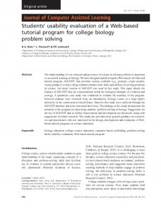
For this reason the WSPICE project (see Fig. 1) was launched in Spring 2002. WSPICE is still in the stage of development. The current version is freely accessible for everyone via the Internet.
Figure 1 WSPICE simulation environment: Snapshot of the schematic editor and simulation results.
2 WSPICE Architecture WSPICE is a client-server application as shown in Figure 2: On the client side, a schematic editor, called WSchematics, is used for circuit entry and SPICE netlist generation. The server side basically consists of a Perl-Script that manages the entire data flow between the SPICE simulation engine2, the SPICE Output Interpreter (SOI) and a plotting program (Gnuplot), which is used for graphical postprocessing of the simulation results.
2
OrCAD PSpice version 9.1 Eval
2
In order to make WSPICE applicable even for low-bandwidth internet connections (modem), network traffic considerations played a decisive role during the development phase of the project. This led to the described client-server architecture. In order to minimize network traffic, only the schematic editor (size: 180 kByte) is sent to the client. Because of its size (2.5 MByte), the SPICE simulator remains on the server. Starting the simulation will cause WSchematics to generate a SPICE netlist of the current circuit (approx. 1 ... 10 kByte) and send it to the server. On the server, the Perl-Script starts a SPICE simulation based on that netlist. After the simulation has finished, the simulation results are loaded into the SPICE Output Interpreter (SOI), which is also written in Perl. The SOI analyses and reformats the data for the further processing steps. The public domain plotting program Gnuplot is used to convert the data into portable network graphics format (png). Thereafter, the images are embedded into a dynamically created HTML-document which will be sent back to the client. The emerging network traffic of this method is negligible, because one image is only 4 kByte in size.
Client
Server
Network
WSchematics Netlist
Netlist
SPICE Engine Output
SPICE Output Interpreter
PerlScript Simulation-Results
Data
HTML + Graphics
Gnuplot Graphics
Figure 2 WSPICE architecture and data flow.
WSchematics, the schematic editor, is implemented as a Java applet in order to make it platform-independent, small in size and capable for integration into interactive courseware. To ensure the maximum possible compatibility and independence of additional software and plugins, only the standard AWT (Abstract Window Toolkit) components of the Java Development Kit [8] have been utilised. The handling of WSchematics is based on the wellknown commercial program PSpice Schematics [9], but on some points, WSchematics has been optimized with regard to its use in education (see next section).
3
3 Working with WSPICE - an example 3.1
Starting the simulation
A demonstration of the WSPICE capabilitiy for integration into interactive courseware can be found at the following URL [10]: http://smile.unibw-hamburg.de/WebSpice/DemoLehrtext.html (see Fig. 3). After loading the document, one can start working, as soon as the applet status field on the top of the course document indicates, that the download process of the WSchematics applet has successfully finished. The presented example covers the subject "Die Emitterschaltung" (=Common Emitter circuit) and it consists of text sections and images showing appropriate electronic circuits. Clicking on the image labeled as "Abb. 1" will cause WSchematics to start and automatically load the shown circuit (see Fig. 4). One benefit of WSPICE - especially for educational purposes - is, that this circuit can now be arbitrarily edited, simulated and thus intensely studied. Clicking the 'Start Simulation'-button will cause WSchematics to perform an electical rule check (ERC) and, if no errors occur, create a netlist of the circuit and send it to the WSPICE-server. After the simulation has finished, the simulation results are shown in a separate browser window, whereas the bias voltages of all circuit nodes are displayed directly within the schematic (see Fig. 1).
Figure 3 WSPICE demonstration course document
4
Figure 4 Clicking on an image of the demonstration course document will cause WSchematics to start and automatically load the shown circuit
3.2
Editing circuits
The comfortable GUI (graphical user interface) of WSchematics allows the user to easily draw, edit and simulate electronic circuits. Electronic parts can be placed, moved, edited and connected using wires and ports. All major types of SPICE analysis, like DC Sweep-, AC Sweep- (frequency response), Transient-, and Fourier-analysis, are supported. Voltage- and current markers are used to indicate, which simulation results are to be displayed. WSchematics is equipped with a clipboard functionality (cut, copy & paste) as well as with several zoom-functions. Circuits can be saved and opened, if the user allows the applet to access the local harddisk. Furthermore, PSpice Schematics files can be imported. In most of the dialog-fields, user entries have to pass through a strict format check. In the case of invalid entries, informative error messages are displayed in order to help the user to locate and fix the erroneous inputs. The "Get new Part"-dialog shown in Figure 5 is used to place new electronic parts on the schematic. In this example, a 1kΩ-resistor, temporarily labeled as "R?", has been placed close to the bipolar transistor Q1. The "Get new Part"-dialog lists all parts that are contained in the WSPICE library, inclusive a short and helpful description. A search function for parts is also available.
5
Figure 6 shows an example of the "Edit Attributes"-dialog, which is used to edit part parameters. If the current part is a stimulus (= time-dependent source), its waveform can be displayed by clicking the "Preview"-button. This allows the user to easily adjust stimulusparameters in order to get the desired waveform. In this example, the sine-source Vin is edited. The modification of the parameters TD (delay time) and DF (damping factor) led to the shown sinusoidal waveform.
Figure 5 Placing new parts using the "Get new Part"-dialog
Figure 6 Editing part parameters using the "Edit Attributes"-dialog 6
3.3
Setting up the simulation
The "DC Sweep"-dialog shown in Figure 7 is used to set up the DC Sweep analysis. In this example, the DC voltage at node "out" is to be calculated, depending on the load resistance RL. For this reason, a voltage marker has been placed at the appropriate node and the "Part Attribute"-radio button in the "DC Sweep"-dialog has been selected. This is a suitable demonstration for the intelligent dialog elements that are used by WSchematics: The "Part Type"-input field only lists those part types that are used in the circuit and which have variable numeric attributes, in this case "R" (resistors) and "V" (voltage sources). After having chosen "R" as the desired part type, the "Part Name"-input field lists the names of all resistors used in the schematic (here: "RC" and "RL"). It is obvious, that this method prevents from invalid user entries and thus simplifies operation. At last, the user has to select the Sweep Type (e.g. "Decade") and to enter the start- and end-values as well as the number of points per decade. 3.4
Getting help
WSchematics is equipped with a Quick Start Tutorial, which is a hands-on learning tool for new users and for users who wish to refresh their knowledge of the program. The tutorial demonstrates the basic tasks for circuit-simulation, namely "schematic entry" and "analysis setup". Moreover, a Quick-Help-function for all part attributes and model parameters is available. In Figure 7, the part type "R" has been chosen. Thus, the appropriate help text "Resistance (in Ohms)" is displayed in the help-field at the bottom of the WSchematics main window.
Figure 7 Setting up the DC Sweep analysis
7
4 Conclusion WSPICE is a web-based and platform-independent circuit-simulation environment, equipped with an comfortable graphical schematic editor. The simple and intuitive usage as well as the capabilitiy for integration into interactive courseware make it a useful tool, especially for educational purposes. For the future, a graphical and more flexible waveform viewer will be implemented as well as the support of digital devices and hierarchical designs (subcircuits). Because of the restrictions of the currently used simulation engine (OrCAD PSpice Eval), it is planned to switch to an unrestricted and public-domain simulator like Berkeley Spice2 or Spice3.
References: [1] Homepage of the Institute of Electronics, University of Federal Armed Forces, Hamburg, Germany. http://www-elo.hsu-hh.de [2] S.m.i.L.E Homepage. http://smile.hsu-hh.de [3] Souder, D.; Herrington, M.; Garg, R.; DeRyke, D.: JSPICE: A Component-based Distributed Java Front-End for SPICE. [4] Wilamowski, B.; Malinowski, A.; Regnier, J.: SPICE based Circuit Analysis using Web Pages [5] AEi Systems, webSPICE-Homepage: http://www.aeng.com/webspice.asp [6] Institute of Electronics, University of Hagen, Germany: SPICE simulations: http://www-es.fernunihagen.de/playground/SPICEindex.html.en [7] Center for Electronic Systems Design, University of California at Berkeley: The SPICE page: http://bwrc.eecs.berkeley.edu/Classes/IcBook/SPICE/ [8] Sun Java Technology: http://java.sun.com/ [9] OrCAD PCB design solutions page: http://www.orcad.com/ [10] WSPICE demonstration course document: http://smile.unibw-hamburg.de/WebSpice/DemoLehrtext.html
Authors: Holger, Goebel, Univ.-Prof. Dr.-Ing. Henning, Siemund, Dipl.-Ing. (FH) University of Federal Armed Forces Institute of Electronics, FB ET Holstenhofweg 85 D-22043 Hamburg
[email protected]
8