WWW-based 3D Distributed Collaborative Environment for Telecommunication Network Management Mohsen Kahani, H. W. Peter Beadle Department of Electrical and Computer Engineering, University of Wollongong Northfield Avenue, Wollongong, NSW 2522, Australia Phone: +61-42-21-3065, FAX: +61-42-21-3236 E-mail:
[email protected],
[email protected]
Abstract ATM technology simplifies the application of logical connectivity and Virtual Private Network (VPN), which provide more flexibility for network management. This flexibility increases the complexity of management task, and requires special treatment. In this paper, we introduce a WWW-based threedimensional user interface, in which managers can collaborate with each other to efficiently manage distributed heterogeneous networks.
ATM Device
Corp. X’s NMS
1. INTRODUCTION It is believed that the management of emerging networks requires greater visualisibility and interactivity than that provided by traditional user interfaces [1, 2]. The manager in these environments has to deal with tens of thousands of virtual channels, and potentially hundreds of ATM switches [3].
Carrier’s NMS
Corp. Y’s Site m
Public ATM Network
Private ATM Network Corp. X’s Site 1
Corp. X’s VPN
Private ATM Network
ATM Device
Corp. X’s Site 2
Corp. X’s VPN
Corp. X’s Site n Private ATM Network
Corp. Y’s Site 1
Corp. Y’s NMS
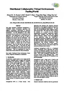
Figure 1- An example of virtual private networks
2. WORLD WIDE WEB (WWW) In this paper, we discuss a three-dimensional collaborative environment for distributed management of telecommunication networks. We focus on issues related to virtual private networks (VPNs) overlayed on an ATM core network (Figure 1). The user interface is based on a World Wide Web (WWW) browser using both text (HTML) and 3D graphics (VRML). This means that the interface is cheap, highly available and platform-independent. Firstly, we provide some background information on WWW technologies and protocols. In particular, we briefly discuss HyperText Markup Language (HTML) and Virtual Reality Modeling Language (VRML). Then, the special requirements of a distributed user interface for network management are discussed, followed by the explanation of the architecture of the proposed system. Finally, Some of the most important implementation issues, observations, and conclusion are presented.
Internet has grown dramatically in recent years, and has become the main tool for interconnecting computers and systems. The emergence of World Wide Web (WWW) and hypertext technology has transformed the Internet from mostly text-based email messages and bulk file transfer into multimedia applications consisting of video and voice parts. WWW uses HyperText Transfer Protocol (HTTP), layered on top of TCP/IP, to transfer HyperText Markup Language (HTML) documents between computers. An HTML document consists of a set of anchors and links that relate it to other documents. Although the evolution of HTML is a major breakthrough, it is still based on text and a set of two dimensional images and voice clips. To further enhance it, and allow the use of three dimensional graphics, Virtual Reality Modeling Language (VRML) was developed. VRML has been designed to be a “universal description language for multiparticipant simulation” and to meet the following requirements: platform independency, extensibility,
and the ability to work well over low-bandwidth connections [4]. VRML version 1.0 does not support interactive behaviours. That is, the world is static and the user only can navigate into it. Version 2.0 [5], on the other hand, supports object’s behaviour, and allows nodes to have input and output parameters. It also provides linking with external APIs and can be linked to languages such as C++ or Java. The Java language is a class-based object-oriented programming language, and is designed to be machine-independent and platform-independent [6]. Java can be used in two methods: standalone program or applet. Standalone programs run on a computer using Java interpreter. Java applets are used by web-browsers and are combined with HTML or VRML files to enhance their capabilities. Using Java and VRML, it is possible to build a distributed multi-user three-dimensional environment in which a user can see the representative symbols of other participants, and collaborate with them in a virtual environment. We will use this environment to build a network management system, and show how it can be used to effectively manage more complex networks.
3.
SYSTEM REQUIREMENT
The system that we propose here is a distributed virtual reality (DVR) system. DVR systems are mostly used for simulations, such as SIMNET [7], or computer games. However, in a network management environment, there are several issues that have to be treated differently. These issues are: - Bandwidth. The amount of bandwidth used by a network management system should be as small as possible, compared to actual network traffic. Network management tasks (eg. device polling) consume a considerable amount of bandwidth by themselves, so the system should be designed so that the distributed VR user interface does not add much more traffic. Unlike some other systems in which the distributed system, itself, is the goal (eg. games or simulators), the total amount of bandwidth consumed by network management system (device polling and operators' collaborations) is considered waste, and reduces the network throughput. - Reliability. Reliability is a major issue in network management. In a distributed VR game if some update messages are lost, the effect on the overall system is not dramatic. In a network management environment, each individual message may carry important information, and may have catastrophic
effects on the network, if does not reach the destination. To fulfil both reliability and bandwidth restriction conditions, we recommend the utilisation of a reliable end-to-end protocol, such as TCP/IP, instead of a best effort communication protocol. The connection is continuously monitored, and in case the it is broken due to network failure, the connection will be re-established.. - Number of Users. Most distributed simulators have a large number of participants, spreaded over several LAN segments. As a result, the communication of update messages among users is done via either broadcasting or multicasting. In a network management environment, however, the number of participants is relatively small, and it is less likely that two or more users join the system from the same LAN. As a result, a point-to-point unicast communication model should be used. - Security. For most distributed simulation systems, security is not an issue. Some of those systems have a dedicated network, which physically maintains the security, for others, such as distributed games, the data is not sensitive. None of these are true for a network management environment. As a result, special security measures have to be considered.
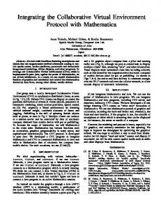
4. SYSTEM ARCHITECTURE The system uses a client/server architecture based on the Telecommunication Management Network (TMN) model [8]. Each server host communicates with a network management system and uses its services to get the management information. This information is sent to the clients, which are WWW browsers enhanced with VRML, Java and JavaScript. Each VRML object can have a link to other views that may be within the domain of another network management system (NMS). This allows an integrated view of distributed networks in which each subnet is managed by an independent NMS. Moreover, managers can collaborate with each other, in real-time, to solve the problems that involve more than one domain. Figure 2 illustrates this architecture. Each server consists of four parts: NMS interface, Collaborative Manager (CM), an object-oriented database (OODB), and an HTTP server, as shown in Figure 3. The NMS interface communicates with the network management system via its command line interface (CLI). The NMS can be any system capable of gathering information from network elements (NEs), and in our case is Cabeltron Spectrum. The interface queries the NMS to get management information about the status of NEs, and stores them
in the OODB. It also gets update information from the database and sends it to the NMS.
NMS n
NMS 1 NMS 2
S erv er 1
S e rv er 2
S erv er n
is to separate the NMS specific part of the server from the CM part, which is NMS-independent. It also makes the implementation easier, more modular, and more maintainable. As the system is used in heterogeneous environments with different types of NMS, the only part that varies is the NMS-interface. The object oriented database is based on ODE[9], and uses facilities such as events and triggers that allow effective change verification and notification.
NMS Interfac C lien t 1
C lien t 2
HTTP Server
C lien t m
Figure 2- System architecture The collaborative manager (CM) is the core of the system. It communicates with the clients directly, or via HTTP server, through a Common Gateway Interface (CGI) script. It also coordinates the collaboration between clients, by collecting the update information from each client, multicasting them to the other clients, and storing it in the OODB. The scenario is as follows: The manager uses an enhanced WWW browser to connect to the HTTP server. After authentication, the HTTP server asks from the appropriate view from the CM via CGI protocol. The CM responds with a set of documents in HTML and VRML formats. These documents contain Java code that firstly, establish a TCP/IP connection between the client and the server, and secondly, control the behaviour of NEs in the client’s environment. The user can then navigate into the 3D virtual world, interact with NEs and manipulate the world scene. The position of the navigator and its manipulation's data are continually sent to the CM via the established connection. The Java applet also listens to the connection and updates the world scene based on the receiving data. Whenever the CM receives update data from any client, it broadcast the data to all the other clients and updates the database. If the change has to be notified to the NMS, it set a flag in the database indicating that NMS interface has to send it to the NMS. In case the user requires more information from the NMS, the request also is recorded in the database. The NMS interface then sends the request to the NMS, and after receiving the required data, puts it in the database. The CM, finally sends the result back to the requesting client. The whole scenario is illustrated in Figure 3. All communication between CM and NMS-interface is through the object-oriented database. The rationale
Network Management System (NMS)
CLI
OODB
Server
CGI
Collaborative Manager(CM
HTTP Enhanced WWW Browser
Clients
Figure 3-Details of client/server communication
5. IMPLEMENTATION There are several issues related to this implementation that we will elaborate more in this section.
Server The server consists of several parts communicating together via an object-oriented database. HTTP server, collaboration manager, all the CGI scripts and NMS interface are working in a Unix-based operating system. CGI scripts are written in C++ language to be able to use the services of object oriented database.
Client There are plenty of WWW browsers available for most platforms, including Unix, PC and Macintosh. As the client software is platform-independent, it allows the manager to connect to the system from virtually any computer in the network. However, security measurement may restrict connection to a specific group of workstations. Modern browser allow the division of client’s window into several frames. We have used this feature to have both text (HTML-based) and graphics (VRML-based) frames at the same time. The network structure is shown three-dimensionally in graphics frame, and textual information is displayed in the other frame. Textual information includes some general information about current view, as well as special data requested by the user, such as MIB variables view.
Client/Server communication The client and server communicate via the HTTP protocol and through an established connection. Initial requests and textual information are retrieved via HTTP protocol by communicating with the HTTP server. Update information is sent through the established connection. We use a modified version of Distributed Interactive Simulation (DIS) [10] protocol for update notification. This protocol utilises ‘Dead Reckoning’ technique to reduce the rate of data exchange. In dead reckoning method, instead of continuously sending the absolute position of objects, the location, the velocity vector and a timestamp is sent for each object. Data is only resent when the velocity vector changes. The receiver uses the data to calculate the location of the object at any intermediate time.
Configuration management We use 3D objects to represent NEs in the virtual world. The name of each object appears below the object symbol. The name is also a link to more textual information about the object, which will appear on the text frame whenever it is clicked. The symbols of some objects, such as connections, act as links to more detailed view of those objects. For instance, clicking on a link, might show the VPCs and VCCs that are passing through the link. Some objects, such as routers and gateways, appear in several views. So their 3D symbols are links to the other views. That is, by clicking on the object’s symbol, the main view of the object is displayed. This may require the connection to another NMS, which is transparent to the user except when authentication is required. For instance, suppose that a domain has a router that connects it to another domain. By clicking on the router’s representation, the manager can eventually connect to the other domain, which is being serviced by another NMS. This may require authentication from the other NMS, and may result in refusal, or partial view of that domain. This can be seen as an implementation of the X interface in TMN architecture. As the client connects to the system from different platforms with different graphics and processing powers, it is desirable that the complexity of graphics be different for each computer. This means that a powerful machine can have a more realistic view with textures and smooth shading, while a less powerful computer can view objects as simple primitive geometric shapes. This facility is provided by letting each client have local copies of the symbols to represent the network elements. This
feature also significantly reduces the traffic required to transfer the object symbols to the clients.
Fault management Fault information, such as link failure or device breakdown, is shown via colour coding, blinking symbols or using different symbols. For example, a link failure can be represented by a broken line, and a faulty device can blink to attract the manager’s attention. Some browsers also allow the use of directional sound, which can be used for alarm reporting.
Performance management Some types of performance data can be directly represented by the system as part of the virtual world. The thickness of links can represent the amount of load and their colour can show the status of the link. Using the text frame, it is also possible to show the performance charts by using graphical features of Java. It is also possible to link the system to more sophisticated software, such as spreadsheets, to present the performance data in different manners.
Security management Although, this system does not involve in security management of the network, it has some security issues that has to be addressed. That is, as anybody with a browser can potentially connect to the system, some restrictions should be applied to it. Two kinds of security have been considered for the system: IP address restriction and User IDs. Only browsers from privileged IP addresses can connect to the system, and each user has a unique user ID and password. IP addresses are checked for all transactions, but the user IDs are only checked at connection establishment time. Also, Users have different access privileges; some have read/write access, while others only have read privilege. It is also possible to use firewalls to exclude the intruders from the outside of the domain to have access to the system. Other security measurement, such as content coding for update data, can also be considered based on the importance of management information.
6. OBSERVATIONS The implementation of the system is not complete yet. Here we present some initial observations and results from the prototype system. The main feature of the implementation is its platform-independency. The manager can connect to the network, from any computer at any point, either remotely or locally,
from his/her notebook or a Unix workstation, and uses full capabilities of the system. The managers can take mobile computers with themselves to the fault locations, and collaborate with the managers at the central station to fix the fault quickly, and with greater confidence. The three-dimensional view of the network hierarchy and additional navigational facilities increase the visualisability of the network management information. The greater visualisibility means the lower probability of error and miscalculation of the manager, which directly increases the network survivability and reduces down time. The user connects to the system by pointing her browser to a specific URL address. After authentication process, she receives a combination of text and graphics in a framed window, as shown in Figure 4. The graphical window shows the structure of the network in a three-dimensional environment. Network elements are represented by 3D objects. These symbols are chosen so that they can be recognised by the user as true-representations of their real counterparts. Each object can have two kinds of links: graphical and textual. Objects that act as links between different views have a graphical link (shown as small spheres in Figure 4). By clicking on the link, another graphical view is presented. So, the user can navigate the whole network by clicking on link-objects within each view. All objects have a textual link. The link is presented by a text line under the object showing the object’s name (As the current beta version of VRML plugin
doesn’t support text, these links are represented by rectangular boxes). By clicking on this link, textual information are presented in the text frame. The text frame shows some useful information about different sections of the network. After requesting a new view, some general information about that view, including number of network elements and number of managers are shown. Several buttons are also provided, so that the manager can view the alarms and events related to the current view. By clicking on the text link of an object, initially general information about the object are shown in the text frame. Manager then can click on appropriate buttons to see the details of alarms and events associated with this object. She also can ask for partial and complete Management Information Base (MIB) variables view. For the moment, only a textual communication between managers has been provided. Using this facility, managers can talk to each other, and solve the problem collaboratively. We plan to examine other kinds of communication including telephonelike conversation. The impression of people seeing the system is that, despite its preliminary implementation, its 3D view and mixture of text and graphics gives the manger more flexibility than available two-dimensional commercial network management systems. Incorporating voice communication between participants and using more realistic and complex scenes will improve further the system’s efficiency. Compared to other commercial network management systems, this system is cheap. With plenty of WWW
Figure 4- A typical view of the system
browser available for free or very cheap, the manager can use their current computers to connect to the system without any extra cost.
7. CONCLUSION
(TITR) of University of Wollongong is also hereby acknowledged.
REFERENCES
[1] Crutcher, L; Lazar, A; Feiner, S; Zhou, M, "Management of Broadband Networks using a We have been constructing a WWW-based three3D Virtual World", 2nd Intl. Symp.on High Perf. dimensional interface in which operators can Distributed. Computing, 1993, pp. 306-15. effectively manage distributed heterogeneous broadband networks, collaboratively. The system[2] Kahani, M., Beadle, P., “Using Virtual Reality to Manage Broadband Telecommunication uses client/server approach to implement a TMNNetworks”, ATNAC’95 Conference Proceeding, style network management system. The server part Vol. 2, 1995, pp. 517-522 uses an object-oriented database to exchange information between participants and the network[3] Alexander, P., Carpenter, K., “ATM Net management system. The client, is a cheap WWW Management: A Status report”, Data Combrowser enhanced with VRML and Java capabilities. munication Magazine, September 1995. The prototype system depicts some useful features. [4] Bell, G., Parisi, A., Pesce, M., “The VRML 1.0 Most commercial management systems use graphical Specification”, May 1995. workstations which are relatively expensive. The communication with the system using other platform[5] Bell, G., Marrin, C., et al., “The VRML 2.0 Specification”, 4 August 1996. is only through text-based command line interface, which is not useful for complex networks. On the[6] “Java Language Specification: version 1.0”, Sun other hand, in our implementation, the managers can Microsystem, 1996. connect to the system, and do full network operations from any location in the network using virtually any[7] Pope,A., “BBN Report NO. 7102, The SIMNET Network and protocols”, Technical .report, BBN computer. A more powerful computer can deliver a systems and Tech., Cambridge, MA, July 1989. very realistic view featuring texture mapping and smooth shading, while in less powerful machines a[8] ITU-T Recommendation M.3010, “Principle and rather primitive view, with a reasonable speed, can Architecture for the TMN”, Geneva, 1992. be shown. [9] Arlein, R., Gava, J., Gehani, N., Lieuwen, D., The three-dimensional and collaborative environ“Ode 4.2 (Ode) User Manual”, AT&T ment created by this system, firstly, provides greater Bell Laboratories, April 1996. visualisation of the system, and secondly, allow realtime communication between managers, which is[10] ANSI/IEEE Std 1278-1993, “Standard for Information Technology, Protocols for Distribnecessary for management of complicated and uted Interactive Simulation”, March 1993. flexible broadband networks based on ATM technology. The other advantage of the system is its short learning time. For most commercial systems, the operator training is a real problem. As nowadays most of people are reasonably familiar with WWW browsers, no training on the use of user interface is required. So the training can only focus on the issues related to network management. Finally, Although we used this system for network management purposes, the generic structure can be used in any application that require data visualisation and collaboration.
ACKNOWLEDGMENTS This work is supported by a postgraduate scholarship from ministry of culture and higher education of I.R. Iran granted to M. Kahani. The financial support of The Institute for Telecommunication Research