Xflow – Declarative Data Processing for the Web Felix Klein∗ Saarland University Intel VCI
Kristian Sons† Saarland University Intel VCI DFKI Stefan John¶ Universit¨at Braunschweig
Dmitri Rubinstein‡ Saarland University DFKI
Sergiy Byelozyorov§ Saarland University IMPRS-CS
Philipp Slusallekk Saarland University Intel VCI DFKI
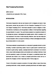
Figure 1: 3 example applications with Xflow. Each screen shot shows a web page that uses XML3D and Xflow to render real-time 3D graphics with advanced data processing. The left picture uses multiple instances of mesh interpolation for animation. The middle picture shows a dynamically generated noise texture. The right screen demonstrates multiple instances of skeletal animations.
Abstract
Graphics and Realism—Animation; I.3.6 [Computer Graphics]: Methodology and Techniques—Languages
The Web evolved from a simple information medium to an interactive application platform featuring advanced 2D layouts, videos, and audio. At the same time, support for hardware-accelerated 3D graphics improves continuously even among mobile devices. Hence, there is a renewed interest in adding interactive 3D graphics to the overall Web experience and therefore a need for highperformance data processing beyond DOM modifications through JavaScript. A challenge in adding this functionality to Web technologies is to close the deep gap between low-level hardware programming (e.g. using WebGL or WebCL) and high-level Web development with HTML, CSS and JavaScript.
Keywords: XML3D, dataflow, visualization, Web3D, WebGL
1
It is not just with the arrival of HTML5 that the Web evolved from a pure information medium to a full-fledged application platform. HTML is no longer the least common denominator that works the same on every platform: Browser vendors’ competition moved from browser gadgets to breadth and speed of support for emerging Web standards. The continuing migration of desktop applications to cloud based and hybrid web applications will lead to browser platforms that have to expose the hardware performance optimally.
In this paper we present Xflow, a system for declarative, highperformance data processing. In combination with XML3D, it allows Web developers to combine a 3D scene graph with dataflows. Our approach is general enough to allow meshes, shaders, texture samplers and the canvas itself as sink of these dataflows. Thus it enables data processing e.g. for dynamic meshes, animation of shader parameters, image processing and post processing. In this first stage, we define a set of generic building blocks that can be used to construct more complex operations. This gives a large degree of flexibility, but is still abstract enough to increase ease-of-use and ensure security. To maximize performance, dataflows are automatically connected to the render pipeline and mapped to both CPU and GPU, thus harnessing parallelization. In order to evaluate our system, we have created a number of examples.
This development is expressed in the emergence of new programming and execution models such as Web Workers, River Trail and WebCL. These approaches expose available hardware functionality to the Web developers in an imperative way. They will be discussed in Section 2.1. Interactive 3D graphics requires a lot of data processing. Well known use cases are skinning and morphing for the animation of organic objects, spring-mass systems for the simulation of cloth,
CR Categories: I.3.7 [Computer Graphics]: Three-Dimensional ∗ e-mail: † e-mail: ‡ e-mail: § e-mail: ¶ e-mail: k e-mail:
Introduction
Copyright © 2012 by the Association for Computing Machinery, Inc. Permission to make digital or hard copies of part or all of this work for personal or classroom use is granted without fee provided that copies are not made or distributed for commercial advantage and that copies bear this notice and the full citation on the first page. Copyrights for components of this work owned by others than ACM must be honored. Abstracting with credit is permitted. To copy otherwise, to republish, to post on servers, or to redistribute to lists, requires prior specific permission and/or a fee. Request permissions from Permissions Dept, ACM Inc., fax +1 (212) 869-0481 or e-mail
[email protected]. Web3D 2012, Los Angeles, CA, August 4 – 5, 2012. © 2012 ACM 978-1-4503-1432-9/12/0008 $15.00
[email protected] [email protected] [email protected] [email protected] [email protected] [email protected]
37
particles for effects such as smoke and fire but also post processing and image processing in general. These use cases require to run computation on large arrays of uniform data on a frame by frame basis. For 3D graphics in the browser’s DOM [Behr et al. 2009; Sons et al. 2010], recalculation of the data via JavaScript is too slow (c.f. Section 7). Thus, we were looking for an approach that is suitable for most of the use cases, can expose the hardware capabilities optimally, and is still easily usable for Web developers.
means that security issues need to be solved. The security issues are even more critical compared to WebGL, because OpenCL has very direct access to memory e.g. through pointers. The three imperative approaches expose multi-core e.g. multiparallel hardware capabilities on different abstraction levels to the Web author. They are not directly comparable to declarative approaches such as Xflow and both can exist next to each other. One could say, Xflow is to XML3D what WebCL is to WebGL. Apart from that, we can use these techniques to implement a JavaScript prototype of Xflow.
With Xflow we present a new declarative approach to data processing. Actually Xflow is applicable to all domains that require processing of large data sets in the DOM. In this paper we limit ourselves to the usage of Xflow in the context of XML3D. Though XML3D as presented in [Sons et al. 2010] did not include dynamic meshes, this feature was planned from the beginning and has finally been integrated in version 0.4. The new design not only allows the definition of dataflows for data processing. It allows to compose data structures in a granular and easy to understand way with the possibility to reference data from external resources. This new data structure maps optimally to modern graphics API features such as the OpenGL Vertex Array Objects.
2
2.2
Dataflow is a term in computing, that is used for hardware architectures (e.g. [Dennis and Misunas 1975; Khailany et al. 2001]). Derived from these architectures, dataflow programming describes a program as a network of operators that forward data to each other, where each operator is run once all of its input data from other operators is available. This paradigm fits well for modern multi- and many-core hardware offering various options for thread- and datalevel parallelism. Dataflow software architectures can be found in various domains, in particular for multimedia processing [Black et al. 2002; Microsoft 2012].
Related Work
In this section we discuss recent approaches to expose hardware capabilities to web developers in an imperative way. Then we discuss classical dataflow systems and the combination of scene graphs with a dataflow. We show related approaches in COLLADA and X3D and finally a dataflow approach for 2D image processing in SVG.
2.1
Dataflows
2.2.1
Dataflows in Scientific Visualization
The combination of dataflow algorithms with computer graphics has a long history. The central architecture of systems such as AVS [Upson et al. 1989], Data Explorer [Lucas et al. 1992], and VTK [Schroeder et al. 1996] are build around user configurable dataflows networks, often editable via some user interface. These visualization systems are typically designed to work with a large amount of input data from a discrete simulation or from sensor data. After a filtering step, in which the data is e.g. converted and sampled, there is a mapping to a graphical representation, which is finally presented to the user. The steps before the rendering can require computation time due to the large amount of input data. Visualization is usually an iterative process, e.g. changing the time step in the input data often triggers recalculation of the whole graph.
Imperative Approaches for the Web
JavaScript has originally not been designed to express parallel execution programming. Recently a series of projects emerged, that aim to tackle this limitation. The draft specification Web Workers [World Wide Web Consortium 2012] defines an API that allows running scripts in the background independently of any user interface scripts. Web application authors can launch a Worker thread that runs in a separate parallel execution environment and communicates with the main thread via message passing. This API exposes multi-threading capabilities of the hardware. The specification emphasizes that Workers have a high start-up performance cost, and a high per-instance memory cost and thus should only be used for larger calculations.
The input data of a graph node is often an abstract type and the algorithm is branched inside the node depending on the actual data. This makes it very difficult to globally optimize the data flow and to merge operations. Thus the classical system typically leverage hardware acceleration only locally on a node by node basis. Though there are approaches to control the workflow and show the results of the dataflow in the web browser [Jomier et al. 2011; Niebling et al. 2010], the scientific visualization systems are not designed to perform dataflow calculations on the client-side in the browser. Also, the objective of Xflow is different: Xflow is designed for real-time processing. Many processing steps will be executed on a frame by frame basis.
The Intel project River Trail [Herhut et al. 2012] extends JavaScript by simple data-parallel constructs to expose multi-core capabilities as well as SIMD instructions to the Web author. The central data structure is the ParallelArray. It takes an array-like object, e.g. a JavaScript Array or Typed Array, as input data and provides methods such as map or reduce. These methods take a function as parameter. This function gets executed on the arrays in parallel. The aim of River Trail is to reach a low start-up performance cost such that it is worth to use the parallel data structures even for smaller computations. Since the functionality of the ParallelArray is clearly defined, the hardware capabilities can be exposed in a safe way.
Having said that, there are also many similarities and we consider lightweight scientific visualization for the Web as one important use case for Xflow. 2.2.2
WebCL [Khronos Group 2012] is a JavaScript binding to OpenCL defined by the Khronos group. OpenCL [Khronos Group 2011] is a language and low-level-API to harness GPU and multi-core CPU parallel processing. Providing this functionality through a JavaScript API comes with all the pros and cons known from WebGL: WebCL is a low-level API with a high entry barrier for Web application authors. It exposes the hardware capabilities very directly, thus it can be very efficient and flexible. But this also
Dataflow in Open Inventor
CashFlow [Kalkusch and Schmalstieg 2006] is a dataflow extension to the OpenInventor [Strauss and Carey 1992]-compatible scene graph framework. CashFlow, in contrast to Xflow, uses OpenInventor traversal concepts instead of direct connections between processing and visualization nodes. It stores processed data in the traversal state, making the dataflow order a side-effect of a traversal order used to render a scene. Nodes that manipulate traversal state
38
influence the rendering result. For example separator nodes keep changes of the processed data local to all children of a separator. Without a separator, changes are applied to all nodes visited in the traversal order after the data are changed. This makes the job of a scene author difficult as he needs to carefully place dataflow nodes into the scene, so when visited by a scene graph traversal they produce desired effect. With Xflow, the author designs the dataflow by connecting dataflow nodes, and Xflow takes care that they are processed in a correct way.
2.3
scene graphs as part of the web page. As a declarative approach, it fully leverages other Web Technologies, such as the Document Object Model (DOM) and Cascading Style Sheets (CSS). As a result, an interactive 3D scene graph can be developed just like any other Web application, enabling thousands of Web developers to work with 3D content with minimal learning effort. In this section, we shortly review the previous XML3D specification [Sons et al. 2010] with respect to performance, highlighting advantages as well as limitations, which we address with Xflow.
COLLADA
3.1
COLLADA [Khronos Group 2008] is a 3D data format to exchange assets among digital content creation (DCC) tools. The major design principle was to reduce the loss of information between those DCC applications. Consequently it does not consider requirements on an interactive real-time format, defines no interaction and no runtime behavior. Nevertheless, COLLADA can be found as input format for many WebGL libraries, since it’s one of the few open graphics formats to include animation, skinning, and morphing information.
XML3D featured a generic declaration of data buffers, which are optimized for modern graphics hardware and do not require any conversion. This declaration was based on a number of Input elements for different data types. Supported types were the basic types ,, , the vector types , , , , the matrix types , as well as . Input elements of basic, vector, and matrix types could define an arbitrary number of values, declared in the node’s value. The element could include an HTML
tag (and potentially other HTML elements like
) to define a texture of flexible size and format.
COLLADA defines a dataflow model to provide a generic way to connect data sources with sink elements. However, it’s not possible to create deep flow structures and is the only element that defines an operation on data sources.
2.4
Input elements could be connected to different nodes, including for geometry and for surface shading, via the element. Each bind elements used the semantic attribute to correctly assign the data buffer to the sink. (e.g. expects data buffers with semantics index and position)
X3D
X3D is an ISO standard [Web3D Consortium 2011] file format to represent interactive 3D scenes. It features a dataflow mechanism to describe all dynamic aspects of the scene by connecting individual node fields via ROUTEs. By integrating sensor, interpolation, and visualization nodes into the dataflow it is possible to describe animated scenes without any scripting. Additionally this dataflow allows the construction of cycles in the dataflow and supports animation of geometry via special nodes (e.g. CoordinateInterpolator, Humanoid Animations), as well as the integration of script nodes into the dataflow.
Since the declaration of the geometry requires a lot of memory, instantiation is an essential feature for any 3D scene graph. XML3D allowed for reuse of a declared elements with the element, which referred the mesh by document id.
3.2
SVG Filter Effects
Scalable Vector Graphics (SVG) [W3C 2009] is an XML-based file format for two-dimensional vector graphics. It features Filter Effects for simple 2D image processing that are applied as a post-processing step on the rendered vector graphics. Filter Effects are declared as a dataflow based on a connection of fixed-function operators. These operators include effects like blurring, specular lighting, color compositing, blending, and so on. Filter effects are declared independent of the input graphic and can be assigned to SVG graphic and container elements via attributes and CSS properties. Thus, they help to maintain the original semantics structure of the SVG document by separating detailed visual properties from the content.
Another problem was flexible instantiation. While geometry could be instantiated as a whole with , it was not possible to reuse individual buffers among meshes (e.g. to have two meshes of the same shape with individual color buffers to change the appearance). The purpose of the element was originally to support the reuse of individual data buffers as well as the connection of processing nodes, using explicit connections via document id. However, during the course of development, we realized that explicit connections via document ids are often impractical if many buffers are involved. Thus, we developed Xflow as a new data compositing and processing system that allows a more compact and practical description of arbitrary data compositions and dataflows.
Even though SVG Filter Effects are limited to simple image processing, they are a good example for a dataflow technology that is well integrated into Web technologies.
3
Limitations
Since the scene graph of XML3D could be accessed and modified via DOM interfaces, it was possible to create dynamic scenes with JavaScript. This was sufficient for simple dynamic effects like rigid body transformations, which only required modifications of the scene graph transformations. However, for more complex animations, one often needs to process mesh data on a vertex level, e.g. for mesh interpolations or skinning. These kind of computations are expensive and would slow down the performance when performed only with JavaScript. Thus, XML3D required functionality to perform these expensive computations efficiently in a dataparallel way.
For a more detailed comparison of X3D and XML3D/Xflow see Section 6.
2.5
Hardware efficient design
Previous XML3D specification
4
As an effort to add declarative and interactive 3D content to the Web, XML3D was developed as an extension to HTML5. The specification adds a minimal set of generic elements to describe 3D
The Xflow System
The goal of Xflow is to provide high-performance data processing capabilities to Web developers. For the design of this technology,
39
we took three important requirements into consideration. int index
Efficiency First of all, Xflow must be designed with efficiency in mind. The execution of the dataflow should be parallelized and integrated with the render pipeline as far as possible. The data layout should allow a simple conversion to hardware buffers with little overhead.
float3 position float3 normal
2 3
baseData float3 position float3 normal float2 texcoord
float2 texcoord
Flexibility Second, the technology must be flexible. Xflow should cover as many use cases as possible and aim to match the flexibility of the programmable graphics pipeline of modern graphics APIs. Usability Last but not least, we must consider usability for Web developers. Thus, Xflow should be well integrated into Web technologies and feature a compact and readable dataflow description. The technology should be stable and easy to use, without the need to deal with hardware related details.
2
1
int index
2
float2 texcoord
3
dataA int index float3 position float3 normal float2 texcoord dataB int index float3 position float3 normal float2 texcoord
0 1 2 ... 1.0 0.04 -0.5 ... 0 1 0 ... 0.0 0.0 ...
With these requirements in mind, we designed Xflow as a declarative language to describe dataflows. Used as an extension to XML3D, it enables Web developers to connect dataflows to the 3D scene graph of the web page. Thus, it allows for leveraging highperformance data processing for interactive, real-time 3D graphics.
10 11 12 ... 1.0 0.5 ..
In this section, we will describe how dataflows are modelled with Xflow and how they are connected with the 3D scene graph. At the end of this section, we will review the design with respect to efficiency, flexibility and usability.
4.1
1
1
Data Compositing Figure 2: An example for data compositing in Xflow. Note that the DataTables of elements ”dataA” and ”dataB” have both their own index field, but share the position and normal field of ”baseData”. Additionally, ”dataB” uses its own texcoord field by simply overriding the field provided by ”baseData”. At the bottom we have two mesh elements that serve as sink for the dataflow to display 3D geometry.
The sources of the dataflow are still declared with Input elements, as described in Section 3.1. However, we no longer use the element to assign Input elements with a semantic. Instead, each Input element is declared with a name attribute to define a named DataField. With the element, Xflow provides a mechanism to combine arbitrary DataFields together. A element may contain any number of Input elements, combining the named DataFields into a named DataTable. Additionally, it may include other elements to merge whole DataTables together. Alternatively, it may refer to another element by document id with the src attribute to reuse its DataTable.
each DataField explicitly (as e.g. necessary in X3D), but can rely on the data composition rules to have a more compact declaration. Additionally, the data composition approach maximizes the reuse of data, since a DataField can be referenced by many DataTables without being copied. This allows us to reuse data on a very fine grained level.
A DataTable has only one DataField per name. Thus, there are a number of replacement rules to deal with equally-named DataFields when combining Input and elements.
Finally, we also support external references by having elements refer to an external document. To do this, we simply write a complete or relative url with id reference (e.g. external/model.xhtml#baseData ) inside the src attribute. This way, we can separate large mesh declarations from the main scene graph, which separates the structure from the main data (similar to in HTML). Note that one external document can contain an arbitrary number of different data sets that can be individually referred using the node’s document id.
1. If the src attribute is used, the named DataTable of the referred element is reused directly, ignoring all child elements. This is the same behavior as defined for nodes in HTML. 2. A DataField of a child Input element always replaces an equally-named DataField of a child element. 3. If the second rule does not apply and two child elements provide equally-named DataFields, the DataField of the latter child replaces the DataField of the former.
4.2
These rules are applied iteratively until the named DataTable includes only one DataField per name. See Figure 2 for an example.
Data Processing
To transform our data composition graph into an actual dataflow, we need to apply operations that process data and generate new output. Thus, Xflow allows us to define a ComputationBlock by attaching operations to elements via the compute attribute. We can specify the type of operation, the DataFields that serve as input, and the name of the output DataFields, which are included in the element’s output DataTable. Note that output DataFields always replace equally-named entries of the original DataTable. See Figure
This data composition mechanism has the advantage that we can easily combine individual DataFields or merge whole DataTables together. Further, it is possible to easily override individual DataFields of a DataTable. In the context of mesh data, we can use this to easily reuse a large set of shared mesh data, while replacing individual fields for each mesh instance. Since we can refer entire DataTables, we do not need to specify a connection for
40
Operators
Input Data
1.0 0.04 -0.5 ... 0.0 1.0 2.0 ... 1.0 0.0 0.0 ... 0.35 0.6
Skinned mesh with normals
Skinned mesh with normals and tangents Skinned mesh with normals, tangents and morph targets
Figure 3: Syntax example for Xflow operators. We attach operators with the compute attribute, specifying the operator (in this case xflow.morph3), the input value assignment inside the brackets (e.g. the DataField position is assigned to input pos) and the name of the output value on the left. This syntax is inspired by JavaScript function calls with the usage of the object notation for argument list.
transform vertex position pose Matrix
mesh with normals
skinning data
transform vertex normals
skinPosition
skinDirection
transform vertex tangents tangents
skinDirection morph vertex positions by weight
morph weight
morph target values
morph3
Figure 4: An abstract example on how Xflow operators can be combined to create dataflows for many use cases. We can nest several ”skinPosition” and ”skinDirection” operators to process an arbitrary number of vertex attributes. Additionally, we can combine different types of mesh animations (e.g. skinning and morph targets) by simply nesting the operators accordingly.
3 for an example of the operator syntax. a sequence as well as a key and returns the linearly interpolated float3 values that matches the key value.
To finally declare a complete dataflow, we connect multiple ComputationBlocks into an graph using a tree of elements combined with references via the ’s src attribute. The execution of the resulting dataflow starts at the leaf nodes and ends at the root, i.e. an operation of a ComputationBlock can only be executed after all child ComputationBlocks have been executed. Note, that the execution order of siblings is independent of each other and can therefore be parallelized. As a first step, we only support undirected acyclic node connections, since those can be effectively optimized and are sufficient for many use cases. We plan to add support for cyclic node connections as a second step (see Section 8).
4.4
On its own, a dataflow declared with Xflow only describes general data processing that can be used for any purpose. To integrate the dataflow into the 3D scene graph, we attach the output to sink elements. In XML3D, we support the attachment of dataflows to the elements for geometry, for surface shading properties and for light source properties. All these sink elements behave exactly like in that they may contain and Input elements as children and can refer another element via src attribute. The result of a sink element, on the other hand, is used exclusively by the 3D scene graph and cannot be further used in the dataflow.
Xflow provides a number of small, generic operators, which can be combined to match the dataflow to many different use cases. Figure 4 demonstrates this for skinning and morph targets. All Xflow operators are designed to operate on large arrays of values. They work without any side-effects on the input data to allow efficient parallelization with shared input. A list of operators can be found under http://www.xml3d.org/xml3d/specification/xflow. Not that this list is only a first version and subject to change.
Sink elements access values from the dataflow via specific names. The element, for instance, always requires at least DataFields of the names ”index” and ”position” to render geometry with vertex array objects. Depending on the surface shader used for the mesh, further DataFields like ”normal”, ”texcoord”, and ”color” are accessed.
While some Xflow operators require explicit array access to the input, the majority of them only defines a simple, element-wise operation. For these operators, Xflow determines the iteration method depending on the input buffer size. Xflow iterates over the minimum range of all input arrays and performs the operation on input values of the same index. However, input values that are scalars are considered uniform input and used for each iteration step instead. With this technique, we avoid the creation of multiple operators, that do the same computation with different iteration methods.
4.3
Connection to the 3D scene graph
The previous XML3D specification included the element to instantiate geometry. However, with the introduction of the element, we can simply reuse one DataTable for two elements, which effectively does the same as instantiating the mesh. In a way, this approach is similar to the way images are ”instantiated” in HTML: many tags refer the same data, which the browser can internally load and allocates only once, reusing it for all instances of the image. The reuse of instead of also resolves issues with CSS properties (e.g. how do CSS properties of the element influence the referred ). The reused is abstract and is consequently not influenced by CSS, which only deals with appearance properties. As the data composition mechanism of Xflow provides a more flexible way to instantiate meshes, we decided to drop the element.
Data Sequences
In certain situations, a data block needs to provide a number of DataFields as a sequence of arbitrary length (e.g. many poses for key-frame animations). To avoid the usage of name sequences (e.g. position1, position2, ..., positionN), Xflow allows to declare Input elements with the key attribute to define DataField sequences with only one name. The type of the key is float rather than int to allow a flexible distribution of key frame values along the time line.
4.5
Xflow provides a number of operators that do processing on DataField sequences. An example is xflow.lerp3Seq, which takes
Discussion
Our goal was to optimize the design of Xflow with respect to efficiency, flexibility, usability.
41
XML3D-DOM
Browser
Browser Interface
Render Interface
OpenGL
Data
Xflow
Load and parse XHTML document
Create Scene Graph
Create Dataflow
Dom Modification
Scene Graph Update
Dataflow Update
Render Frame
Render 3D Scene
Rendering Data Processing
Request mesh or shader data
Update Optimized Structures Compute Data Flow / Create Vertex Shader
Figure 6: The communication among the different components of our implementation. The web document is propagated through all components to create optimized structures which are synchronized on changes. During the rendering stage, a synchronization step is run once to create and update optimized data flow structures, following several requests for dataflow computations.
We optimized efficiency, by supporting a data format that can be easily converted to hardware buffers and a dataflow description that is simple to parallelize and integrate into the render pipeline.
graph and can also communicate among each other. We implemented aspects to provide rendering capabilities (e.g. rasterization with OpenGL or ray tracing with RTfact [Georgiev and Slusallek 2008]) as well as a special aspect to do the dataflow processing of Xflow, based on the separate Xflow library.
We kept the technology flexible by providing a generic mechanism to combine arbitrary data fields as well as small, generic operators, which can be connected in many ways to achieve a high degree of flexibility without relying on programmability.
The Xflow library manages the combined dataflow of the XML3D scene in a separate, optimized graph structure. It provides an interface to construct and update the dataflow and query computed results. This library is designed for general purpose data processing, but also provides some extensions for an efficient integration into the rendering pipeline. Figure 6 shows the communication among the components relevant for data processing.
Finally, we have chosen a declarative description for the dataflow, that is compact and well integrated into Web Technologies. The description completely abstracts over implementation details like buffer management and parallelization, leaving only the basic connection of operators and data. As a result, the technology should be easy to learn and use for Web developers.
5.2
Implementation
Dataflow execution model
Our Xflow implementation includes several techniques to optimize the execution of the dataflow.
The purpose of the Xflow system is efficient data processing that is accessible to Web developers. Thus, we were required to extend the functionality of a web browser. We built upon the implementations presented in [Sons et al. 2010] and extended the modified Chromium browser to support Xflow. This implementation allows for the use of Xflow with XML3D for 3D graphics combined with mesh animations and image processing. However, Xflow is designed for general purpose data processing. Thus, we had to be careful to make our implementation efficient for 3D graphics, but still general enough for arbitrary computations.
First of all, we structured the dataflow runtime into a push-based update phase, and a pull-based execution phase, an approach similar to [Woods et al. 1997]. The dataflow structure can be updated at any time through DOM modification. However, modifications of the dataflow do not trigger computations immediately. Instead, notifications are pushed through the dataflow to invalidate any computed results depending on the change. The sinks of the dataflow will later request (i.e. pull) the execution of the dataflow, when data is required (e.g. before rendering at each frame). This twophase-separation allows us to efficiently perform an analysis of the dataflow prior to its execution. This again enables us to easily construct and synchronize optimized structures for the dataflow, which lay the foundation for many optimizations:
In the following section we give an overview of the technology stack used for our browser implementation and describe important optimizations that we used to achieve efficient data processing.
5.1
Xflow
Only once
Figure 5: Technology stack used in our implementation. All of the components used in our software can be separated into several layers, dealing with browser functionality, the 3D scene graph, rendering and data processing. See Section 5.1 for more details.
5
RTSG
Scene Graph
RTSG2 RTFact
Browser
• We skip the execution of operators that are not required to compute the requested result.
System Overview
The technology stack of our native browser implementation can be seen in Figure 5. Our system is integrated into a browser, which already provides document parsing, CSS, DOM events and many other features that we don’t need to reimplement. The DOM of the XML3D scene graph is synchronized with a more efficient representation provided by the Real Time Scene Graph (RTSG) [Rubinstein et al. 2009] library. RTSG implements a modular design by separating a scene graph as a data structure and the functionality that acts on it. We group subsets of such functionality into logical components, which we call aspects. Aspects react on the scene changes, can be dynamically attached or detached from the scene
• We cache already computed results and reuse them if requested again. We keep cached results for subsequent dataflow executions, unless invalidated. • We reuse previously allocated output buffers when results need to be recomputed to avoid expensive reallocations.
5.3
Mapping to the GPU
In addition, Xflow further optimizes the dataflow when used in combination with 3D graphics: It integrates operations into the ren-
42
scene. It is possible to attach time sensors to describe continuous changes, as well as to connect script execution to the dataflow. Due to this extensive flexibility as well as the general design of the event communication, it is often difficult to map the processing of the dataflow to hardware efficiently. For instance, loops inside the dataflow can only be determined at runtime since outgoing events of nodes are in general not predictable [Taniguchi 1998]. Script nodes integrated in the dataflow can have side effects on the scene graph and even modify the dataflow itself. Thus it is often challenging to efficiently parallelize the dataflow or integrate processing steps in the render pipeline.
Shape TimeSensor A cycleInterval = 4.0
CoordinateInterpolator A coordinate data A
IndexedFaceSet indexAdata A
Shape Shape
TimeSensor B
CoordinateInterpolator B
cycleInterval = 2.0
coordinate data A
TimeSensor C
CoordinateInterpolator C
cycleInterval = 3.0
coordinate data A
IndexedFaceSet indexBdata A
Shape
IndexedFaceSet indexCdata A
Shape
Figure 7: An example on how certain route connections in X3D require the duplication of data. A mesh that is animated via CoordinateInterpolator can be instantiated multiple times, if all instances are animated the same way (TimeSensor A). However, if we want to animate the same mesh with a different TimeSensors (i.e. TimeSensor B and C), we need to duplicate CoorindateInterpolator and IndexedFaceSet with coordinate and index data.
In XML3D all dynamic changes of the scene are done solely with scripting and CSS, again matching the paradigm of HTML. Hence, the dataflow modelled with Xflow does not describe continuous changes, but rather a one-way-computation, usually triggered by rendering. This dataflow can be updated at any time by modifying the corresponding document with scripting. The actual data processing, however, is strictly separated from the execution of dynamic scripts. This design allows the implementation to analyze the dataflow more easily with stricter assumptions (e.g. no side effects of scripts during dataflow execution), which simplifies optimization.
der pipeline, if supported by the shader model. This technique does not only enhance the processing speed by leveraging the GPU processing power, it also saves memory, as all operations in the vertex shader are executed on the fly and do not require the allocation of output buffers to store results.
6.3
For now, we support the generation of shader code for the vertexshader stage. The Xflow system automatically extracts the subgraph that can be mapped to the vertex shader stage (see Figure 9). To make this optimization work we had to extend the interface of the Xflow library: The renderer can specify a number of constraints and implicit functionality that must be implemented by the vertex shader, e.g. the transformation of mesh vertex positions and normals according to the scene graph transformation hierarchy, and the transfer of vertex attributes to the fragment shader. Provided with this information, Xflow generates vertex shader code, that perfectly integrates into the render pipeline, and a list of values for input arguments of the vertex shader.
6
X3D includes several specialized nodes for mesh animations, e.g. CoordinateInterpolator, NormalInterpolator, and all nodes of the Humanoid Animation extension. The specialized nature of these nodes allows a type-secure, high-level description of these operations, but it also limits the flexibility of the operation. For instance, the H-Anim specification does not only provide the functionality to perform skinning but also aims to unify animations for humanoid models in general by specifying a precise skeleton. The skinning itself, however, only works for meshes with positions and normals. Apart from the specialized nature, the design of certain processing components is inherently inefficient and hard to map to modern graphics hardware. For instance, the tight connection of the operation state with the data in the Interpolator nodes makes prototypes and an efficient browser implementation a requirement to avoid unnecessary data duplication (See Figure 7). The data layout of the Humanoid Animation nodes (specifically the skinCoordIndex and skinCoordWeight inside the Joint nodes), requires data restructuring in order to perform skinning on the graphics card.
Comparison to X3D
In this section we compare XML3D/Xflow with X3D in more detail to showcase some design differences.
6.1
Instantiation
XML3D is designed to go hand-in-hand with the genericness of modern Graphics APIs that rely on arbitrary vertex attributes and shaders rather than a fixed function pipeline. Xflow matches this approach by providing small, generic ComputationBlocks that can be combined to work with those arbitrary vertex attributes (See Figure 4). Data and ComputationBlocks can be effectively mapped to vertex buffers and shader code. Thus Xflow is a data-centric approach that provides building blocks to compose complex functionality rather than providing inflexible domain-specific functionality.
In X3D, arbitrary nodes can be reused throughout the document via the USE and DEF attributes. This way, meshes or even whole groups can be instantiated, which results in a directed acyclic scene graph. Since this instantiation is limited to nodes, it is not possible to reuse individual fields. In certain cases, this may lead to the duplication of nodes with all their fields (See Figure 7). A work around for this limitation can be achieved with prototypes. XML3D tries to be more aligned with HTML, which only supports tree structures, by limiting instantiation to the elements , , and . This way, all visible components of the scene graph are structured as a tree and support unambiguous CSS property assignments. Due to the compositing rules of the element it is possible to reuse individual fields.
6.2
Mesh Processing
7
Results
We tested our Xflow implementation on several web pages that feature 3D graphics with mesh animations (e.g. mesh interpolation and skeletal animations) as well as image processing.
Dataflow description
7.1
X3D allows the connection of individual node fields via ROUTEs to describe a event-based dataflow for dynamic aspects of the scene. This dataflow allows, for instance, the connection of sources (e.g. nodes for user input) with operations to dynamically change the
Mesh Interpolation
We used Xflow to linearly interpolate a sequence of large mesh models (over 67 poses, about 40k triangles per pose). The graph
43
GPU CPU Scene
#triangles
16x cloned movement 16x individual movement 32x individual movement
639,552 639,552 1,279,104
FPS CPU GPU
boneWeight boneIndex
skinPosition
position
skinDirection
normal
bindPose
mul4x4
boneParent
forwardKinematics createTransform
92 32 19
74 68 41
translation
rotation
Figure 9: The dataflow for skeletal animations with Xflow. Pervertex computations are performed on the GPU, while per-bone computations are performed on the CPU. Note that we can add operators for skinning of tangents or more advanced bone computations.
consequently used for rendering. Modifying input parameters of the Xflow operator changes the generated texture and updates the rendering in real-time. Figure 1 shows a web page with a rendering using the generated noise texture. Potentially, Xflow can provide set of generic image processing operators that again can be used to perform image analysis for Augmented Reality applications.
consists of three operators: One interpolation operator for both positions and normals and one operator for the normalization of the normal after interpolation. To check performance, we ran multiple instances of the same animations, both with shared and individual timing. Additionally, we performed the skinning on the GPU and on the CPU, to compare performance. Figure 8 shows a table with the results.
8
Conclusion and Future Work
In this paper, we introduced Xflow, a technology for declarative high-performance data processing. We presented the design that aims to be efficient, flexible, and easy to use. With our browser implementation we demonstrated that this technology can be integrated in modern browsers with manageable efforts.
Skeletal animation
We performed skeletal animation with Xflow using seven Xflow operators (see Figure 9 for details). The local joint transformations are created from a translation sequence containing vectors and a rotation sequence containing quaternions. We apply forward kinematics using the joint hierarchy to transform the local joint transformations into global transformations. These are multiplied with the inverse bind pose to get from model space to object space. Finally, the skinPosition and skinDirection operators do a linearly weighting of the positions and normals to the joints.
Xflow in its current state already provides many ways to use dataflows for 3D graphics and other applications. However, we will continue developing Xflow to improve optimization, usability, and to support more use cases. Other conceivable use cases for Xflow include post-processing, multi-indexing, compression, mesh reduction and many more. We extended the WebGL implementation of XML3D (xml3d.js) to support Xflow. The current version computes the operators using single-threaded JavaScript. We will add an OpenGL ES specific shader compositing as well as a RiverTrail based solution to leverage hardware capabilities also in this implementation.
Xflow automatically separates the skinning algorithm into two parts: vertex operations are performed on the GPU, while all computations for bone matrices are performed on the CPU beforehand. The possibility to compose the operators for skeletal animations allows us to adapt the skinning algorithm to the available data sources. In the example above, we apply local transformations in bind space, which allows us to easily apply other animations in the same bind space. If sufficient, one could apply the inverse bind matrix beforehand and apply the transformations in world space. This shows, how flexible the solution is. Nesting of multiple skeletons, as well as combining morph targets with skeletal animations is possible as well.
Due to the generic design with small, atomic operators, users often need to declare larger dataflow for common tasks, which decreases usability in favour of flexibility. Another problem is the strong coupling of the dataflow and data that requires the redeclaration of the same dataflow for each input data set. We plan to solve both of these issue by adding a template or prototype mechanism, which enables the reuse of dataflows independent of input data. With this techniques users can refer to higher level dataflows (even declared in external dataflow library files) instead of working with small individual operators.
We developed a converter for COLLADA files, that outputs XML3D with included Xflow skinning and animation information ready to be used in real-time web applications.
7.3
slerp
time
Figure 8: This table shows performance results for mesh interpolation done with Xflow. We measured the performance for 3 scenes, one with 16 instances of the same movement and two with 16 and 32 individually moving meshes. For all scenes we measured the performance with data processing done on the CPU and GPU (as part of the vertex shader). For the cloned movement, the CPU performs betters since it only needs to compute the animation once for all instances. However, for individual movement, we see a general improvement of the frame rate with the GPU.
7.2
lerp
Our current specification does not support any loops in order to simplify the dataflow optimization. However, certain use cases such as image processing and particle effect still require cyclic connections of operators to process data iteratively. Thus, we plan to add support for cyclic operator connections that can still be analysed and optimized prior to execution.
Image Processing
To demonstrate another use case for Xflow, we created an operator that dynamically creates a noise texture from several input parameters. This texture can then be applied to a surface shader and is
Xflow can be used to process the input of surface shaders, but is
44
otherwise disconnected from the actual surface shader program. We want to extend Xflow such that the dataflow can be integrated into the surface shading as well. This allows us to model something like a shading tree as known from several 3D engines and rendering programs.
K HRONOS G ROUP, 2012. WebCL - Parallel Computing for the Web. URL: http://www.khronos.org/webcl, March. L UCAS , B., A BRAM , G. D., C OLLINS , N. S., E PSTEIN , D. A., G RESH , D. L., AND M C AULIFFE , K. P. 1992. An architecture for a scientific visualization system. In Proceedings of the 3rd conference on Visualization ’92, IEEE Computer Society Press, Los Alamitos, CA, USA, VIS ’92, 107–114.
Xflow already aims to provide a lot of flexibility with a combination of generic fixed function operators. We plan to further extend this by adding programmability of operators to cover even more use cases.
9
M ICROSOFT, 2012. DirectShow. http://msdn.microsoft.com/, March.
URL:
N IEBLING , F., KOPECKI , A., AND B ECKER , M. 2010. Collaborative steering and post-processing of simulations on HPC resources: everyone, anytime, anywhere. In Proceedings of the 15th International Conference on Web 3D Technology, ACM, New York, NY, USA, Web3D ’10, 101–108.
Acknowledgement
The captured performance data of Figure 8 were provided courtesy of the research group 3D Video and Vision-based Graphics of the Max-Planck-Center for Visual Computing and Communication (MPI Informatik / Stanford).
RUBINSTEIN , D., G EORGIEV, I., S CHUG , B., AND S LUSALLEK , P. 2009. RTSG: Ray Tracing for X3D via a Flexible Rendering Framework. In Proceedings of the 14th International Conference on Web3D Technology 2009 (Web3D Symposium ’09), ACM, New York, NY, USA, 43–50.
This work was partly supported by grants from the 7th European Community Framework Programme (VERVE) and from Intel Corporation.
References
S CHROEDER , W. J., M ARTIN , K. M., AND L ORENSEN , W. E. 1996. The design and implementation of an object-oriented toolkit for 3d graphics and visualization. In Proceedings of the 7th conference on Visualization ’96, IEEE Computer Society Press, Los Alamitos, CA, USA, VIS ’96, 93–ff.
¨ B EHR , J., E SCHLER , P., J UNG , Y., AND Z OLLNER , M. 2009. X3DOM: a DOM-based HTML5/X3D integration model. In Proceedings of the 14th International Conference on 3D Web Technology, ACM, New York, NY, USA, Web3D ’09, 127–135.
S ONS , K., K LEIN , F., RUBINSTEIN , D., B YELOZYOROV, S., AND S LUSALLEK , P. 2010. Xml3d: interactive 3d graphics for the web. In Proceedings of the 15th International Conference on Web 3D Technology, ACM, New York, NY, USA, Web3D ’10, 175–184.
B LACK , A. P., H UANG , J., KOSTER , R., WALPOLE , J., AND P U , C. 2002. Infopipes: An abstraction for multimedia streaming. in ACM Multimedia Systems Journal 8, 406–419. D ENNIS , J. B., AND M ISUNAS , D. P. 1975. A preliminary architecture for a basic data-flow processor. In Proceedings of the 2nd annual symposium on Computer architecture, ACM, New York, NY, USA, ISCA ’75, 126–132.
S TRAUSS , P. S., AND C AREY, R. 1992. An object-oriented 3d graphics toolkit. In Proceedings of the 19th annual conference on Computer graphics and interactive techniques, ACM, New York, NY, USA, SIGGRAPH ’92, 341–349.
G EORGIEV, I., AND S LUSALLEK , P. 2008. Rtfact: Generic concepts for flexible and high performance ray tracing. In To appear in the IEEE/Eurographics Symposium on Interactive Ray Tracing 2008.
TANIGUCHI , M. 1998. Event processing for complicated routes in vrml 2.0. In Proceedings of the third symposium on Virtual reality modeling language, ACM, New York, NY, USA, VRML ’98, 83–88.
H ERHUT, S., H UDSON , R. L., S HPEISMAN , T., AND S REERAM , J. 2012. Parallel Programming for the Web. In Proceedings of the 4th USENIX conference on Hot topics in parallelism, USENIX Association, Berkeley, CA, USA, HotPar’12.
U PSON , C., FAULHABER , J R ., T., K AMINS , D., L AIDLAW, D. H., S CHLEGEL , D., V ROOM , J., G URWITZ , R., AND VAN DAM , A. 1989. The application visualization system: A computational environment for scientific visualization. IEEE Comput. Graph. Appl. 9 (July), 30–42.
J OMIER , J., J OURDAIN , S., AYACHIT, U., AND M ARION , C. 2011. Remote visualization of large datasets with midas and paraviewweb. In Proceedings of the 16th International Conference on 3D Web Technology, ACM, New York, NY, USA, Web3D ’11, 147–150.
W3C, 2009. Scalable http://www.w3.org/Graphics/SVG/.
Vector
Graphics.
W EB 3D C ONSORTIUM, 2011. X3d international specification standards. URL: http://www.web3d.org/x3d/specifications/x3d specification.html, May.
K ALKUSCH , M., AND S CHMALSTIEG , D. 2006. Extending the scene graph with a dataflow visualization system. In Proceedings of the ACM symposium on Virtual reality software and technology, ACM, New York, NY, USA, VRST ’06, 252–260.
W OODS , D. J., N ORTON , A., AND B ELL , G. 1997. Wired for speed: efficient routes in vrml 2.0. In Proceedings of the second symposium on Virtual reality modeling language, ACM, New York, NY, USA, VRML ’97, 133–138.
K HAILANY, B., DALLY, W. J., K APASI , U. J., M ATTSON , P., NAMKOONG , J., OWENS , J. D., T OWLES , B., C HANG , A., AND R IXNER , S. 2001. Imagine: Media processing with streams. IEEE Micro 21, 35–46.
W ORLD W IDE W EB C ONSORTIUM, 2012. Web Workers – Editor’s Draft. http://dev.w3.org/html5/workers/, March.
K HRONOS G ROUP, 2008. COLLADA - 3D Asset Exchange Schema. URL: http://www.khronos.org/collada/, March. K HRONOS G ROUP, 2011. OpenCL - The open standard for parallel programming of heterogeneous systems. URL: http://www.khronos.org/opencl, November.
45
46