Proceedings of the 17th World Congress The International Federation of Automatic Control Seoul, Korea, July 6-11, 2008
XML Based Graphical User Interface Editor and Runtime Parser for ISO 11783 Machine Automation Systems M. Öhman*, J. Kalmari**, A. Visala*** *Helsinki University of Technology, Espoo, 02150, Finland (e-mail:
[email protected]) **Helsinki University of Technology, Espoo, 02150, Finland (e-mail:
[email protected]) ***Helsinki University of Technology, Espoo, 02150, Finland (e-mail:
[email protected]) Abstract: Graphical user interface design is a very visual process which requires graphical tools. Modern integrated development environments have text editors for writing code and graphical user interface editors for designing the user interface. In ISO 11783 systems this distinction between the program logic and the user interface elements is even more pronounced as the program is executed by the electronic control unit on the agricultural implement while the user interface is being loaded to the virtual terminal in the tractor cabin. The ISO 11783 standard defines a binary format for loading user interfaces to the virtual terminal. However, using XML format for manipulating and storing user interfaces has many advantages. XML files can be validated and parsed by standard tools and libraries. They are human readable which makes debugging relatively easy. XML files can also be extended to contain new information without breaking existing implementations. Most importantly, describing user interfaces as structured documents allows efficient reuse of composite user interface objects such as entire displays. 1. INTRODUCTION Developing ISO 11783 (ISO, 2004) compliant electronic control units (ECUs) is a multidisciplinary task that requires specialized skills in areas such as distributed embedded software development, graphical user interface (GUI) design, hardware development for the ECU, and filter and controller design for machine controls. This paper discusses the user interface design issues that are relevant for developing ISO 11783 applications. This paper also presents our XML based, GUI editor called PoolEdit. PoolEdit is used as a case study to demonstrate one way of solving various user interface design issues. Finally this paper presents component based software architecture1 for ISO 11783 machine control systems. The core component of that architecture is a runtime XML parser which adapts the user interface description to match virtual terminal (VT) capabilities.
The terminal supports 31 different user interface object types. These objects include top-level objects such as masks and containers, button and soft key objects, input and output fields, geometric shapes, three meter objects, bitmap graphics object, variable objects, attribute objects, and other miscellaneous objects. The object types are shown in Table 1.
Table 1. ISO 11783-6 user interface objects. Working set Data mask Alarm mask Container Soft key mask Soft key Button Input boolean Input string Input number Input list Output string Output number Line Rectangle Ellipse
1.1 ISO 11783-6 The ISO 11783-6 standard defines the properties of virtual terminal and the CAN messages it uses for communication. The standard leaves a considerable amount of freedom to terminal manufacturers. A virtual terminal must have a square graphical display area with at least 200x200 pixels. The display can be black and white, 4-bit color or 8-bit color. The number, layout and dimensions of soft keys can also vary between terminals. It is the responsibility of the electronic control unit to query these properties from the terminal and adapt the user interface objects accordingly before uploading them to the terminal. 1
This paper discusses only the GUI related aspects of the machine control system architecture. 978-1-1234-7890-2/08/$20.00 © 2008 IFAC
Polygon Meter Linear bar graph Arched bar graph Picture graphic Number variable String variable Font attributes Line attributes Fill attributes Input attributes Object pointer Macro Auxiliary function Auxiliary input
Every user interface object is identified by a unique 16-bit object ID. For example, when the operator presses a soft key, the terminal sends a soft key activation message containing
1578
10.3182/20080706-5-KR-1001.1092
17th IFAC World Congress (IFAC'08) Seoul, Korea, July 6-11, 2008
the object ID of the pressed soft key to the ECU. Also when the ECU wants to change the value of a meter object, it sends a change value message containing the object ID to the VT. 1.2 Extensible Markup Language Extensible Markup Language (XML2) is a simple yet very flexible text format for describing structural documents. XML uses tags to describe information. The tags are not defined in the XML recommendation. Instead, the tags are chosen to match the application domain. XML Schema defines the structure, content and semantics of an XML document. XML Schema is a machine readable document which can be used for validating XML documents.
Table 2. A sample of PoolEdit generated XML.
A sample of XML code is shown in Table 2. All XML documents must have a single root element. XML element has an opening and closing tags. The opening and closing tags of an empty element can be replaced by a single, selfclosing tag. Elements can contain other elements and they can also have attributes. Attribute values must be in quotes. XML files are usually processed using either SAX or DOM application programming interfaces (APIs).
There are several major GUI editor design decisions that will affect the GUI design process. These decisions also have a significant impact on the integration of the resulting GUI to the program logic. 2.1 Symbolic Names and Software Tool Integration Managing object IDs in the program logic becomes quickly very tedious and error prone. In modern integrated development environments (IDEs), graphical components are referenced by their symbolic names in the program code as they are easier to remember than numerical IDs. Another XML is a W3C Recommendation (W3C, 2007).
2.2 Validation of Object Pools The ISO 11783-6 standard specifies many rules that the object pool definitions must follow. The object pool forms a directed acyclic graph (DAG) structure which means that a single user interface object can have multiple parents. For example, this feature allows the same meter object to be shown on multiple displays. This is quite unlike in many other systems, which require the user interfaces to be tree structures where every object has only one parent. The graph has to be acyclic as having cycles would create infinite loops in the rendering engine3. A good software tool can have two different approaches to protect the GUI designer from these kinds of errors. The tool should make it impossible to create certain types of errors. For example, the tool should not allow the designer to create object references that would create a loop in the object graph. However, the editor must tolerate the types of errors that are inevitable during the editing process. For example, it is unrealistic to assume that a new object has valid default values for its reference fields if there are no appropriate objects to refer to. The editor should check for these types of errors before saving the object pool or when the GUI designer executes a separate validation command. There are many other aspects of object pools that can be checked with a proper software tool but they are beyond the scope of this paper. The important thing to keep in mind is that the more errors are caught in the GUI editor the less likely the system is going to fail at runtime. Even if caught, many runtime errors are very difficult to recover from. 2.3 Consistent and Orthogonal User Interface
2. EDITOR DESIGN
2
advantage of using symbolic names is that they can have hierarchical structure which is essential for managing large name spaces. Symbolic names can also be used for integrating separate tools. As long as the tools can share name-to-ID mappings they can hide the object IDs from the programmer and still generate compatible code. Tools can also give compile time warnings, if the programmer tries to reference a name that is not defined or if the defined names are not unique.
The operations the editor provides to the designer should be consistent and orthogonal. Operations are consistent if there are no contradictions between them. If the operations are consistent they will have predictable results. Orthogonal operations affect only one aspect of the system and have no side effects. Choosing orthogonal operations facilitates the compactness of the editor design: as in mathematics only orthogonal vectors can form the basis of a vector space which is also the minimal spanning set for that vector space4. The same principles of consistency and orthogonality should be applied to new GUIs when using the editor! 3
It is not nice to have a user interface object that contains one of its grandparents as its child. 4 If there is a minimal spanning set…
1579
17th IFAC World Congress (IFAC'08) Seoul, Korea, July 6-11, 2008
3. EDITOR SUPPORT FOR GUI DESIGN PROCESS In our opinion, it is not enough that the editor supports building user interfaces from the basic GUI objects. That would mean starting essentially from scratch every time. The GUI editor must also support reasonable GUI design process which imposes additional requirements on the GUI editor. The design of a graphical user interface is done a top-down manner. Based on the application requirements, the designer decides what displays are needed and chooses appropriate navigation logic for the user interface. The requirements for each display are then considered separately: What information is relevant for the machine operation? What controls need to be operated? How information and different controls are presented to the operator? When the detailed display design is complete, the GUI objects are created with the editor. The GUI objects can be created in a bottom-up manner. Individual meters, graphical symbols, buttons and keys are created first. For example, a complex meter object can be build from a container object which holds the basic meter object and suitable label objects showing the scale values. These composite objects are then used to create even more complex composite objects, such as panels and tables and finally entire displays. 3.1 Composite GUI Objects The ISO 11783-6 standard defines one component which is particularly useful for creating composite objects, namely the container GUI object. Its sole purpose is to group other objects together5. However, composite objects are not limited to container objects as any object that can hold other objects can be used to create composite objects. Virtual terminals are designed to work with hierarchical objects pools. In fact, they require some level of hierarchy because each GUI object can reference no more than 255 child objects. To support the creation of composite objects, the only thing the editor has to implement is a deep copy operation. However, implementing the deep copy operation will have some implications. If an object and all its children are copied, there will be naming conflicts. Selecting a new, unique name for the parent object is reasonable, but renaming all child objects is probably not a good idea. For example, copying a container object called “table1” could result a new container object called “table2” but if “table1” contained a string object “row1col1” it should still be called the same in “table2” as the program logic could depend on the fact that table elements are named in a certain fashion. This implies that the object pool cannot have a flat, global name space. 3.2 Actual Objects and Links The ISO 11783-6 GUI objects contain only references to other GUI objects – not the other GUI objects themselves. This means that the memory structure of an object pool is essentially flat: all the objects reside in the same big chunk of 5
It can also be hidden, which is useful for hiding objects.
memory and their relations become apparent only by following their object IDs. Even though this linear structure is an efficient runtime presentation of the GUI, it is not particularly useful for editing purposes. However, it is possible to construct the GUI editor so that the objects can contain actual objects as well as links to root level objects. The editor should also support the DAG nature of the ISO 11783-6 object pools. This means that a single object can have multiple parents. One way to implement this is to require that the objects with multiple parents must reside at the root level of the object pool so that the other objects may create links to them. The objects with only one parent can be “embedded” in their parent object. This way they do not litter the root level name space. The names at the root level must be unique for linking to work correctly. 3.3 GUI Object Libraries The most consistent way of supporting composite object libraries is to make the editor support multiple document interface (MDI). Component libraries are collections of GUI objects just in the same way as graphical user interfaces are collections of GUI objects. Created composite GUI objects can be sorted by category on multiple data mask objects to create graphical displays of related objects. For example, one display could contain a collection warning symbols and another one could contain an assortment of buttons. The most convenient way for copying components from the library to the new GUI design is by dragging and dropping with a mouse. The most consistent way of implementing this is to use the same deep copy operation that is used copying components within a single document. Linking GUI objects between documents might also be useful but it has not been tried as it could have unwanted side effects. 3.4 Software Generated Components The number of basic GUI object types supported by virtual terminals is fixed and the objects are very basic. In many cases it is enough to create a composite GUI object and put it in a library so that it can be reused. However, sometimes the desired object type has so many different variations that the library based approach is not enough. For example, the basic meter object does not have a numerical scale, but creating a meter with a scale from 0 to 50 km/h and placing it to a component library does not solve the problem because the next application might need a meter with a scale from 0 to 30 km/h. Another example is a table component showing tabular data. Creating a nice table with 3 rows and 4 columns does not accomplish much because the next application might need a table with 4 rows and 3 columns. This problem can be solved by using “object wizards” that are small programs that automatically generate GUI objects according to the GUI designer’s specifications. For example, to create a nice looking meter object, the GUI designer would specify the minimum and the maximum values of the scale, the number of values in the scale as well as other properties
1580
17th IFAC World Congress (IFAC'08) Seoul, Korea, July 6-11, 2008
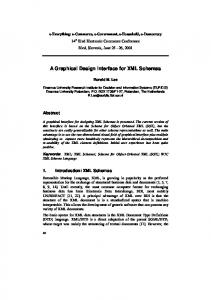
and then the program would generate the appropriate basic GUI objects that make up the composite meter object. 3.5 Application Domain Level Design Guidelines By using his own GUI object libraries the GUI designer can create user interfaces that have a consistent look. If he sticks to his own design guidelines, the resulting user interfaces will also have consistent feel to them. However, the ISO 11783 standard is currently missing application domain level design guidelines. Having and following those design guidelines would give all ISO 11783 applications a consistent look and feel. Design guidelines would be, as the name very clearly suggests – just guidelines, and unlike the standard they should not be followed to the letter. But even if half of the designers would follow the design guidelines half of the time, the machine control systems would provide a much more consistent user experience to the operators. 4. POOLEDIT PoolEdit is XML based, graphical editor for developing ISO 11783-6 graphical user interfaces. PoolEdit is open source software developed in the Automation technology laboratory at Helsinki University of Technology as a part of the Farmix project. PoolEdit is written in the Java programming language which makes it platform independent. The editor implements a multiple document interface and it has been tested on both Windows and Linux operating systems. 4.1 Editor Layout PoolEdit provides many views and other components for managing and editing object pools. The default layout is shown in Fig. 1. All views are dockable and the GUI designer can adjust them freely to best suit his working practices.
2) New objects are created by dragging them from the object toolbar to the tree model. 3) The object view shows how the objects will be rendered on the virtual terminal’s display. The object view can be zoomed and scrolled and it has various options for precise placement of objects. It is also possible to delete, resize and move objects in this view. 4) The tree view shows the objects in a single object pool. Although object pools are inherently DAGs, they can be visualized as trees. The tree view shows the types of objects, their names and how those objects are related. Multiple object pools can be open at the same time. Objects can be easily copied between and within the trees. 5) The XML view can be used for directly editing the generated XML code. This is useful for debugging but not needed for normal use. The message view (not visible in Fig. 1) is for displaying warning and other messages. 6) The attribute table shows the attributes and the attribute values of the selected object. The table has also different editors for editing different attribute types. For example, the GUI designer can select a color by picking it from a color list. Object attributes include things like object’s width and color while link attributes specify the position of the object or the role it plays in its parent object. 4.2 XML File Formats PoolEdit uses three different XML flavors for different purposes. Its native format is PoolEdit XML which is based on the IsoAgLib XML format (Spangler and Wodok, 2007). The biggest difference is that in PoolEdit XML only special link elements are used for linking, while in IsoAgLib XML many attributes are also used for linking. In PoolEdit XML links can only point to objects on the root level and only root level names have to be unique. A small sample of the generated PoolEdit XML is shown in Table 2. Embedded XML is designed so that it can be transformed to ISO 11783 binary format and sent to a virtual terminal. It is derived from the PoolEdit XML format, but there are a few differences. Embedded XML files include base64 encoded bitmap data which removes the need for separate image files. In addition, every object has been given a unique object ID which makes subsequent processing very efficient. Every object in Embedded XML is classified as a mask object or as a designator object. Mask objects are displayed on data and alarm masks. Designator objects can appear on working set, soft key and other designators. The classification makes object scaling easier if different scale factors are used for mask and designator objects. Using the same object on both mask and designator areas will generate a warning.
Fig. 1. PoolEdit’s default layout. 1) Menus are used for issuing file operations, running wizards and adjusting various settings.
For compatibility, PoolEdit can read and write IsoAgLib XML files. We have not used the IsoAgLib library or done any compatibility testing. There are some minor issues and limitations but in principle PoolEdit can be made to work with the IsoAgLib library.
1581
17th IFAC World Congress (IFAC'08) Seoul, Korea, July 6-11, 2008
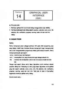
4.3 Wizards Wizards are small programs that generate GUI objects according to user’s specifications. The meter wizard is used to create meters with numeric scales and solid backgrounds. The meter wizard dialog is shown in the Fig. 2. The figure also compares the resulting composite meter object to a basic meter object.
results from a simple experiment are shown in Table 3. The compressed XML file is over ten times smaller than the original. It is even smaller than the binary presentation!
Table 3. Test pool size in different formats. Test Pool Format PoolEdit XML + image files Embedded XML Embedded XML compressed (GZIP) Binary pool size on the virtual terminal
Pool Size [kB] 258 263 24.6 34.7
The Embedded XML format is designed so that in can be processed with a simple runtime parser in a single pass. The lightweight, open source Expat7 parser is used for parsing XML files. Because VT resolution and color depth are known when the parsing starts, the parser can use this information to adapt the generated binary presentation accordingly. The parser scales objects and reduces their color depth to mach the capabilities of the terminal. 6. CONTROL SYSTEM ARCHITECTURE Fig. 2. Meter wizard dialog and the resulting meter object (top right) compared to the basic meter object (bottom right). Other implemented wizards include the table wizard for creating tables and the trend wizard for creating trend displays. These other wizards are very similar to the meter wizard and are not discussed in this paper. 5. RUNTIME XML PARSER
The machine control system is implemented with RTI's Constellation software development system. Constellation is an UML8 (OMG, 2007) based tool which is especially designed for implementing control systems. It provides a framework for building control systems from reusable software components. The control system design process and the Constellation tool are described in more detail in (Öhman and Visala, 2006).
The graphical user interface is loaded into the machine control system as an Embedded XML file. When the virtual terminal is detected on the network, the control system queries its properties, parses the XML file, and then loads an adjusted object pool to the VT. It is very useful to have the user interface in a separate XML file instead of having it in the executable. For example, it is possible to change the layout and the appearance of the GUI without recompiling or even restarting the control system! Another possibility is to use an external tool to convert the XML file into source code. The generated code can be compiled into the executable by including it to source files. The IsoAgLib library uses this approach. It has a conversion tool called vt2iso which parses XML files and generates C++ header and code files. The conversion tool is also responsible for extracting bitmap data from separate image files. The generated C++ files are then compiled with other source files to create the executable. Sometimes it is desirable to compile the object pool directly into the executable. The XML file can be included into the source code as a rather long string. Although XML is notorious for its verbosity6, the use of a compression algorithm, such as GZIP, can greatly reduce memory requirements. The
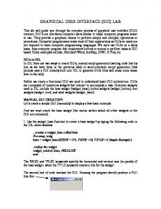
Fig. 3. Control system top-level components. The top-level components of a simple control system are shown in Fig. 3. The PeakDriver component encapsulates the CAN driver, which is needed for sending and receiving CAN messages. The FileAccess component hides the details of file operations and defines the default paths. 7
See project’s home page at http://expat.sourceforge.net UML (Unified Modeling Language) is OMG's (Object Management Group) most-used specification which has been accepted as an international standard (ISO/IEC 19501). 8
6
XML documents waste both memory and bandwidth.
1582
17th IFAC World Congress (IFAC'08) Seoul, Korea, July 6-11, 2008
The IsobusManager component contains the XML parser and other ISO 11783 functions, such as address management, packet transport protocols and VT initialization. It provides an interface for connecting GUI components that are proxies for VT user interface objects. The StartKey component is a proxy for a key object. The signal coming out of the component indicates the state of the key. The SpeedIndicator component is a proxy for a meter object. The signal going into the component indicates the reading on the meter.
objects. By listening the tag stream, a table proxy can learn not only its own properties but also the properties of its children. Table proxy’s own ID is not very interesting, because the table itself is only a container – the table data is stored in its children which are number field objects. Only by learning the properties of those objects, the table proxy can manipulate the table data. 6. CONCLUSIONS The presented XML based graphical user interface editor is designed to work with composite GUI objects. The editor supports GUI object reuse by allowing created objects to be stored in object libraries. Created library objects can be sorted on graphical displays so that they can be found more easily. In addition, the editor has some object wizards which are small programs that generate GUI objects according to user’s specifications. Describing user interfaces as structured documents allows efficient reuse of composite user interface objects such as entire displays. A runtime parser can be used to process XML files. The use of a compression algorithm, such as GZIP, can greatly reduce memory requirements. A compressed XML file can be even smaller than the binary object pool presentation. Because VT properties are known when the parsing starts, the parser can adapt the binary presentation accordingly.
Fig. 4. FSM for sending change numeric value messages. Internally, the proxy components are implemented as finite state machines (FSMs). The FSMs in Constellation are executable models that follow closely Harel’s statechart semantics (Harel and Gery, 1997) which are also the core of the UML state diagrams. Fig. 4 shows the internals of the SpeedIndicator component. When the VT is detected on the network, the FSM goes into the Active state where it sends a message to VT which holds the initial value. When it receives an acknowledgement it goes through a wait state into the Updated state where it remains until the value is changed. Together, the parser and the connected proxies form a distributed XML parser. Every time the parser processes a tag it notifies the connected proxies. When a proxy comes across tag’s name attribute that matches its own name, it can learn its own object ID by reading tag’s id attribute. In the same way, the proxy can also learn its other properties, such as its minimum and maximum values. This is immensely useful, because GUI objects can be configured only once in the GUI editor and the GUI proxies can learn their properties from the tag stream broadcasted by the XML parser. This means that the GUI proxies are basically configuring themselves and that the configurations are always in synch with the GUI objects. Because the Embedded XML has a real tree structure (i.e. it is not flat like the binary object pools), everything said in the previous paragraph can be generalized to composite GUI
In the presented control system architecture, the GUI objects are represented by corresponding proxy components. This architecture implements a distributed XML parser, which makes the proxies self-configurable. Every time the parser processes a tag it notifies the proxies. Proxies learn their properties by listening the tag stream. In this architecture, it is easy to create proxy components also for the composite GUI objects. This is a nice match between reusable software components and reusable GUI objects. REFERENCES Harel, D. and Gery E. (1997). Executable Object Modeling with Statecharts, IEEE Computer, 30:7 (July), 31-42. ISO (2004). Tractors and machinery for agriculture and forestry – Serial control and communications data network – Part 6: Virtual terminal (ISO 11783-6), International Organization for Standardization, Geneva, Switzerland. OMG (2007). Unified Modeling Language: Superstructure – Version 2.1.1. Object Management Group. Spangler, A. and Wodok, M. (2007). IsoAgLib – Development of ISO 11783 Applications in an Object Oriented way. http://www.isoaglib.org (2007-02-18) W3C (2007). Extensible Markup Language. The World Wide Web Consortium, http://www.w3.org/XML (2007-05-08) Öhman, M and Visala A (2006). Design and Implementation of Machine Control Systems with Modern Software Development Tools. In: Field and Service Robotics. Corke, P. and Sukkarieh, S. Ed, 377-388. Springer, Berlin.
1583