XML IN THE WORLD OF (OBJECT-)RELATIONAL DATABASE SYSTEMS Irena Mlynkova and Jaroslav Pokornya 1. INTRODUCTION XML1 is universally recognized as the standard for interchange and deviceindependent representation of information. On the other hand, XML is recently understood as a new approach to data modelling2, 3 A well-formed XML document or a set of documents is an XML database and the associated DTD or schema specified in the language XML Schema4 is its database schema. Implementation of a system enabling us to store and query XML documents efficiently is developed today in different ways. We do not discuss here native storage solution, i.e. a DBMS dedicated to manage XML data collections. A more practical possible solution can be found in storing XML data in (object-)relational DBMS. Moreover, this approach enables to provide XML with missing database mechanisms (e.g. indexes, transactions, multi-user access, etc.). Currently there is a relatively large number of works devoted to storing XML data, including the special architectures like PDOM, CMS, XML Servers, XML Query Engines, etc. We refer reader to Bourret2 for their comprehensive overview. Our contribution is a summarization of recent XML storage techniques based on today’s (object-)relational database technologies, their comparing and evaluation. We also present own algorithm for mapping XML Schema structures to object-relational (OR) schema. A more comprehensive discussion can be found in Mlynkova and Pokorny5. For transferring the data between XML documents and (O)R structures so-called mapping methods are of a great importance. A basic classification6 of existing mapping methods includes the following three classes: • • •
generic methods, which do not use any schema of stored XML documents, schema-driven methods, which are based on existing schema of stored XML documents, and user-defined methods, which are based on user-defined mapping.
Sections 2-4 contain an overview and possible classifications of the respective methods. Their evaluation and discussion is in Section 5. Section 6 provides conclusions. a
Charles University, Faculty of Mathematics and Physics, Department of Software Engineering, Malostranske nam. 25, 118 00 Prague 1, Czech Republic, {mlynkova,pokorny}@ksi.ms.mff.cuni.cz 1
2
I. MLYNKOVA AND J. POKORNY
2. GENERIC MAPPING METHODS Generic mapping methods do not use (possibly) existing XML schema of stored XML documents. They are usually based on one of two approaches – creating • •
a general (O)R schema into whose relations any XML document regardless its structure can be stored, or a special kind of (O)R schema into whose relations only a certain collection of XML documents having a similar structure can be stored.
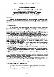
The former methods model an XML document as a tree T according to e.g. the OEM model or the DOM model, while the latter reflect its special “relational” structure. 2.1 Generic-Tree Mapping A typical representative of generic mapping is a group of methods called generictree mapping7. An example of an XML document and its T is depicted in Fig. 1. Irena person person Mlýnková 3 age 1 surname age 23 Podlesí 4943 name address name Zlín Beam 30 Jim Irena surname 2 Mlýnková Jim street city Beam Podlesí 4943 Zlín ...
Fig. 1. An example of a generic-tree
There are several methods for storing T, so-called edge, attribute, universal, and normalized universal mapping. Edge Mapping. This method stores all edges of T in the following table: Edge(source, ord, name, flag, target)
The table contains identifiers of nodes connected by the edge (source and target), name of the edge (name), a flag that indicates whether the edge is internal or points to a leaf (flag), and an ordinal number of the edge within sibling edges (ord). Attribute Mapping. In this mapping an extra table for each edge name (so-called attribute) is established. The structure of these tables is similar to the previous case: Edgename(source, ord, flag, target)
Universal Mapping. This method stores edges of T in so-called universal table, which contains columns for all the attribute names described in previous method. In other words, a universal table corresponds to the result of an outer join of all tables from attribute mapping. If a1,...,ak are all the attribute names in the XML document, the universal table can have the following structure: Uni(source, orda1, flaga1, targeta1,...,ordak, flagak, targetak)
XML IN THE WORLD OF (OBJECT-)RELATIONAL DATABASE SYSTEMS
3
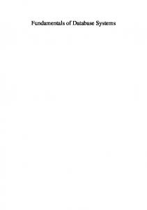
Obviously the universal table contains many NULL values. Normalized Universal Mapping. This method tries to solve the main disadvantage of universal mapping storing multi-valued attributes in separate, so-called overflow tables. An overflow table is established for each attribute name, while its structure is the same as in attribute mapping. The universal table then contains only one row per each attribute name, others are stored in corresponding overflow tables. There is also a plenty of variations of these methods. First, in all described approaches the values in leaves can be stored either in separate value tables (each holds values of a certain type) or in additional columns of existing tables. Other, so-called hybrid methods can be created using combinations of the described approaches. 2.2 Structure-Centred Mapping The structure-centred mapping8 considers all nodes of the tree T having the same structure defined as a tuple ν = (t, l, c, n), where t is the type of the node (e.g. ELEMENT, ATTRIBUTE, TEXT,...), l is the node label, c is the node content and n = {ν1,...,νn} is the list of successor nodes. The paper8 considers the problem how to realize mapping of the lists of successor nodes. It proposes three kinds of storage strategies focusing on speeding up the access performance. Foreign Key Strategy. Each tree node ν is simply mapped to a tuple with a unique identifier and a foreign key reference to the parent node. The method is quite simple and the stored tree can easily be modified. Nevertheless, its disadvantage is evident – the retrieval of the data involves many self-join operations. DF Strategy. In this strategy each node of T is given an index value (a couple of minimum and maximum DF values), which represents its position in T. The DF values are determined when traversing T in a depth first (DF) manner. A counter is increased each time another node is visited. If a node ν is visited the first time its minimum DF value νmin is set to the current counter value. When all child nodes have been visited, the maximum DF value νmax is set to the current counter value (see Fig. 2). ... Node1 (27,40) Node2 (28,31) Node3 (29,30)
Node4 (32,33) Node5 (34,39) Node6 (35,36)
Node7 (37,38)
Fig. 2. An example of DF indexing
Using DF values relationships of nodes (e.g. sibling order, element-subelement relationship, etc.) can easily be determined just by comparisons. For example, a node ν is a descendant of node µ, if νmin > µmin and νmax < µmax. Moreover, as the nodes can be totally ordered according to DF values, retrieving a part of a document is linear. The weak point of this strategy is document update – in the worst case it requires to update DF values of all nodes of the tree.
4
I. MLYNKOVA AND J. POKORNY
SICF Strategy. In this strategy each node of the graph is also given by an identification of its position – in this case so-called simple continued fraction (SICF) 1
σ= qk +
1 ... q2+
1 q1
where qi ∈ Ν (i = 1,...,k) are called partial quotients of σ and the expression partial quotient sequence. Sequences uniquely determine fractions and vice versa. The SICF values are determined in the following way: the root node gets a seed value s ∈ Ν, s > 1 (its SICF value is ). If a node ν has SICF value and has n ordered child nodes ν1,...,νn, then the SICF value for i-th child node is . The advantages and disadvantages of this strategy are similar to the previous one. 2.3 Simple-Path Mapping This method9 assumes that queries over the stored XML data are path queries of an XML query language. The main idea is to decompose XML documents into so-called simple paths and to store them in the database. Each simple path is based on the relation parent-descendant. Hence, each node in the graph retains its simple path. But as a simple path contains neither position nor order information, these two are stored in the graph too. The position information (called region) is a pair of a start and an end value, which are assigned as follows: Each word occurrence is assigned an integer number corresponding to its position within the document. Each tag is assigned a real number – its integer part indicates the position of the preceding word and its decimal part indicates the position of the tag being concerned in the current sequence of tags. The order information is composed of occurrence plus and occurrence minus order information, which expresses the index number of the node within its parent node (see Fig. 3). All the information about T is stored in following four relations: Element(docID, pathID, index, reindex, pos) Attribute(docID, pathID, attvalue, pos) Text(docID, pathID, textvalue, pos) Path(pathexp, pathID)
First three relations store information about each node type – document identifiers (docID), path identifiers (pathID), plus and minus occurrence order (index and reindex), regions (pos), attribute and text values (attvalue and textvalue). The relation Path stores simple paths (pathexp) and path identifiers (pathID). The main advantage of this method is apparent – storing simple paths of elements and attributes simplifies and speeds up processing path queries. 2.4 Monet Mapping The tree model of XML data in the Monet mapping10 is slightly different than in the previous methods (see Fig. 4). The main idea of this method is based on a complete binary fragmentation of T to binary associations, which describe different parts of the tree (edges, attributes, the topology of the document).
XML IN THE WORLD OF (OBJECT-)RELATIONAL DATABASE SYSTEMS
Designing XML applications Nick /book Marcus (0.1,7.3) Bob 0,-1 Pant /book/@style /book/title textbook (0.2,3.1) (0.1,0.1) 0,-1 /book/title Designing XML applications (1,3)
/book/author (3.2,7.2) 0,-1
/book/author /family (3.3,4.1) 0,-2
/book/author /given (4.2,5.1) 0,-2
/book/author /given Marcus (5,5)
/book/author /family Nick (4,4)
5
/book/author /family (5.2,6.1) 1,-1 /book/author /family Bob (6,6)
/book/author /given (6.2,7.1) 1,-1
/book/author /given Pant (7,7)
Fig. 3. An example of a simple-path tree
The associations, which bear semantically related information, are stored in relations together. Such information is related to definition of a path(o) as a sequence of (vertex and edge) labels along the path from the root node to o (where →e and →a denotes edge to an element and attribute, respectively), e.g.: path(o3) = bib →e article →e author path(“Ben Bit”) = bib →e article →e author →e cdata →a string
Each path then describes the position of an element in T relative to the root node. At the same time, path(o) is used to denote the type of binary association ( . , o). All associations of the same type are stored in the same binary relation. The advantage of this method is, that it avoids large and expensive scans over irrelevant data, the disadvantage is the high degree of fragmentation, which can increase efforts to reconstruct the original document or its parts.
Ben Bit How to Hack Ed Itor Ken Key Hacking and RSI
key
bib o1
key
"BB88"
article o2
author o3
title o5
author o8
author o10
title o12
cdata o4
cdata o6
cdata o9
cdata o11
cdata o13
string
string
string
string
"Ben Bit"
"How to Hack"
"Ed Itor"
article o7
Fig. 4. An example of a Monet tree
"Ken Key"
"BK99"
string "Hacking and RSI"
6
I. MLYNKOVA AND J. POKORNY
2.5 Table-Based Mapping A typical representative of the approach that enables to store only a certain collection of XML documents having similar structure is called table-based mapping2. It is based on the assumption, that the stored XML documents have a regular structure reflecting database, tables, rows, and columns. The mapping between elements and relations is exactly defined by the structure of the XML document. Apparently, this method is suitable especially for transferring the data between two relational DMBSs. 3. SCHEMA-DRIVEN MAPPING METHODS Schema-driven mapping methods are based on existing schema S1 of stored XML documents, written in DTD or XML Schema, which is mapped to (O)R database schema S2. The data from XML documents valid against S1 are then stored into relations of S2. The purpose of these methods is to create optimal schema S2, which consists of reasonable amount of relations and whose structure corresponds to the structure of S1 as much as possible. All of these methods try to improve the basic mapping idea “to create one relation for each element composed of its attributes and to map element-subelement relationships using keys and foreign keys”. 3.1 Common Characteristics Schema-driven mapping methods have several common basic principles6 resulting from information stored in the XML. The most important ones are: • • • • • •
Subelements with maxOccurs = 1 are (instead of to separate tables) mapped to tables of parent elements (so-called inlining). Elements with maxOccurs > 1 are mapped to separate tables. Elementsubelement relationships are mapped using keys and foreign keys. Alternative subelements are mapped to separate tables (analogous to the previous case) or to one universal table (with many nullable fields). If it is necessary to preserve the order of sibling elements, the information is mapped to a special column. Elements with mixed content are usually not supported. A reconstruction of an element requires joining several tables.
3.2 Possible Classifications The considered methods have several common features according to which they can be classified quite differently. Source XML Schema. An obvious classification is based on the type of S1. Most of these methods are based on DTD. The reason for this is, that although the DTD is quite simple, it is still sufficient for most applications. On the other hand, although the XML Schema is much more complex and thus difficult for learning, it contains useful features that DTD lacks and gives users more powerful tool for describing the allowed structure of XML documents. At present, there are also several methods (e.g. XMLSchemaStore mapping or LegoDB mapping), which try to exploit these features.
XML IN THE WORLD OF (OBJECT-)RELATIONAL DATABASE SYSTEMS
7
Target Database Schema. The methods differ also according to the S2. In this paper two possibilities are concerned – relational or object-relational approach. Most of the methods are based on the former one, since the relational databases and their features managed to gain more focus than others (including OR ones). Despite of this fact there are several methods, which try to take the advantage of OR features, such as NF2-relations (e.g. Hybrid object-relational mapping) or user defined data types and references (e.g. XMLSchemaStore mapping). Flexibility. Another classification6, 11 includes two classes – fixed and flexible methods. Fixed methods (e.g. Basic, Shared, and Hybrid algorithms, etc.) are those, which do not use any other information than S1 itself and whose mapping algorithm is straightforward. On the other hand, flexible methods (e.g. LegoDB mapping or Hybrid object-relational mapping) use the additional information (e.g. query statistics, element statistics, etc.) and focus on creating an optimal schema for a certain application. 3.3 Algorithms Basic, Shared, Hybrid, and Derived Algorithms The best-known representative of fixed schema-driven mapping methods is a group of three algorithms for mapping a DTD to relational schema called Basic, Shared, and Hybrid12. The main idea is based on a definition of a directed graph, so-called DTD graph, which represents the processed DTD. Nodes of the graph are elements (which appear exactly once), attributes, and operators (which appear as many times as in the DTD). Edges of the graph represent element-attribute, element-subelement or elementoperator and operator-subelement relationships. Each DTD is also first pre-processed and simplified to contain only ? and * operators and flat expressions (see Fig. 5). book article title * paper author ? surname name
published
Fig. 5. An example of a DTD graph
These algorithms try to gradually improve the idea “to create one relation for each element”. They differ according to the amount of redundancy they may cause. Basic Algorithm. The Basic algorithm combines two approaches: • •
to inline as many descendants of an element as possible and to create a relation for each element in the DTD graph.
In the former case only two kinds of element-subelement relationships are solved using keys and foreign keys – subelements with multiple occurrence (indicated by the use of * operator) and recursion (indicated by cycles in the graph). The main disadvantages of this algorithm are obvious – a huge amount of unnecessary relations and a great deal of redundancy since an element node can be represented in several relations.
8
I. MLYNKOVA AND J. POKORNY
Shared Algorithm. The Shared algorithm tries to avoid the drawbacks of Basic. The idea is to identify elements that are represented in multiple relations and to share them by creating separate relations for them. The mapping rules are: • • • • •
Nodes with an in-degree of one are inlined to parent relations. Nodes with an in-degree of zero are stored in separate relations. Repeated elements are stored in separate relations. Of all mutually recursive elements having an in-degree one, one of them is stored in a separate relation. The problem of inlined elements, which can become roots of an instance XML document, is solved using a flag for each element that indicates this state.
Apparently the main advantage of the Shared algorithm is the reduced amount of relations and redundancy. Its main disadvantage is the number of join operations necessary for restoring an element, which can be worse than in Basic. Hybrid Algorithm. The Hybrid algorithm tries to combine the join reduction properties of Basic with the sharing features of Shared. The algorithm is similar to Shared except for additional inlining of elements with an in-degree greater than one, that are neither recursive nor reached through a * node. CPI Algorithm. CPI (Constraints-Preserving Inlining) method13 can be based e.g. on the mentioned Hybrid algorithm. Its main purpose is to capture not only the structure of the DTD but the semantic constraints as well. The considered constraints are e.g. domain constraints, cardinality constraints (i.e. +, *, ? operators), referential integrity (i.e. ID, IDREF, IDREFS types), etc. These constraints are represented using corresponding SQL constraints e.g. NOT NULL, UNIQUE, PRIMARY/FOREIGN KEY, CHECK, etc. 3.4 Object-Relational Mapping Object-relational mapping14 uses the word “object-relational” in a bit confusing way, since it does not denote the type of S2 but the two steps of the algorithm. S1 is expressed either in DTD or XML Schema; S2 is relational in all cases. The two steps are: 1. 2.
S1 is mapped to an object schema expressed in an object-oriented language. The object schema is mapped to S2.
Obviously, if the object schema is not essential, it can be eliminated. The object schema models S1 as a tree of objects. In this step element types with PCDATA-only content and attribute types are considered as simple types. Element types with element or mixed content, or element types with attributes are considered as complex types. The mapping rules can be summed as follows: • • • • •
simple types → scalar data types, complex types → classes with each element type in the content model mapped to a property of the class – the data type of each property is either the scalar data type or a pointer/reference to the corresponding object, attributes → properties, subelements in a sequence or a choice → properties (whereas in the latter case the corresponding columns in the relational schema will be nullable), repeated subelements → multi-valued properties of (un)known size,
XML IN THE WORLD OF (OBJECT-)RELATIONAL DATABASE SYSTEMS
•
9
mixed content → a multi-valued property for storing PCDATA-values plus additional order columns for each property sharing the same order space.
An example of a DTD and associated schemes is in Fig. 6. DTD:
object schema: class A { String b; C c; }
relational schema: A(b,c fk)
class C { String d; String e; String f; }
C(pk,d,e,f)
Fig. 6. An example of object-relational mapping for DTD
For XML Schema the transformation is similar, the differences are related to additional features XML Schema has. The step doing object-to-relational transformation does not distinguish from usual approaches used in today’s software engineering. 3.5 Constraints Preserving Mapping Constraints preserving mapping15 preserves not only the structure of S1 but also the variety of semantic constraints XML Schema enables to express. XML Schema structures are formally represented by the regular tree grammar called FD-XML15. An extension of ER model, so-called EER model, is proposed and the FDXML is converted into EER schema. Then, the EER schema is simplified and optimized, preserving both the structure and the semantic constraints and finally, the simplified EER schema is converted to relational schema. The EER model uses (min, max) cardinalities, arrowheads modelling parent-child relationships, and accessories in order to preserve the data constraints (see Fig. 7). 1,1 E1