A SCALABLE HARDWARE ARCHITECTURE FOR HIGH PERFORMANCE ACOUSTIC BEAMFORMING Tamer Güdü(a), Taner Kolçak(a), Alper Bereketli(a), Selçuk Koçyiğit(a), Selçuk Alparslan(a) (a)
Underwater System Division, Meteksan Savunma A.Ş, 06800, Bilkent, Ankara, {
[email protected],
[email protected],
[email protected],
[email protected],
[email protected] }
ABSTRACT In this work a scalable hardware architecture is proposed to meet the system requirements of modern acoustic beamforming. The hardware architecture is composed of small processing units connected serially via high speed digital interface (Aurora, LVDS etc.). The functions of these units are (i) the conversion of analog signals received from the transducers and (ii) execution of the beamforming algorithm. Unlike the conventional approaches, the beamforming algorithm is implemented in a distributed manner. For this purpose a distributed hardware architecture for the implementation of frequency domain acoustic beamforming algorithm is proposed. The compiled results of experiments on the hardware are presented. It is seen that this approach has some advantages in terms of modularity, scalability, cost etc. The further details, advantages and disadvantages of the architecture are discussed in the paper. Keywords: Acoustics, Sonar, Beamforming, Signal Processing, Parallel Processing, Scalable Architecture. 1. INTRODUCTION The main functions of a sonar receiver unit are: 1. Analog processing of signals that are received from transducers. 2. Analog to digital conversion of signals 3. Beamforming, and 4. Execution of algorithms that involves target detection, localization and classification
1
The architecture of a sonar receiving unit shows some differences depends on the type of sonar, application area, and the avalailable technology. As an example, in a typical Hull Mounted Sonar (HMS) system that is widely used on commercial and military ships, the signals that are received from the transducers are carried through cables into the cabinets in the ship. In these cabinets the signals are converted into the digital domain and processed. Despite the advantages of this architecture that brings up as far as maintenance is concerned, cabling costs of the transducers are still high enough to cross off this architecture as an option. The system also suffers signal losses due to the distance between transducers and the cabinets. On the other hand in some sonar systems like FAS (Flank Array Sonar) due to the mechnical restrictions and requirements for noise immunity, the analog signals that are received from the transducers are converted into digital domain directly at the source and transferred to the main processing units digitally. Utilizing custom architectures for each different type of sonar systems requires specific designs of hardware and software architectures for each and every type of these systems and this would increase the non-recurring costs [1]. At this point the question is whether a sonar receiver architecture design that can be used for different SONAR applications? A modern sonar receiver architecture that will be designed in the light of todays technology should have the following features: 1. The signals that are received from the transducers or sensors should be converted into digital domain directly at the source. This would increase the noise immunity and decrease the crosstalk between audio signals. By this way, the signals that are converted into the digital domain can be transferred to the processing unit through the network of the sea vessels. 2. It should be modular and scalable.The number of transducers depends on the type or the system model of the sonar application. Thus, a modular and scalable receiver design that is composed of identical elements would (i) support different number of transducers, (ii) various sonar applications using the same architecture. 3. The maintenance should be easy and the possible failures that occur in the system should be removed quickly at a low cost. 4. It should be capable of sampling the transducer signals at a high data rate. The data bus that will be used to carry these signals should be fast enough to support the high number of transducers. 5. Some of the sonar algorithms like beamforming requires parallel processing. The execution of such algorithms on general purpose computer
2
cards may not always be feasible. The receiver unit should have dedicated processors to perform such algorithms. 6. Of course the cost is one of the main criteria that should be taken into consideration, especially for commercial sonar applications. In this paper a modular and scalable sonar receiver architecture, that is designed to meet the requirements of a sonar receiver with the features given above is presented. The architecture is discussed in two sections. In section 2 hardware and firmware of the architecture is explained in detail. In section 3 a distributed beamforming algorithm that is developed to use with this modular architecture is presented. The implementation details that make the architecture modular and scalable are illustrated with numerical examples. A discussion on the Pros and Cons of the proposed architecture concludes the paper. 2. HARDWARE ARCHITECTURE
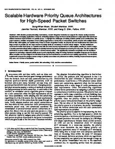
Figure 1 Architecture of Signal Processing Unit
3
The scalable hardware architecture that is proposed to meet the requirements given above is shown in Fig. 1. As shown in the figure the receiver hardware is composed of identical sub processing units and a signal processing computer. The sub processing units are serially connected to each other and accomplish data transfer between each other through LVDS lines (Low-Voltage Differential Signaling, EIA-644) or Gigabit Transceivers and Aurora data transfer protocol. Each LVDS pair supports 500Mbps data transfer and the data rate can be increased by increasing the number of LVDS lines [2]. Optionally Gigabit transceivers with Xilinx Aurora IP can be used to reach higher data rates. The throughput of the Gigabit transceivers are 2.5Gbps. The outputs of the serially connected sub processing units are connected to the main processing unit through ethernet interface. The function of the sub processing units are amplifiying and filtering the signal received from transducers, converting the analog signal into digital domain and processing the digital signal by the beamforming algorithm. The beamforming algorithm is implemented in a distributed manner.
Figure 2 Sub-processing Unit Block Diagram
The block diagram of the subprocessing unit is shown in Fig. 2. The subprocessing unit is composed of an analog processing part, an analog to digital converter (ADC) and an Field Programmable Gate Array (FPGA). The signals
4
that are received from the transducers are amplified and filtered by the analog processing unit and fed to the ADC unit and then to the FPGA. The two main functions of FPGA are data transfer between the cards and implementation of digital signal processing algorithms like digital filtering and beamforming. Inside the FPGA, the resulting data that are obtained through the beamforming algorithm is summed up with the data received from the previous sub-processing unit and is sent to the next processing unit through high speed data buses. In this distributed architecture the sub processing units are located nearby the transducers. By this way the signals received from the transducers are converted into digital domain directly at the source, minimizing the crosstalk between signals. The main difficulty in the implementation of the proposed hardware architecture is the synchronization of sub-processing units. The clock signal input to the ADC chips, should be in phase to ensure that all cards sample data at the same time instant. The analog to digital converters should also start to convert data to digital format at the same time. For this purpose an external synchronization signal is used. Figure 3 shows the picture of sub-processing card that is designed and manufactured in Meteksan Savunma Sanayii A.Ş. The physical dimensions of the card is 80mmx70mm and it is composed of 12 layers.
Figure 3 Sub Processing Card
5
3. DISTRIBUTED BEAMFORMING ALGORITHM Beamforming is a process of equalizing the phases of the signals and summing them up together on top of it to obtain an increase in the signal to noise ratio in proportional to the number of transducers. Beamfoming can be implemented in time domain (time domain beamforming) or frequency domain (frequency domain beamforming) [3]. In this work frequency domain beamforming algorithm is used because it is more suitable to implement on low cost FPGA chips. In frequency beamforming the sampling rate has a minimal effect on the performance of the algorithm and satisfying the wellknown Nyquist criteria is sufficient to recover signals from samples. On the other hand for time domain beamforming algortithm the sampling rate should be 5-10 times as high the rate of the highest frequency component [3]. The sampling rate required for the frequency domain algorithm is lower than time domain beamforming algorithm and it is one of the criteria that is taken into account in the selection of the algorithm. It is also notable that most of the SONAR digital signal processing algorithms that are used for detection localization or classification require frequency domain data of transducer signals and so the output of the frequency domain beamforming algorithm can be utilized directly [4]. In the frequency domain beamforming technique firstly the digital signals received from the transducers are multiplied with the shading coefficients that are necessary to reduce the effect of side lobes and obtain a narrower beam. The FFT algorithm is applied to get the spectrum of the signals. Time delays to attain required beam directions are calculated for each of the transducers in the array. Spectra of the signals received from the transducers are multiplied with the phase coefficients that correspond to calculated time delays [5]. Let's assume that the number of transducer is N, digital signal of the nth transducer is xn, the required beam direction is θm, the time delay at the nth transducer is tn(θm) and the shading coefficients are represented by θm. The spectrum of beam at direction θm is given by [3]: B( f , θ m ) = F {b(t , θ m )} N = F ∑ an xn [t − tn (θ m )] n=1
(1)
N
= ∑ an X n ( f ) e −i 2πftn (θm ) n=1
6
In this work, the frequency domain beamforming algorithm is implemented in a distributed manner. Each sub processing unit calculates the beams only for the transducers connected to itself and transfers them to the adjacent unit. The next unit also calculates the beam for the transducers connected to itself and sum the results with the beam data that comes from the previous card. Hence the resulting beams of the whole system are calculated though distributed summation technique. This structure is modular and scalable because the implementation of the beamforming algorithm is independent of the number of transducers. If the number of transducers or required number of beams is increased, it would be sufficient to add additional sub-processing units to the chain. Figure 4 shows block diagram of the FFT based distributed beamforming algorithm.
+ ....
....
....
+ + Figure 4 Scalable Beamforming Architecture
In this architecture utilizing the techniques to increase efficiency of source usage (e.g. time shared resource usage, run time calculation of direction coefficients), efficiency of sub processing units so the system can be increased for more transducers and number of beams [6].
7
4. IMPLEMENTATION RESULTS The FPGA resource usage for an example beamforming system with 8 transducers is shown in Table 1. In the example 16 number of beams are formed using 256 point FFT algorithm. As an FPGA chip Xilinx XC6SLX25T is used and price of this chip is around 50 USD [7]. To design a distributed system with 160 transducers, 20 number of sub-processing cards should be used and the cost of FPGA chips would be 20x50=1000 USD. If the same system is implemented on a single but a powerful FPGA like Virtex6, the FPGA resource usage would be as shown in Table 2. The price of the FPGA used in this system is 4300 USD [7]. Therefore, the cost of the distributed system is four times lower than the cost of the centric beamforming system.
Table 1 FPGA resource usage for distributed beamforming architecture FPGA
XILINX XC6SLX25T (Spartan 6)
Flip-Flop
7895
LUT
7514
Number of I/O
100
DSP
37
Block RAM
51 x 16 Kbit = 816 Kbit
Table 2 FPGA resource usage for centric beamforming structure FPGA
XILINX XC6VLX550T (Virtex 6)
Flip-Flop
160531
LUT
144710
Number of I/O
621
DSP
700
Block RAM
632 x 36 Kbit = 22752 Kbit
The resource usage on the single FPGA system can be reduced by increasing operating frequency and through time share resource using technique. However this increases the power consumption and timing and/or resource limitations may prevent implementation
8
5. CONCLUSION In the proposed system architecture, contrary to the conventional approaches, the beamforming algorithm is implemented in a distributed manner on the sub processing cards located close to the source. Such an architecture has the following advantages compared to the architectures with a single centric processor: 1. The signal is converted into digital domain at the source. This increases the noise immunity and reduces the crosstalk. 2. Thanks to the the scalable architecture, required processor performance can be achieved for cases where number of transducers, number of beams and frequency resolution are too high for implementation on a single centric processor. 3. Modular architecture can be used in different SONAR beamforming applications with minor modifications. 4. As the processing power of FPGA chips is increased, the heat disspated on the unit silicon area increases, leading to heating issues. This heat should be removed from the chips by using special heatsink designs or fans. In the distributed architecture the beamforming is implemented on several small FPGA chips instead of a single but powerful FPGA. Therefore the excessive heat is distributed overall architecture and the heat dissipated on unit silicon is decreased. The distributed systems suffer less from the heating problems compared to conventional systems. 5. In the proposed structure the beamforming algorithm is implemented on the sub-processing units. The output of these units are the spectrum of the signals passed through the beamforming algorithm. The data rate of spectrum information is lower than the data rate of the raw data. Hence the bus speed that is required between the sub-processing units are lower when the beamforming is implemented on these units. 6. The proposed architecture provides lower repair and maintenance costs. 7. In the proposed system the distance between the transducers and sub processing units are short. This quality eliminates the need for transferring analog signals from transducers to the analog to digital converters with long cables. The cabling of the proposed system is easy and can be done with a lower cost. The proposed architecture is designed, implemented and tested using a sample transducer array. The beamforming hands-on test results are
9
compared to the theoretical expectations . It has been observed that they match at a quiet certain level of confidence. With this work, in Meteksan Savunma Sanayii A.Ş., it is aimed to develop a SONAR receiver architecture that can be used for different applications with minor modifications to reduce the non recurring costs in the development phase. REFERENCES [1] M.A. Ainslie, (2010), “Principles Of Sonar Performance Modeling”, Springer Praxis Publishing. [2] S.B. Huq ve J. Goldie, (1998), “An Overview Of LVDS Technology”, National Semiconductor, Application Note 971. [3] R.A. Mucci, (1984), “A Comparison Of Efficient Beamforming Algorithms”, IEEE Transactions On Acoustics, Speech And Signal Processing, 3, 548-557. [4] A.D. George, J. Markwell ve R. Fogarty, (2000), “Real-time Sonar Beamforming On High-Performance Distributed Computers”, Parallel Computing (Elsevier), 26, 1231-1252. [5] W. S. Burdic, (1984), “Underwater Acoustic System Analysis”, Prentice Hall. [6] G. Hampson ve A. Paplinski, (1996), “Phase Shift Beamforming Using CORDIC”, ISSPA, 25-30 August, Brisbane, Austria. [7] Digi-Key Corporation, http://www.digikey.com/, February2012.
10