Differential Scanning Calorimetry (DSC) was made with a TA. Instruments Q1000. .... No obvious signature of PVDF is observed in these images. The image for ...
Effect of heat treatment on Si electrodes using polyvinylidene fluoride binder Jing Lia, L. Christensenb, M.N. Obrovacb, K.C. Hewittc and J.R. Dahnc, a a- Dept. of Chemistry, Dalhousie University, Halifax, NS B3H 3J5 Canada b- 3M Electronics Markets Materials Division, 3M Center, St. Paul, MN 55105, USA c- Dept. of Physics, Dalhousie University, Halifax, NS B3H 3J5 Canada
Abstract The electrochemical performance of Si electrodes using polyvinylidene fluoride (PVDF) binder heated at different temperatures ranging from 150°C to 350°C was investigated. Compared to unheated electrodes that have no capacity after the first formation cycle, the heat treated electrodes show an increasingly improved cycling performance as the heating temperature increases from 150°C to 300°C. In particular, Si electrodes heated at 300°C retain a specific capacity of about 600 mAh/g for 50 cycles with a lower cutoff potential of 0.170 V vs Li/Li+. The reasons for such improvements are considered based on results from thermal analysis, optical microscopy and adhesion tests. It is suggested that heat treatment improves the binder distribution, the adhesion to the Si particles and to the substrate, thereby leading to a better cycling performance.
1
Introduction The ever-increasing demand for energy density has driven lithium ion battery researchers to new generation electrode materials with high energy density. One of the approaches is to replace the conventional carbonaceous negative electrode material by a metal or a metallic alloy, particularly Si or Sn-based alloys. These alloy materials can provide much higher specific and volumetric capacity than graphite. However, this high lithium storage capacity is accompanied by large volume expansion during lithiation, which presents a huge challenge for capacity retention.
Some composite electrode
coatings containing alloy materials actually can not retain even 50% of their initial capacity after only a few cycles [1]. To mitigate these problems, many efforts have been devoted to optimize the metal or alloy materials. Starting from a single metal element, the most common approach is to make the material amorphous. It is believed that amorphous materials can eliminate the inhomogeneous expansion caused by the insertion of lithium atoms that occurs in crystalline materials [2]. Therefore, particle fracture and electrochemical pulverization can be efficiently avoided and the cycle life is improved. Some promising results from thin sputtered films of amorphous Si [3], Ge [4] and Si-Sn [5] have been reported. However, the sputtering method is probably not suitable for the economical production of large quantities of electrode materials. Another approach is to add inactive/active elements to the primary metal element. Amorphous or nano-structured alloys such as SiAlFe [6], SiC [7], SnCoC [8, 9], Tin oxides composites [10] and Sn2Fe/SnFe3C composites [11] have been proposed. The basic idea is to create a composite microstructure comprising a nanocrystalline or
2
amorphous active phase uniformly dispersed in an inert matrix. For instance, the addition of Co and C to Sn, as suggested by Inoue et al. [12]and by Dahn et al [8], produces a nanostructured material that shows a stable structure on the atomic scale, leading to promising cycle life with a specific capacity near 700 mAh/g. A number of alloys of this type can be prepared in bulk by mechanochemical synthesis (ball-milling, high-energy attrition), which makes them commercially attractive. A good example of this is the launch of 14430-sized lithium-ion batteries using an “amorphous Sn-Co-C negative electrode” by Sony in 2005 [12]. In addition, crystalline Si has attracted increased attention because of its high theoretical specific capacity and unique structural changes upon reaction with lithium. Unlike other metal elements, Si was found to become amorphous during the first lithiation [13, 14]. Obrovac and Krause [15] demonstrated that crystalline Si can be cycled normally between fixed-potential limits by carefully designing conditioning cycles. Powdered Si electrodes were reported to have better safety characteristics than graphite electrodes [16]. All of these studies combined with low-cost manufacturability of crystalline Si show that crystalline Si is a promising negative electrode candidate, although it still has some drawbacks such as low conductivity and large irreversible capacity. To summarize the discussions above, alloy materials need to be amorphous, nanoscale or nanostructured and be able to attain a stable microstructure over cycling to achieve the best capacity retention. Low cost synthesis methods need to be used to make commercial mass production feasible.
3
From a practical point of view, commercially viable negative electrodes typically comprise active material, carbon black and binder. Although the optimization of alloy materials contributes significantly to overcome the problem of capacity fading due to particle cracking, capacity fading caused by huge volume changes is still the Achilles’ heel for composite electrodes with amorphous alloy materials because of the significant motions of particles within a composite electrode during cycling [17]. For example, amorphous Si64Sn36 materials have good cycle life as binder-free sputtered films while amorphous Si64Sn36 composite electrodes using conventional PVDF binder show poor capacity retention [18]. It is believed that this problem is not caused by the active material itself, but by the polymeric binder that holds the active materials together [18, 19]. Therefore, the impact of binder selection on the performance of electrodes with alloy materials is significant. In contrast to the numerous papers on active materials, there are only a small number of studies on the role of binders apart from Japanese patent applications. Most new binders in the literature were proposed for graphite materials to improve electrode performance or eliminate safety issues. There are concerns that fluorinated polymers can react with lithiated graphite (LixC6) at elevated temperatures to form more stable LiF and >C=CF–double bonds. These exothermic reactions can contribute to thermal runaway [20]. Thus, non-fluorinated binders have been proposed for graphite electrodes including solvent-soluble polymers such as ethylene propylene diene terpolymer [21], silica-based gels [22], aromatic polyimide (PI) [23], poly(acrylonitrile-methyl methacrylate) [24] and water-soluble polymers such as cellulose [25], gelatin [26], sodium carboxymethyl
4
cellulose (CMC) together with emulsified styrene butadiene rubber (SBR) [27] and poly(acrylamide-co-diallyldimethylammonium chloride) [28]. Besenhard et al. [29] first showed the importance of the binder choice on the cycling behavior of metallic alloys. It was suggested that not only the nature of the binder but also its distribution within the composite electrode influences cycling performance. Chen et al. [17, 18] suggested that conventional PVDF binder contributes to the cycling failure of a-Si64Sn36 composite electrodes. Using a tether model, they proposed that an elastomeric binder system that has good adhesion to the active material particles should significantly improve the capacity retention of electrodes using amorphous alloy anode materials. Chen modified an elastomeric binder system, poly(vinylidene fluoridetetrafluoroethylene-propylene) (PVDF-TFE-P), to improve the capacity retention of aSi64Sn36 composite electrodes. Liu et al. [30] compared the cycle life of carbon coated Si materials using CMCcontaining SBR binder and PVDF binder. They explained that the enhanced cycle life of electrodes based on the SBR mixture binder is attributable to a larger elongation before break and a greater adhesion than PVDF binder. Buqa et al. [31] showed that 10% nano-Si containing graphite electrodes using 1% SBR/1% CMC binder have a better cycling behavior than ones using 10% PVDF binder. They concluded that the use of SBR and CMC binder enhanced the adhesion strength and their contents should be kept less than 6% to avoid hindering the lithium ion diffusion.
5
Li and Dahn [32] reported promising cycle life of Si electrodes made from crystalline Si powder (-325 mesh) and CMC binder. The electrodes using CMC binder had better capacity retention than those made using PVDF binder and also a binder consisting of CMC and SBR. Based on the fact that CMC is extremely stiff and brittle, it was suggested that mechanical properties are not the only factor that determines the performance of binders and other properties of binders such as surface modification need to be considered. Chen et al. [33] improved the cycling performance of 20% nano-Si containing Si/C composite and nano Si electrodes by replacing PVDF with acrylic adhesive binder. The performances were further enhanced by adding CMC because CMC was believed to help the distribution of the acrylic adhesive in the coating slurry, thereby improving the adhesion strength. All of these binder studies above clearly show that the choice of binder is very critical to the performance of composite electrodes with alloy materials. Improved binder systems are probably needed to evaluate new alloy materials because the incorrect choice of binder may cause confusion about the reasons for capacity fading.
The work
mentioned above also implies that PVDF binder may not be suitable for composite electrodes based on alloy materials.
Here, we introduce elevated temperature heat
treatment to Si electrodes using PVDF binder. The electrochemical results show that the heat treatment vastly improves the cycling performance of Si electrodes using PVDF binder. Heat treatment of electrodes for lithium ion batteries was previously reported by Palazzo et al. [34].
They patented the use of heat-treated electrodes containing a
6
polyamic-acid-PVDF binder mixture. The main purpose of their heating procedure was to thermally convert the polyamic-acid to polyimide and drive off water, the byproduct of the conversion of polyamic acid to polyimde. The heat treatment used here, however, serves a different purpose. In our studies, heated Si electrodes using PVDF binder show an enhanced adhesion to the Cu current collector. Combined with other test results, we believe that during the heat treatment, the PVDF binder filled with carbon black forms a more uniform distribution on the surface of the active material particles.
This results in
superior adhesion of the active materials to the substrate and also to better cycle life. It is not clear that the reason for the enhanced cycle life is due to the superior adhesion or due to a better coating of the binder on the particles leading to changes in the SEI.
Experimental
Preparation of PVDF-based Si electrodes Composite electrodes prepared here used 80 wt % silicon, 12 wt % super S carbon black and 8 wt % PVDF binder. 2.00 g crystalline Si powder (-325 mesh, Aldrich) and 0.300 g Super S carbon black (MMM Carbon, Belgium) were mixed and shaken for 1 hour at 500 shakes per minute. Four 12 mm diameter hardened stainless steel balls were used as the mixing media. 2.20 g PVDF solution [9 wt % Kynar PVDF 301F solution in N-methyl pyrrolidinone (NMP), NRC Canada] and 0.800 g NMP were then added and shaken for another half hour to form a slurry with a suitable viscosity.
7
The slurry was cast on a copper foil with a 75 µm high notch bar and dried at 90°C in air overnight. If needed, the dried electrodes were then heated under argon flow at a desired temperature for 12 hours using a Lindberg tube furnace. Typical active material loading was 2.6 ± 0.1 mg/cm2.
Electrochemical characterization The PVDF-based Si electrode served as the working electrode in a 2325-type coin cell using a lithium foil (FMC) disk as the counter and reference electrode. Two layers of microporous polypropylene (PP) separator (Celgard 2500) were used for each coin cell. The electrolyte used was 1 M LiPF6 (Stella, Japan) in a mixed solution of ethylene carbonate (EC) and diethyl carbonate (DEC) (volume ratio 1:2, Grant Chemical Ferro Division, USA). The coin cells were assembled and crimped closed in an Ar-filled glove box. The cells were discharged to 2000 mAh/g in a “formation cycle” before subsequent cycling between 0.17 and 0.9 V. The current used was 150 mA/g.
Preparation of PVDF films PVDF solution (9 wt%, in NMP) was cast on a piece of glass using a notch bar spreader. The samples were then dried at 90qC in air overnight and subsequently heated as desired. Some of the PVDF films were peeled off the glass and then cut into strips of suitable sizes to be used for thermal analysis.
Thermal analysis 8
Thermogravimetric analysis (TGA) was performed using a TA Instruments SDT Q600 apparatus. PVDF films were heated in an argon atmosphere to 600°C at a heating rate of 5°C/min.
Differential Scanning Calorimetry (DSC) was made with a TA
Instruments Q1000. A PVDF film weighing about 6 mg crimped in an aluminum pan was heated from 50°C up to 450°C at 5°C /min under nitrogen purge.
Images The surface morphology of PVDF-based Si electrodes was studied using a Hitachi S-4700 FEG Scanning Electron Microscope. The PVDF films cast on glass substrates were imaged with an optical microscope before and after heat treatment.
Adhesion test The adhesion of the PVDF-based Si electrode coating to the Cu foil current collector was tested using a 180° peel tester modified from a home-made stress-strain tester. The construction of this stress-strain tester is described in detail in reference [18]. The adhesion test sample was prepared as follows. One end of a PVDF-based Si electrode was adhered to a piece of stainless steel foil using Torr Seal epoxy and cut into 5 mm wide strips. The unattached end of the electrode strip was flipped over. This unattached end and the end of stainless steel strip were mounted on the 180° peel tester. When the actuator moves, the electrode coating peels off the Cu substrate while the peel force is measured with a load cell. Therefore, the adhesion measured here is the strength
9
required to pull apart the bonded interface between the electrode coating and the Cu substrate.
Results and Discussion Figure 1 shows the potential versus specific capacity for PVDF-based Si electrodes for the first 5 cycles. These PVDF-based Si electrodes underwent no heat treatment or heat treatment at different temperatures ranging from 150°C to 350°C for 12 hours in Ar. The maximum heating temperature used here was 350°C because PVDF decomposes at temperatures higher than 350°C according to the TGA results shown later. All the coin cells were first discharged to 2000 mAh/g, followed by cycling between 0.17 V and 0.9 V. The Si electrodes were cycled in this way so that enough amorphous Si is made during the first lithiation and only the amorphous phase is active in the amorphouscrystalline Si two-phase microstructure afterwards [15]. Electrochemical pulverization of the large Si particles, due to inhomogeneous volume expansion associated with coexisting crystalline intermetallic phases with different Li contents, is not expected. Thus excellent cycle life and coulombic efficiency can be obtained if the composite electrode based on Si is carefully designed. The failure of the composite electrode, if any, can be attributed to the binder performance. In Figure 1, the electrode without any heat treatment shows the largest irreversible capacity, more than 1500 mAh/g. The first cycle irreversible capacity decreases as the heating temperature increases from 150°C to 250°C. At heating temperatures higher than 250°C, the electrodes show an irreversible capacity of about 500 mAh/g. The heat treatment also shows a positive effect on the reversible capacity of PVDF-based Si 10
electrodes. The electrodes heated at temperatures higher than 200°C have reversible capacities up to about 750 mAh/g for the fifth cycle, while the electrodes heated at 200°C or below only show zero or little capacity. Irreversible capacity is usually caused by the following: (1) Some electrons and lithium ions are consumed during the irreversible formation of the Solid Electrolyte Interphase (SEI) on the electrode surface; (2) Some lithium atoms become trapped in the silicon particles; (3) The volume expansion of electrode during the first lithiation is so huge that some of the particles lose their electric contact, which causes permanent capacity loss. The third possibility is directly linked to the performance of the binder. It is well known that PVDF binder works well for commercialized carbonaceous materials that have only 10% volume change. By contrast, Si materials have a volume change up to 300% at fully lithiation [28], which presents a much greater challenge for PVDF binders. During the first formation cycle, the Si electrode delivered a capacity of 2000 mAh/g, corresponding to a volume change of about 168%.
Such a huge volume
expansion must break the PVDF binder during the first lithiation because PVDF only has an elongation of 20-30% before break [32]. In the following delithiation process, Si particles contract and some of the particles can not electrically connect to the main body of the electrode, thereby losing the corresponding capacity. As shown in Figure 1, the unheated electrodes show the largest irreversible capacity, which indicates the large amounts of Si particles lost electric contact to the electrode body after the formation cycle.
It appears that the performance of the composite improves as the heating
temperature increases.
11
Figure 2 shows the specific capacity versus cycle number for these PVDF-based Si electrodes that were heated at different temperatures for 12 hours. Every set of data includes data from two cells. After the formation cycle (2000 mAh/g), the electrodes show quite distinct cycling performances. The unheated electrodes show no activity at all right after the first formation cycle. The second cycle capacities for these electrodes increase as the heating temperature goes up. After 20 cycles, these electrodes show different extents of capacity fade. Their capacities at the 20th cycle follow a similar increasing trend with the increase of the heating temperature except for the electrodes heated at 350°C which have the worst capacity retention. Among these electrodes, the electrodes heated at 300°C show the best performance and retain a specific capacity of over 600 mAh g-1 for the first 50 cycles. Figures 1 and 2 clearly show that heat treatment improves the performance of Si electrodes using PVDF binder. Compared to the unheated electrodes, the electrodes heated at 300°C have a dramatically improved cycle life. This points out that not only the choice of binder but also the electrode treatment plays an important role determining the performance of composite electrodes. Figures 3a and b show TGA and DSC results for a PVDF film, respectively. There is an endothermic peak around 160°C in the DSC curve, which corresponds to the melting point of the PVDF polymer.
The melting point agrees well with the
specifications of Kynar PVDF 301F. TGA results show the onset temperature of PVDF decomposition is higher than 350°C, which corresponds to the sharp exothermal peak after 350°C in the DSC profile. The inset panel in Figure 3a shows that no obvious weight loss (less than 1 %) was observed at temperatures lower than 350°C. The heating
12
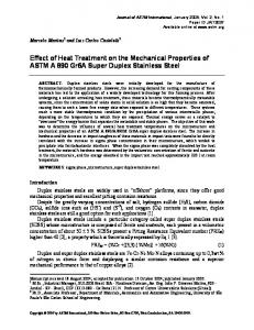
temperatures we used were no higher than 350°C, which indicates that the decomposition of the PVDF binder did not cause the cycle life improvement in Figure 2. However, the poor capacity retention of electrodes heated at 350°C may be attributed to PVDF decomposition. Figure 4 shows SEM images of PVDF-based Si electrodes.
The electrodes
contain 80 wt% Si, 12 wt% carbon black and 8 wt% PVDF. Both SEM images show Si particles with surface carbon black due the mixing of the dry Si and carbon black before mixing in the binder components. No obvious signature of PVDF is observed in these images. The image for the unheated electrodes is similar to the one for the electrode heated at 300°C. No useful information about the distribution of PVDF is provided by these images. Si electrodes with higher contents of PVDF binder with and without carbon black were also examined by SEM in our studies. There were no significant differences in the images of samples with and without heat treatments. Figures 5 a-d show optical images of PVDF films coated on glass without heat treatment and heated at 200°C, 250°C and 300°C, respectively.
The unheated PVDF
film shows a morphology containing small pores, while the films heated at 200°C or above have a smoother, less porous appearance. PVDF films cast on Si wafers were also investigated by an optical microscope and showed the same trend. For the sake of better clarity, only the images of the PVDF films cast on glass are shown here. According to Figure 3, the melting point of PVDF is about 160°C.
Therefore, during the heat
treatment at temperatures higher than 160°C, the PVDF film melts. A heating time of 12 hours allows the long tangled chains of PVDF to move around, flatten out and then recrystallize in the final cooling process. This heat-melt-cool process apparently gives
13
PVDF the opportunity to re-distribute and form a more continuous film on the substrate surface. These images help to understand why heat treated electrodes using PVDF binder have an enhanced cycling performance. A freshly prepared wet Si electrode using PVDF binder contains a certain amount of NMP solvent. The drying process removes NMP, which leads to a more and more concentrated PVDF solution within the electrode. As a result, PVDF is more and more viscous and has a high contact angle to the Si surface at the end of drying process. Discrete, dense lumps of carbon black-filled PVDF form on the surface of Si particles in a dried electrode. For PVDF-based Si electrodes heated at higher temperatures, the carbon-black filled PVDF polymer can flow and form a continuous coating on the surface of the active material which apparently leads to a better charge-discharge cycle life. This situation is similar to the case of gas diffusion layers in fuel cell membrane electrode assemblies. The gas diffusion layer is generally made of carbon paper coated with Teflon (polytetrafluoroethylene) or a Teflon-carbon black mixture, followed by thermal sintering [35, 36]. It was reported that higher sintering temperatures cause the Teflon to coat the paper fibers more thoroughly, thus allowing easier gas flow through the gas diffusion layer [36]. In our case, similarly, higher heat temperatures presumably are able to further lower the PVDF melt viscosity and affect cycling performance. Table 1 shows the adhesion strength of the electrode coatings to the Cu current collector for various samples as indicated. At least four samples were tested for samples with and without heat treatment. The adhesion was vastly improved after heat treatment, which may help to explain the improved cycling. According to our explanation above,
14
heat treatment apparently converts discrete, dense lumps of carbon black-filled PVDF into a uniform, continuous coating on the substrate surface. Thus the electrode coating has an area-to-area contact to the substrate instead of a dot-to-dot contact, thereby leading to better bonding with the substrate. The improved adhesion apparently leads to an improved cycle life. It is still surprising that Si electrodes using PVDF binder heated at 300°C can retain a specific capacity of 600 mAh/g for 50 cycles considering the extremely poor performance of electrodes without heat treatment. It appears that the distribution of the carbon black-filled binder within the composite electrode is very critical. It is not hard to imagine that a better binder distribution can lead to smaller interfacial impedance and better electric contact between active material particles. Especially for brittle binder systems that break easily when the active material has a huge volume expansion, it is important to have an excellent distribution of binder filled with carbon black to ensure good interfacial conductivity and keep the active material particles electrically connected. Although the PVDF monomer is very simple, PVDF is in fact a complicated polymer because it presents at least four crystal forms that depend on its thermal and mechanical histories [37, 38]. The reasons for the performance improvements of Si electrodes using PVDF binder after heat treatment might be more complex than we suggest above.
The role of heat treatment will be further studied by performing
mechanical property measurements, swelling tests, detailed DSC studies and so on. Tests of other PVDF-based fluorinated polymers are also underway. These results will be published in the future.
15
Conclusion In our work, heat treatment improves the cycling performance of Si electrodes using PVDF binder. The electrodes heated at 300°C show a capacity of 600 mAh/g for 50 cycles. The carbon black-filled PVDF apparently forms a better distribution on the surfaces of the Si particles after heat treatment, as supported by optical observations and adhesion tests. It is our opinion that the distribution of binder filled with carbon black is very important for improving the cycling performance of electrodes with large volume change alloy materials. This work shows not only the choice of binder but also other treatments have an influence on the performance of alloy composite electrodes.
Acknowledgments The authors acknowledge the support of this research by NSERC and 3M Canada under the auspices of the Industrial Research Chair program.
16
References [1] M. Winter and J. O. Besenhard, Electrochim. Acta. 45, 31 (1999). [2] L.Y. Beaulieu, T.D. Hatchard, A. Bonakdarpour, M.D. Fleischauer and J.R. Dahn, J. Electrochem. Soc. 150, A1457 (2003). [3] H. Jung, M. Park, Y.G. Yoon, G.B. Kim and S.K. Joo, J. Power Sources 115, 346 (2003). [4] J. Graetz, C. Ahn, R. Yazami and B. Fultz, J. Electrochem. Soc. 151, A698 (2004). [5] T.D. Hatchard, M.N. Obrovac and J.R. Dahn, J. Electrochem. Soc. 153, A282 (2006). [6] M.D. Fleischauer, M.N. Obrovac and J.R. Dahn, J. Electrochem. Soc. 153, A1201 (2006). [7] A. Timmons, A.D.W. Todd, S.D. Mead, Graham H. Carey, R.J. Sanderson, R.E. Mar and J.R. Dahn, J. Electrochem. Soc. 154, A865 (2007). [8] J. R. Dahn, R. E. Mar and A. Abouzeid, J. Electrochem. Soc. 153, A361 (2006). [9] A.D.W. Todd, R.E. Mar, and J.R. Dahn, J. Electrochem. Soc. 154, A597 (2007). [10] Y. Idota, M. Mishima, Y. Miyaki, T. Kubota and T. Miyasaka, U.S. Pat.5,618,640 (1997). [11] Ou Mao and J.R. Dahn, J. Electrochem. Soc. 146, 423 (1999). [12] http://www.sony.net/SonyInfo/News/Press/200502/05-006E/ [13] P. Limthongkul, Y.I. Jang, N.J. Dudney and Y.M. Chiang, Acta Mater. 51, 1103 (2003).
17
[14] Jing Li and J.R. Dahn, J. Electrochem. Soc. 154, A156 (2007). [15] M. N. Obrovac and L.J. Krause, J. Electrochem. Soc. 154, A103 (2007). [16] Y. Wang and J.R. Dahn, Electrochem. Solid-State Lett. 9, A340 (2006). [17] A. Timmons and J.R. Dahn, J. Electrochem. Soc. 153, A1206 (2006) [18] Zonghai Chen, L. Christensen and J.R. Dahn, Electrochem. Commun. 5, 919 (2003). [19] Zonghai Chen, L. Christensen and J. R. Dahn, J. Electrochem. Soc. 150, A1073 (2003). [20] H. Maleki, G. Deng, I. Kerzhner-Haller, A. Anani and J.N. Howard, J. Electrochem. Soc. 147, 4470 (2000). [21] L. Fransson, T. Eriksson, K. Edstrom, T. Gustafsson and J.O. Thomas, J. Power Sources 101, 1 (2001). [22] G. Oskam, P.C. Searson and T.R. Jow, Electrochem. Solid-State Lett. 2, 610 (1999). [23] N. Ohta, T. Sogabe and K. Kuroda, Carbon 39, 1434 (2001). [24] S.S. Zhang and T.R. Jow, J. Power Sources 109, 422 (2002). [25] J. Drofenik, M. Gaberscek, R. Dominko, F.W. Poulsen, M. Mogensen, S. Pejovnik and J. Jamnik, Electrochimica Acta 48, 883 (2003). [26] R. Dominko, M. Gaberscek, M. Bele, J. Drofenik, E. M. Skou, A. Würsig, P. Novák, and J. Jamnik, J. Electrochem. Soc. 151, A1058 (2004) [27] Jin-Hyon Lee, Sangkyu Lee, Ungyu Paik and Young-Min Choi, J. Power Sources 147, 249 (2005).
18
[28] S.S. Zhang, K. Xu and T.R. Jow, J. Power Sources 138, 226 (2004). [29] M.R. Wagner, M. Wachtler, M. Schmied, P. Preishuber-Pflugl, F. Stelzer, J.O. Besenhard and M. Winter, Abs #73 at 10th International Meeting of Lithium Batteries (IMLB 10), Como, Italy, (2000). [30] W.R. Liu, M.H.Yang, H.C. Wu, S.M. Chiao and N.L.Wua, Electrochem. Solid-State Lett. 8, A100 (2005). [31] H. Buqa, M. Holzapfel, F. Krumeich, C. Veit and P. Novak, J. Power Sources 161, 617 (2006). [32] Jing Li and J. R. Dahn, Electrochem. Solid-State Lett. 10, A17 (2006). [33] L. Chen, X. Xie, J. Xie, K. Wang and J.Yang, J. Appl. Electrochem. 36, 1099 (2006). [34] M. Palazzo and E.S. Takeuchi, U.S. Pat. 6,759,164 (1997). [35] D.P. Wilkinson, private communication. [36] D. Bevers, R. Rogers and M. von Bradke, J. Power Sources 63, 193 (1996). [37] B. El Mohajir and N. Heymans, Polymer 42, 5661 (2001). [38] C. Marega and A. Marigo, Eur. Polym. J. 39, 1713 (2003).
19
Figure captions: 1. Potential versus specific capacity for 5 cycles of cells having Si electrodes with PVDF binder. These PVDF-based Si electrodes were heated at different temperatures as indicated for 12 hrs in Ar and then compared to the ones without heat treatment. All the cells were first discharged to 2000 mAh/g, followed by cycling at 150 mA/g between 0.17 V and 0.9 V. 2. Specific capacity versus cycle number for two cells of each condition having Si electrodes using PVDF binder heated to different temperatures. The heating time was 12 hrs under Ar purge. All the cells were first discharged to 2000 mAh/g, followed by cycling at 150 mA/g between 0.17 V and 0.9 V. The first formation cycle (200 mAh/g) is not shown in order to show the rest of cycling clearly on the scale used. 3. a) Thermogravimetric analysis (TGA) and b) Differential Scanning Calorimetry (DSC) of PVDF solution-cast films. TGA was performed under argon purge to 600°C at a ramping rate of 5°C. The inset panel in a) focuses on the weight loss when the PVDF sample is heated up to 400°C. DSC was measured on a 6mg PVDF film crimped in an aluminum pan from 50°C up to 450°C at 5°C/min heating rate under nitrogen purge. 4. SEM images of a) PVDF-based Si electrode and b) PVDF-based Si electrode after heat treatment at 300°C for 12 hours. 5. Optical images of a) PVDF film on glass substrate, b) PVDF film on glass substrate after heat treatment at 200°C for 12 hours, c) PVDF film on glass substrate after heat
20
treatment at 250°C for 12 hours and d) PVDF film on glass substrate after heat treatment at 300°C for 12 hours.
21
Table 1. Adhesion strength of the electrode coating to the Cu substrate Sample No.
Heat treatment?
Adhesion (J/m2)
1
No
15-30
2
Yes (300°C for 12 hours)
80-100
27
Potential vs. Li/Li+ (V)
Figure 1
1.2 0.8 0.4 0 0.8 0.4 0 0.8 0.4 0 0.8 0.4 0 0.8 0.4 0 0.8 0.4 0 0.8 0.4 0 0.8 0.4 0 0.8 0.4 0 0.8 0.4 0
350°C
325°C
300°C
275°C
250°C
225°C
200°C
175°C
150°C
none
0
500
1000
1500
2000
Specific capacity (mAh/g) 22
Figure 2
Specific capacity (mAh/g)
1000
350°C 325°C 300°C 275°C 250°C 225°C 200°C 175°C 150°C None
800
600
400
200
0
0
20
40
60
Cycle number
23
80
100
Heat flow (W/g) weight retention (%)
Figure 3
100
a) TGA
80 100 60
99
40
98
20 0.8
0
100 200 300 400
b) DSC
0.4 0 -0.4 0
100
200
300
400
Temperature (oC)
24
500
600
Figure 4
a) No post-heat treatment
b) Post-heated at 300 °C
25
Figure 5 b) 200 °C
a) No postpost-heat treatment
50 μm
50 μm
c) 250 °C
d) 300 °C
50 μm
50 μm
26