exhibit excellent safety performance up to burn-up of about. 15 to 20% fissions ... because too much excess carbon deteriorates the performance of ZrC coating ...
Materials Transactions, Vol. 50, No. 11 (2009) pp. 2631 to 2636 #2009 The Japan Institute of Metals
Effect of Heat Treatment on TEM Microstructures of Zirconium Carbide Coating Layer in Fuel Particle for Advanced High Temperature Gas Cooled Reactor Jun Aihara1 , Shohei Ueta1 , Atsushi Yasuda2 , Hitoshi Takeuchi2 , Yasuhiro Mozumi2 , Kazuhiro Sawa1 and Yoshinobu Motohashi3 1
Oarai Research and Development Center, Japan Atomic Energy Agency, Oarai, Ibaraki 311-1393, Japan Nuclear Fuel Industries, Ltd., Tokai, Ibaraki 319-1196, Japan 3 Research Center for Superplasticity, Ibaraki University, Hitachi 316-8511, Japan 2
Japan Atomic Energy Agency (JAEA) has started to study and develop zirconium carbide (ZrC) coated fuel particles for advanced high temperature gas cooled reactors. The ZrC coating layer has been fabricated using the bromide process at JAEA. The coated particles with IPyC layers reported in a previous study were annealed at around 2073 K for 1 h, under which compact sintering will be done in a practical process, in order to study effects of the heat treatment (annealing) on their microstructure evolution. Then the microstructures of the ZrC layers in the cases (batches) of C/Zr = 1.11 and 1.35 were characterized by means of TEM and STEM. Microstructural evolution such as changes in the shape and size of voids or free carbons region caused by the heat treatment were found in the cases of both batches. After the heat treatment, the voids or free carbons region showed a clod like feature with diameters of 50 to 100 nm. The grain growth of ZrC was also observed in both cases: In the ZrC layer with C/Zr = 1.11, the fibrous carbons grew as if to stand from the PyC to ZrC layers on some places in the IPyC/ZrC boundary. [doi:10.2320/matertrans.M2009185] (Received May 22, 2009; Accepted August 24, 2009; Published October 15, 2009) Keywords: zirconium carbide, high temperature gas cooled reactor, fuel particle, heat treatment, transmission electron microscope, crystal growth, free carbon, microstructure
1.
Introduction
The high temperature gas cooled reactor (HTGR) is one type of nuclear reactors that utilizes ceramic coated UO2 fuel particles such as tri-structural isotropic or so-called TRISOcoated fuel.1) A spherical UO2 kernel is covered with a buffer layer, which is covered with an inner high density pyrolytic carbon (IPyC) layer. The IPyC layer is covered with the third layer, for which SiC has been used. The 3rd layer is covered with an outer high density pyrolytic carbon (OPyC) layer. The overall diameter of the TRISO-coated fuel is around 0.9 mm. The materials and the roles of each coating layer are described in Table 1. The very high temperature gas cooled reactor (VHTR) is a type of the HTGRs and is one of the most promising candidates for the fourth generation nuclear energy system. The VHTR fuel needs to be designed to exhibit excellent safety performance up to burn-up of about 15 to 20% fissions per initial metal atom (%FIMA) and a fast neutron fluence of 6 � 1025 m�2 (E > 0:1 MeV). It seems, therefore, that the VHTR needs fuel particles such as those processed by using advanced coatings, which can withstand at higher temperatures and to higher burn-up than the present TRISO-coated fuel particles. Recently, Japan Atomic Energy Agency (JAEA) has successfully developed a zirconium carbide (ZrC)-coated fuel particle, a ZrC coating layer, and it has demonstrated that the ZrC coated fuel particle possesses a much higher temperature stability than the present TRISO-coated fuel ones.2) In addition, it has been found that the ZrC coating layer has higher resistance to Pd corrosion than the SiC coating layer.3) JAEA has now started to investigate the following subjects related to the new coating layer: (1) ZrC-coating process up
to 200 g per batch scale with reduced excess carbon,4–6) because too much excess carbon deteriorates the performance of ZrC coating layer;7,8) (2) Inspection methods for the ZrC coating;6) and (3) Irradiation effects of the ZrC coated particles. We have already reported some characteristics of the microstructures of the ZrC layers with various C/Zr ratios including IPyC/ZrC boundary regions.9) Since the fuel particles are usually mixed with powder graphite etc., and then sintered into fuel compacts, it is quite significant to study the effects of the heat treatment that was imitated to the thermal history of the sintering process. In this study, the coated particles reported in our previous study9) are annealed at around 2073 K for 1 h, under the condition of which compact sintering will be performed in a practical process. Then the effects of the heat treatment on microstructure evolution of the coating layers are characterized by means of transmission electron microscope (TEM) and scanning transmission electron microscope (STEM) to obtain useful basic information for advancing the development of this new fuel. 2.
Experimental
The ZrC coating layer has been deposited on feed particle that is spherical IPyC-coated stabilized ZrO2 having an average diameter of around 0.8 mm. The surface of the feed particle is pyrolytic carbon (PyC), because the ZrC layer needs to be coated on the PyC in a practical process for the fuel particle. The diameter of the ZrO2 and the thickness of the IPyC layer were set to match those of the particle having UO2 kernel to be deposited with ZrC layer; it is because a proper condition for fluidization depends on the total weight
2632
J. Aihara et al. Table 1
Material and Roles of Each Coating Layer of TRISO-Coated Fuel.
Coating layer
Material
Buffer layer
Low density pyrolytic carbon
Plenum for gases (gaseous fission products, CO gas)
High density pyrolytic carbon
Retaining gases; Protecting UO2 kernel from the material gas during the deposition of the third layer
Inner pyrolytic carbon (IPyC) layer The third layer
Silicon Carbide (present)
Outer pyrolytic carbon (OPyC) layer
Batch code
�4
A-batch
C-batch�5
ZrC-06-2003
ZrC-06-2022
ZrC thickness (mm)
21
Main structural layer; Barrier for metallic fission products
Highdensity pyrolytic carbon
Table 2 Batch number (before heat treatment)
Role
9Þ
229Þ
Nominal deposition temperature [K]
9Þ
1769
16329Þ
Cushion for the third layer
Basic data of the specimens. XRD I200 /I111 �1 before and after annealing
9Þ
0.95 ! 0.87
1.329Þ ! 1.67
C/Zr ratio�2 (evaluated before heat treatment)
1.35
1.11
Density [g/cc]�3 (evaluated before heat treatment)
9Þ
6.01
6.459Þ
TEM specimen (after heat treatment) From about 10 mm under the PyC/ZrC boundary to about 7 mm above the boundary From the ZrC layer surface to about 5 mm under the surface�6 From about 9 mm under the PyC/ZrC boundary to about 3 mm above the boundary
�
1 ¼0:84 in powder diffraction. 2 evaluated by the infrared light absorption during combustion in oxygen and by the inductively coupled plasma-atomic emission spectrometry (ICP-AES).14Þ � 3 evaluated by the gas pycnometer method.14Þ � 4 Corresponding to A-batch described in Ref. 9). � 5 Corresponding to C-batch described in Ref. 9). � 6 resin embedding for the polished cross section of the particle. �
and the diameter of the particle. In addition, the UO2 kernel will be isolated from the material gas of ZrC by the existence of the IPyC layer. Accordingly, the deposition condition obtained will be transferable to a real UO2 system. The ZrC coating layer was of chemically vapor deposited (CVD) one produced by a bromide process.10) In the bromide process, the ZrC-coating layer is deposited with pyrolytic reaction of zirconium bromide, CH4 and H2 in a fluidizing bed in a graphite tube. Main reactions of the bromide process would be described as follows:10) ½CH4 � ¼ ðCÞ þ 2½H2 �
ð1Þ
½ZrBr4 � þ ½H2 � ! ½ZrBr3 �; ½ZrBr2 � þ ½HBr� ½ZrBrx � þ ðCÞ ¼ ðZrCÞ þ x½Br�(x ¼ 2, 3, or 4)
ð2Þ ð3Þ
½Br� þ ð1=2Þ½H2 � ¼ ½HBr�
ð4Þ
ð1=4ÞðCÞ þ ½HBr� ¼ ð1=4Þ½CH4 � þ ½Br�:
ð5Þ
The nominal temperature was kept almost constant, but locally the temperature fluctuated by about 80 K9) in the fluidized bed. The ZrC coated particles were annealed to know the effects of the fuel compact sintering process on microstructure evolution in the particles: The heat treatment condition was set so as to imitate the thermal history of the fuel compact sintering process for the High Temperature Test Reactor (HTTR) in JAEA: Firstly, the coated particles were heated in vacuum with the heating rate of about 200 K/min; Secondly,
they were kept at around 2073 K (2033 K) for 1 h; Finally cooled down to the room temperature with the cooling rate of about 140 K/min. Cross sectional TEM specimens of the ZrC layers were prepared by a focused ion beam (FIB) micro-sampling method using FB-2000A (Hitachi, Co. Ltd) with 30 kV Ga ions. The preparation was made without resin embedding for the polished cross-section of the particles except the specimens subjected to the heat treatment made from the C-batch including the surface of the ZrC layer. The TEM and STEM studies have been performed at room temperature with JEM-2000FX (JEOL, Ltd.) and HD-2000 (Hitachi, Co. Ltd.), respectively. Basic data of the specimens obtained from each batch are summarized in Table 2. The microstructures of the specimens obtained from these batches before the heat treatment have already been reported in our previous paper.9) 3.
Results and Discussion
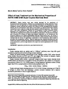
3.1 A-batch (C/Zr = 1.35) Figures 1(a) and (b) show the high angle annular dark field (HAADF) images including the IPyC/ZrC boundary of the TEM specimens before and after the heat treatment, respectively. The dark contrast areas seen in the ZrC layers correspond to voids or free carbons region.11) Before the heat treatment, the voids or free carbons region had a thin
Effect of Annealing on ZrC Layer in Fuel Particle for HTGR
(a)
2633
(b) ZrC
ZrC
500nm
IPyC
IPyC
500nm
Fig. 1 HAADF images of cross section of coating layer of A-batch including IPyC/ZrC boundary, (a) before heat treatment, (b) after heat treatment.
10nm
Fig. 2
TEM image of voids or free carbons: A-batch (after heat treatment). 200nm
(�10 nm) layered feature and were distributed densely (some 10 nano-meters interval)9) (see Fig. 1(a)). After the heat treatment, the voids or free carbons region changed to have a clod like feature with average sizes of 50 to 100 nm (Fig. 1(b)). They were distributed not randomly but, like roughly, lines, although the intervals of them were increased after the heat treatment. Moreover, the ZrC grains were slightly grown in this area. A TEM image of the clods of the free carbons or voids after the heat treatment is shown in Fig. 2. The free carbons region or voids show a brighter contrast than the surrounding ZrC grains. An aggregate feature of ribbons with widths of 5 to 10 nm was observed in each clod. The c-plane contrast of carbons was found in each ribbon along the elongated directions. Each ribbon would be free carbons.11) The free carbons showed a laminar feature with widths of 5 to 10 nm, and the c-plane contrast of carbons was observed in each free carbons region along the elongated directions before the heat treatment;9) that is to say, the free carbons region had a sheet like shape with the c axis roughly perpendicular to the thickness direction of the sheet before the heat treatment. Each sheet would be swept out to ZrC grain boundaries due to the growth of the ZrC grains, keeping the sheet like feature, though they became crumpled. The authors think that a main cause for the formation of such clods of the free carbons or voids would not be caused by the following process; the free carbons dissolved into the ZrC phase at high temperatures, and then precipitated as the specimen was cooled down to
Fig. 3 TEM image of IPyC/ZrC boundary region: A-batch (after heat treatment).
room temperature. It is because, we think, if the origin of the free carbons in the clods was the dissolved carbons in ZrC phase, they would not have such a strange and elastically unstable structure. The turbostratic carbons9) were observed on the IPyC/ZrC boundary similar to those observed before the heat treatment9) which is shown in Fig. 3 for reader’s convenience. No obvious change in the IPyC/ZrC boundary or IPyC microstructure was observed on TEM images, but the contrast seemed to be stronger than that before the heat treatment in these regions. The change in the structure in these regions can be detected by analyzing X-ray or electron diffractions quantitatively; this will be our next tasks to study. 3.2 C-batch (C/Zr = 1.11) Figures 4(a) and (b) show the HAADF images including the surface of a ZrC layer of the TEM specimens before and after the heat treatment, respectively. The dark areas, the same ones as the case of A-batch, correspond to voids or free carbons region.11) Before the heat treatment, the voids or free carbons region had a thin (�10 nm in thickness) layered feature and were distributed like lines being almost the same as those observed on A-batch9) (Fig. 4(a)). After the heat treatment, the voids or free carbons region had also almost
2634
J. Aihara et al.
(a)
(b)
500nm 500nm Fig. 4 HAADF images of cross section of coating layer of C-batch including surface of ZrC layer, (a) before heat treatment,9) (b) after heat treatment.
the same feature as those observed for A-batch (Fig. 4(b)). It is, however, evident that considerable crystal grain growth has occurred owing to the heat treatment. It is seen that the average grain size after the heat treatment is different from each other along the deposition direction. The average grain size along the deposition direction was approximately the same as to the above mentioned interval between the lines of the clods of the free carbons or voids (Fig. 4(b)). The average grain size was found to be the largest at the surface area of the ZrC layer (Fig. 4(b)). The change in the distribution of the free carbons or voids would influence the performance of the ZrC layer. The networks of free carbons or voids might be formed in the ZrC layer before the heat treatment, i.e., as-produced state, and the fission products (FPs) could diffuse a long distance along the networks.9) But the clods of the free carbons or voids may limit the formation of the network in the ZrC layer after the heat treatment, and accordingly the FPs cannot diffuse a long distance. On the other hand, the clods of the free carbons or voids on the grain boundaries of ZrC may weaken the binding of the grain boundaries. The normals of (200) planes of ZrC grains were broadly distributed to the deposition direction after the heat treatment (Fig. 5). This crystallographic orientation feature of the ZrC was quite similar to that observed before the heat treatment;9) this feature became more evident after the heat treatment. A probable reason why I200 /I111 ratio of XRD from the coated particles increased after the heat treatment (Table 2) would be that the feature of the orientation became more obvious, i.e., the 200 texture became stronger. The peaks from the crystal planes, of which normals tend to align parallel to the radial direction of the particle, were detected more clearly than other peaks, probably because the self-shielding effect for the incident and diffracted X-rays for these crystal planes would be weaker than others.9) Features of the free carbons were not clearly observed in the clods of the free carbons or voids after the heat treatment (Fig. 6). A main cause of this would be that the weight
500nm Fig. 5 TEM image including surface of ZrC layer: C-batch (after heat treatment).
density of these clods was much smaller than that of A-batch after the heat treatment: Note that this TEM specimen was prepared with resin embedding for polishing a cross-section of the particle, as described in section 2. No particular PyC structure existed at and near the IPyC/ ZrC boundary before the heat treatment,9) whereas particular PyC structures were found on the IPyC/ZrC boundary after the heat treatment (see Figs. 7(a) and (b)): In some regions on the IPyC/ZrC boundary, fibrous carbons with lengths of about 50 to 100 nm grew as if stand from the IPyC layer to the ZrC layer. It is interesting to note that under these standing fibrous carbons, other fibrous carbons are stuck one upon another (Fig. 7(a)).
Effect of Annealing on ZrC Layer in Fuel Particle for HTGR
2635
(a)
50nm 10nm
(b)
Fig. 6 TEM image of voids or free carbon after heat treatment: C-batch (after heat treatment).
The similar feature has already been observed on the IPyC/ZrC boundary in a batch that was subjected to oscillated deposition temperatures.11) It seemed that the fibrous carbons that aligned almost normal to the IPyC/ZrC boundary would be formed due to the tensile stress caused by the shrinkage of the PyC during the heat treatment.12) It has been shown that the tensile stress arises on the IPyC/3rd layer boundary in the coated fuel particles with the irradiation shrinkage of IPyC layer13) in an early stage of the operation of a reactor. The detachment of the IPyC/3rd layer can, therefore, be avoided, if the above mentioned mechanism works well to absorb the migration of the IPyC boundary under the operation temperature of the reactor. In an area on the IPyC/ZrC boundary, a flake of graphite was observed (Fig. 7(b)). This flake was well crystallized (see Fig. 7(c)) and its width and length were about 30 to 50 nm and a few micrometers, respectively. It is not evident at present whether this flake was introduced from the graphite tube, in which the ZrC layer was deposited or the structure of a part of the IPyC was changed into the graphite flake. No evident change in the IPyC microstructure was observed except for the boundary region on TEM images, whereas the contrast seemed to be stronger than that before the heat treatment in these regions, similar to A-batch. 4.
Conclusions
Changes in the microstructures due to the heat treatment of the ZrC layers in the cases of C/Zr = 1.11 and 1.35 were characterized by means of TEM and STEM; The heat treatment condition was set to simulate the fuel compact sintering process for the HTTR. The main results obtained are as follows: (1) Grain growth of the ZrC occurred during the heat treatment in the cases of both batches. (2) Shapes of the voids or free carbons region were changed to those having a clod like feature with diameters of 50 to 100 nm after the heat treatment. In the case of Abatch (C/Zr = 1.35), an aggregate feature of ribbons
100nm
(c)
5nm Fig. 7 TEM images of a region on IPyC/ZrC boundary: C-batch (after heat treatment), (a) ‘‘standing’’ fibrous carbons, (b) flake of graphite, (c) enlarged image of part of flake of graphite shown in Fig. 7(b).
with widths of 5 to 10 nm was observed in each clod. Each layer of the free carbons was swept out to the ZrC grain boundary owing to the grain growth of the ZrC, which might act to keep the sheet like feature, but the evolved microstructure was crumpled. (3) In the case of C-batch(C/Zr = 1.11), there appeared almost no change in the feature of the crystallographic orientation of the ZrC grains except that the feature of the orientation (a kind of texture) seemed to become stronger than that of the ZrC before the heat treatment. (4) In the case of C-batch(C/Zr = 1.11), the heat treatment led the fibrous carbons to grow as if to stand from the IPyC to ZrC layers on some regions of the IPyC/ZrC boundary. Furthermore, a flake of graphite was observed in an area on the IPyC/ZrC boundary, though this flake might be from the graphite tube.
2636
J. Aihara et al.
(5) In the case of A-batch(C/Zr = 1.35), no change in the structure of IPyC/ZrC boundary was seen on TEM images, while the turbostratic carbons were observed on the IPyC/ZrC boundary similar to that observed before the heat treatment. Acknowledgements Present study includes the result of ‘‘Development for Advanced High Temperature Gas Cooled Reactor Fuel and Graphite Components’’ entrusted to Japan Atomic Energy Agency (JAEA) by the Ministry of Education, Culture, Sports, Science and Technology of Japan (MEXT).
3) 4) 5) 6) 7) 8) 9) 10) 11)
REFERENCES 12) 1) K. Fukuda, T. Ogawa, K. Hayashi, S. Shiozawa, H. Tsuruta, I. Tanaka, N. Suzuki, S. Yoshimuta and M. Kaneko: J. Nucl. Sci. Technol. 28 (1991) 84–95. 2) T. Ogawa, K. Fukuda, S. Kashimura, T. Tobita, F. Kobayashi, S. Kado,
13) 14)
H. Miyanishi, I. Talahashi and T. Kikuchi: J. Am. Ceram. Soc. 75 (1992) 2985–2990. T. Ogawa and K. Ikawa: High Temp. Sci. 22 (1986) 179–193. A. Yasuda, S. Ueta, J. Aihara, H. Takeuchi and K. Sawa: JAEATechnology 2008-073 (2008). (in Japanese) A. Yasuda, S. Ueta, J. Aihara, H. Takeuchi and K. Sawa: JAEATechnology 2008–083 (2008). (in Japanese) S. Ueta, J. Aihara, A. Yasuda, H. Ishibashi, Y. Mozumi, K. Sawa and K. Minato: Hyomen 46 (2008) 222–232. (in Japanese) K. Minato and T. Ogawa: Proc. GLOBAL 2003, (New Orleans, LA, USA, 2003), pp. 1068–1074. T. Ogawa, K. Ikawa and K. Iwamoto: J. Nucl. Mater. 62 (1976) 322– 324. J. Aihara, S. Ueta, A. Yasuda, H. Ishibashi, Y. Mozumi, K. Sawa and Y. Motohashi: J. Am. Ceram. Soc. 92 (2009) 197–203. T. Ogawa, K. Ikawa and K. Iwamoto: J. Nucl. Mater. 97 (1981) 104– 112. J. Aihara, S. Ueta, A. Yasuda, H. Ishibashi, T. Takayama, K. Sawa and Y. Motohashi: J. Am. Ceram. Soc. 90 (2007) 3968–3972. J. D. Hunn, G. E. Jellison Jr. and R. A. Lowden: J. Nucl. Mater. 374 (2008) 445–452. J. L. Kaae: J. Nucl. Mater. 46 (1973) 121–133. S. Ueta, J. Aihara, A. Yasuda, H. Ishibashi, T. Takayama and K. Sawa: J. Nucl. Mater. 376 (2008) 146–151.