Abstract The fast injection of neutral particles for plasma formation and ... The spheromak turbulence plasma experiment (STPX) is a .... [1] C. A. Romero-Talamas, C. Holcomb, P. M. Bellan, and D. N. Hill ... high-speed imaging and magnetic diagnostics,â Physics ... [5] J. Anderson, Fundamentals of Aerodynamics, New York:.
Gas Injection Nozzles for Formation and Refueling of a Spheromak James E. Stuber, S. Woodruff, J.K. Baerny, A. Lueck Woodruff Scientific Inc., Seattle, WA, 98107 Abstract The fast injection of neutral particles for plasma formation and refueling is investigated here by use of solid nozzles. The necessary particle inventory throughput and speed is calculated and optimum nozzle geometries are determined for two specific applications.
1
Introduction
The fueling of plasmas for fusion applications is an important contemporary topic in the national fusion energy sciences program. Highly localized injection of particles is needed in order to control: 1) formation of plasmas with a Paschen-like breakdown; 2) refuel plasmas when particle inventories are lost by radial diffusion; and 3) cause a quenching of a plasma when catastrophic instabilities are onset. There are various techniques for forming and fueling plasmas for fusion research, such as pellet injection, beam injection and even ablative injection, although the most common is to use a gas puff (usually a solenoid-actuated needle valve) to locally inject particles. The problem with gas valve injection is that the flow is usually subsonic and not directional, giving poor control over the initial neutral gas pressures. This problem has been addressed by others [2, 3, 4] by use of gas nozzles, similar in many regards to jet-engine nozzles. We therefore take as a starting point their work, and apply the jetting of gas puffs to our experiment.
3 3.1
Theory
5
Supersonic nozzles
5.1
Mach number is defined as the velocity divided by the local speed of sound. V M= (1) a Isentropic relations for various conditions can be shown as a function of mach number as shown in Eqs. 2 and 3 [5]. T0 γ−1 2 =1+ M T 2 � �γ � � γ P0 ρ0 T0 γ−1 = = P ρ T
Results of modeling Injection for plasma formation
In formation, a desired trait was to have the entire plasma particle inventory (1020) injected into the gun just as the first particles reached the opposite electrode (in time τ ). In this way excess gas and therefore contamination could be minimized.
A A∗
�2
1 = 2 M
�
�
2 γ−1 2 1+ M γ+1 2
Discussion
Based on existing nozzles for refueling tokamaks [2, 3, 4] we have come up with a way to characterize and design nozzles for injection on the much smaller spheromak. The shorter lifespan of the spheromak in STPX necessitated as many as six refueling nozzles. Continuing the extrapolation of existing work, nozzles for gas injecting during the formation of a spheromak were designed. These nozzles will serve to improve the quality and confinement time of the spheromaks produced by STPX.
(2)
7
Further Work
(3)
Equation 4 shows that for a flow to become supersonic in a nozzle, the walls must first converge to a throat, then diverge. �
6
�� γ+1
γ−1
(4) Figure 4: Mach Number vs. τ (blue) and N/τ (green). The intersection indicates the conditions where the desired particle inventory will be in the gun just as the first particles hit the opposite electrode. An exit mach number of 1.75 and a particle injection rate of 1.76 x 10²³ mlc/s become our design parameters
Behavior of the gas as it leaves the nozzle is generally only known qualitatively; a good CFD analysis would help us to understand flow behavior better and improvements to the design could be made. At the small sizes used for these nozzles, investigation of viscous effects could also be useful. Real world testing would prove quite interesting. Actual performance could be compared with theoretical results to determine if our modeling is accurate. Testing of different types of nozzles could also be done. Probes could be used to test pressure profiles and spread angles of the gas as it leaves the nozzles.
Acknowledgements The STPX project is supported as a subcontract to WSI from Florida Agricultural and Mechanical University (FAMU). We would like to acknowledge the Washington NASA Space Grant program for supporting the lead author.
Figure 2: De Laval (top) and Conical Nozzle (bottom) [4]
3.2
Particle loss rate
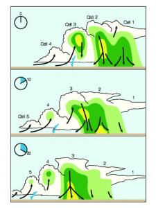
dni −ni = + 0.5n2i σv + Source (5) dt τ The plasma loses particles via radial diffusion at a particle i loss rate, dn dt . When the particle inventory of the plasma drops below a threshold (here 5 x 10¹⁹), the plasma ceases to form a spheromak. Therefore one way to extend the lifetime of a spheromak is to inject particles while it is in the chamber. Figure 1: STPX Gun and Chamber
4 2
Experiment description
Spheromaks are a special form of plasmas. The magnetic field created by self-generated plasma currents balances against the internal pressure, leading to a stable toroidal configuration. Spheromaks are considered a type of compact-toroid and are much smaller than mainstream tokamak designs. One way to form a spheromak is with a gun device. The gun is comprised of an two electrodes separated by vacuum. An initial bias field in produced by solenoid coils. Gas is injected in the gun. The electrodes are then brought to a large voltage difference, ionizing the gas and forming a plasma. J × B forces eject the plasma from the gun into the chamber. This process is shown in Fig. 1.
Design of Nozzles
The nozzle is to be mounted in a conflat port, flush with a gas valve. It will consist of an aluminum cylinder with the nozzle shape drilled out of the center. To simplify manufacturing and reduce the cost of the nozzle, a conical design was chosen over a laval design. Nozzle design is often constrained by the desired flow rate and exit mach number. These two values can be used to determine throat and exit areas.
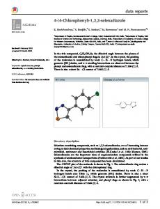
Figure 5: Throat Diameter (cm) vs. Particle Injection Rate (mlc/s). Rearranging Eqs. 2-4 gives the injection rate as a function of Throat Area, and therefore diameter [4]. Note that the desired particle injection rate of 1.76 x 10²³ mlc/s corresponds to a throat diameter of ˜0.65mm With M and throat diameter known, eq. 4 can be used to find that the exit diameter should be 0.77mm.
5.2
Injection for plasma refueling
For the injection nozzle, a moderate injection rate of 1023 mlc/s was chosen. Based on previous work, [4], a high but attainable exit mach number of 4 was chosen. Using eq. 5, the number of nozzles and pulse rate was to be determined.
[1] C. A. Romero-Talamas, C. Holcomb, P. M. Bellan, and D. N. Hill, ”Spheromak formation and sustainment studies at the sustained spheromak physics experiment using high-speed imaging and magnetic diagnostics,” Physics Of Plasmas, 13, 022502, Feb. 2006 [2] V. A. Soukhanovskii, H. W. Kugel, R. Kaita, R. Majeski, and A.L. Roquemore, ”Supersonic gas injector for fueling and diagnostic applications on the National Spherical Torus Experiment,” Review of Scientific Instruments, vol. 75, no. 10, pp. 4320-4323, Oct. 2004. [3] G. Martin et al., ”Plasma fuelling by pulsed supersonic Gas Injection on Tore Supra,” Fusion Montreux, vol. 26B, O-2.07, June 2002. [4] S. Collis et al., ”A supersonic gas injection system for fuelling and probing fusion plasmas,” Plasma Sources Science and Technolgy, 15, pp. 797-804, Sep. 2006. [5] J. Anderson, Fundamentals of Aerodynamics, New York: McGraw-Hill, 2007.
STPX The spheromak turbulence plasma experiment (STPX) is a device currently being designed and built by WSI. STPX will produce spheromaks of radius 1.5m which will last hundreds of µs. Behavior of turbulence in the plasma is to be studied.
References
Figure 3: Cutaway View of Formation Nozzle (left) and Refueling Nozzle (right)
Figure 6: Particle Inventory with respect to time, 6 refueling nozzles injecting at 1023 mlc/s. Injectors firing 50% (left) and 100% of the time (right). At 100%, the particle inventory rate is kept above the minimum value of 5 x 10¹⁹ for much longer than the duration of the shot.