distribution network. Over and above, scaling of the supply voltage may cause a large degradation in the signal-to-noise ratio of high speed CMOS circuits (Bai ...
10 Switching Noise in 3D Power Distribution Networks: An Overview Waqar Ahmad and Hannu Tenhunen
KTH Royal Institute of Technology KTH/ICT/ECS/ESD, Stockholm Sweden 1. Introduction The design and analysis of a power distribution network is one of the most important areas in high-speed digital systems. The main function of a power distribution network is to supply power to core logic and I/O circuits in any digital system. With increasing clock speeds accompanied by decreasing signal rise times and supply voltages, the transient currents injected into the power distribution planes can induce voltage fluctuations on the power distribution network (Tummala et al., 1997). This undesired voltage fluctuation on the power/ground planes is commonly known as switching noise or delta-I noise. Power supply noise leads to unwanted effects on the power distribution network (PDN) such as ground bounce, power supply compression, and electromagnetic interference. The digital switching noise propagates through the substrate and power distribution networks to analog circuits, degrading their performance in system-on-chip (SoC) applications (Iogra, 2007). The modern advances in process technology along with tremendous increase in number of on-chip devices make the design of on-chip power distribution network a major design challenge. Increased switching activity of high speed devices therefore causes large current derivatives or current transients. These current transients may cause unwanted potential drops in supply voltage due to parasitic resistance and inductance of power distribution network. Over and above, scaling of the supply voltage may cause a large degradation in the signal-to-noise ratio of high speed CMOS circuits (Bai & Hajj, 2002). When on-chip logic cells switch, either they draw current from supply network or inject current into the ground network. If a lot of logic cells switch simultaneously, then they may cause voltage variations within the supply network due to parasitic associated with the power distribution network. This voltage variation is nothing but core switching noise. It is called the voltage surge if variation is above the nominal voltage and is called the sag if variation is below the nominal supply voltage (Bobba & Hajj, 2002). This variation in supply voltage may cause logic errors thereby adversely affecting the circuit performance (Bai & Hajj, 2002). Excessive drop in power bus voltage or surge in ground bus voltage can cause following problems: decrease in the device drive capability, increase in the logic gate delay, and reduction of the noise margin. Hence, it is important to estimate these voltage variations in the power distribution network (Bai & Hajj, 2002). Simultaneous switching noise is mainly caused by the parasitic inductance associated with the power distribution network at high frequency. The power supply level goes down at different nodes in a PDN because of
210
VLSI Design
the inductive voltage drop at high frequency. This is because of the simultaneous switching of on-chip logic load as well as drivers connected to the output pins of a chip. The glitch in voltage caused this way is proportional to the number of circuit components switching at a clock edge, the steepness of the clock edge and effective inductance of the power distribution network at this moment. On-chip core switching noise as well as the noise caused by switching of the external drivers is equally important at high operating frequencies of the order of GHz. Scaling down of the technology node shrinks the minimum feature size which in turn increases average capacitive load offered by on-chip core logic. Therefore average charging and discharging currents for on-chip logic load increase. The increased circuit speed also raises di/dt. Therefore, on-chip currents may fluctuate by large amounts within short interval of times. Hence voltage fluctuations caused by switching of on-chip logic load known as core switching noise is very significant and important under these circumstance. On-chip power distribution noise has become a determining factor in performance and reliability where the core voltage has dramatically dropped to 0.9V for 40nm technology node (Shishuang et al., 2010) and the trend continuous. At the same time jitter tolerance and timing margins are shrinking due to ever increasing clock frequency (Shishuang et al., 2010). The chip-package PDN should therefore be optimized at early design stages to meet I/O jitter specifications and core logic timing closure (Bai & Hajj, 2002). For the IC designers and the signal integrity engineers, the most important issue is to understand how the on-chip transient current load interacts with the entire PDN system, and how the on-chip PDN noise affects the circuit performance (Shishuang et al., 2010). The experimental results in (Shishuang et al., 2010) show that on-chip PDN noise may be much higher even if PCB level PDN noise is well under control. On-chip noise margins decrease proportionally with the power supply with the scaling of the technology nodes (Coenen & Roermund, 2010). Generally the voltage fluctuation should be kept within 5-10% of the supply voltage in VLSI design (Dennis et al., 2008). When supply voltage is less than the nominal value in synchronous digital circuits, it causes timing violations in a register during a clock period (Dennis et al., 2008). This timing error caused by power supply noise may become permanent when stored in a register (Dennis et al., 2008). Core switching noise has been neglected in past due to higher package inductance as compared to on-chip inductance of the power distribution network. Therefore, switching noise was considered to be inductive voltage noise caused by fast switching I/O drivers (Bathy, 1996; Kabbani & Al-Khalili, 1999; Senthinathan & Prince, 1991; Vaidyanath, 1994;Yang & Brews, 1996). On the other hand today several folds increase in clock frequency as compared to I/O speed accompanied with higher integration densities and scaling of onchip interconnects has made the core switching noise more critical than ever (Zheng & Tenhunnen, 2001). The supply-noise becomes more problematic when microprocessors share the same substrate as the analogue circuits like PLL (Stark et al., 2008) (Vonkaenel, 2002). Therefore core switching noise may cause jitter in clock frequency thereby reducing the usable cycle time and consequently causing critical path failure in the processor. If core switching noise is extended over several clock cycles, then jitter accumulation will take place thereby causing deviation of each subsequent clock edge more and more from the ideal location (Larsson, 2002). The noise accumulation therefore causes synchronization failure between different clock domains more than the critical path failure. The other side effect of
Switching Noise in 3D Power Distribution Networks: An Overview
211
switching noise is substrate noise which may modulate the threshold voltage of MOS devices. Three-Dimensional (3D) integration is a key enabling technology in today’s high speed digital design. The purpose of 3D integration is either to partition a single chip into multiple strata to reduce on-chip global interconnects length (Joyner, 2004) or stacking of chips together through TSVs. By increasing the number of strata from one to four reduces the length of the longest interconnect by 50% with 75% improvement in latency and 50% improvement in interconnect energy dissipation (Meindl, 2002). Using 3D integration the wire-limited clock frequency can be increased by 3.9x and wire-limited area and power can be reduced by 84% (Miendl, 2003) and 51% (Khan et al., 2011) respectively. The power delivery to a 3D stack of high power chips also presents many challenges and requires careful and appropriate resource allocation at the package level, die level, and interstratal interconnect level (Huang et al., 2007). Three-Dimensional (3D) integration provides the potential for tremendously increased level of integration per unit footprint as compared to its 2D counterpart (Xie et al., 2010). While the third dimension introduced this way is attractive for many applications but puts some stringent requirements and bottlenecks on 3D power delivery. The huge current requirements per package pin for 3D integration lead to significant complications in reliable power delivery. A k-tier 3D chip could use k times as much current as a single 2D chip of the same footprint under similar packaging technology (Xie et al., 2010). Through silicon vias used in 3D integration introduce extra resistance and inductance in the power distribution path. The power distribution network impedance has not been kept up with the scaling of technology node due limited wire resources, increased device density and current demands (Xie et al., 2010) and situation is further worsened by 3D integration. The increased IR and Ldi/dt supply noise in 3D chips may cause a larger variation in operating speed leading to more timing violations (Xie et al., 2010). The supply noise overshoot due to inductive parasitic may aggravate reliability issues such as oxide breakdown, hot carrier injection (HCI), and negative bias temperature instability (NBTI) (Sapatnekar, 2009). Three-Dimensional (3D) integration increases integration density by increasing number of on-chip devices per unit footprint which has following effects with the scaling of technology nodes: • • • •
Tremendous increase in current per unit foot print. Increase in power per unit foot print. Increase in inductance per unit foot print at high frequency of the order of GHz. Consequent rise in switching noise imposed on 3D power distribution network.
Each power distribution TSV pair has to supply a logic load with decoupling capacitance. In order to increase the switching speed, the time constant RC needs to be reduced which means to reduce TSV resistance which is difficult with the scaling of technology node. Even if the instantaneous voltage fluctuation is very small, the periodic nature of digital circuits can cause resonance (Larsson, 1998). The resonance frequency due to effective TSV inductance and decoupling capacitance is given as follows
fr =
1 2π
Leff TSV C dec
212
VLSI Design
In order to prevent oscillations through a TSV pair the resonance frequency should be higher or lower than the system clock frequency. The effective resistance of TSV produces IR-drop, whereas reduces the resonance oscillations by providing damping. If simultaneous switching noise is dominant, the decrease in TSV effective resistance may increase the total noise in a 3D power distribution network. A three-dimensional (3D) stack of logic dies interconnected through TSVs has to connect the core logic circuits, IO circuits, and rest of the circuits from three-dimensional (3D) stack to the printed circuit board. Therefore, both the simultaneous switching noise and the core switching noise depend on high-speed switching currents through power distribution network in three-dimensional (3D) stack of dies, location and number of power distribution TSV pairs, vias and routing of various serial and parallel signal interfaces on signal layers of the package. The signal distribution TSV pairs share the IO power distribution environment. Three-dimensional (3D) power distribution network parasitic significantly account for core noise, significantly influence the simultaneous switching noise, crosstalk, signal propagation delay and skew between signal distribution TSVs. The transient currents drawn by core logic produce voltage droops across outputs of the core power distribution network thereby degrading the operating frequency performance of the microprocessor. Similar voltage droops are produced across IO power distribution network as a result of total transient current pulled through IO drivers and buffers. These droops weaken the signal driving capability of IO drivers thereby causing signal integrity issues.
2. Simultaneous switching in 3D power distribution network On-chip simultaneous switching noise is caused by switching of the output buffers or drivers as shown by Figure 1. These drivers have to drive the off chip load. The noise on Increase of maximum power (current)
I t
V=L
Increase of clock frequency
V=Vdd + V
Common Power Supply
H
I1 1
L
L I2
H
H
2
L
In
I= I1+ I2+....+ In
n
L L
Common Ground
Simultaneous Switching of Output Buffers Fig. 1. Simultaneous Switching of Output Drivers
Parasitic Inductance
Switching Noise in 3D Power Distribution Networks: An Overview
213
power distribution network depends on the parasitic inductance of the current path between the driver and the output load, the maximum current demand of the load, and the clock frequency.
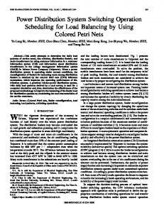
Fig. 2. (a) Configuration of three stacked chip-PDN connected by a multi-P/G TSV. (b) Simulated PDN impedances of a single chip-PDN (dotted line) and three stacked chip-PDN (solid and dashed lines) by the proposed separated P/G TSVand chip-PDN models. The Figure is taken from (Pak et al., 2011). The impedance peaks for the power distribution network of a three-dimensional (3D) stack of chips as compared to a two-dimensional (2D) chip is shown by Figure 2 (Pak et al., 2011). The impedance peaks are in GHz range and are created due to faster switching on the power distribution network. A huge amount of decoupling capacitance is required to suppress these peaks for a three-dimensional (3D) power distribution network (Pak et al., 2011). The impedance peaks are mainly generated due to TSV inductance at high frequency. Simultaneous switching noise causes the following problems: • Reduction of the voltage margins. Failure of the logic. • • Noise coupling to sensitive circuits like RF and analogue circuits. Circuit reliability degradation like decrease in the signal to noise ratio or increase in the • noise sensitivity.
214
VLSI Design
3. Core switching noise in 3D power distribution network Logic cells are connected between supply and ground TSVs for a three-dimensional (3D) power distribution network. Each logic cell has an equivalent capacitance as a load to the power distribution TSV pair. On-chip logic cells switch either low to high or high to low at different clock edges in a synchronous logic system. When on-chip logic cells switch, either they draw current from supply network or inject current into the ground network. If a lot of logic cells switch simultaneously, they may produce voltage variations within the supply network due to the parasitic associated with the power distribution network. This voltage variation is nothing but core switching noise. It is called voltage surge if variation is above the nominal voltage and is called the sag if variation is below the nominal supply voltage (Bobba & Hajj, 2002). The core switching noise depends on the on-chip power distribution network parasitic rather than the package parasitic because of the scaling of the interconnect in modern high speed ULSI design. In addition to that the core switching noise has become more on-chip centric as the package inductance is significantly less as compared to the onchip inductance at high frequency because of the introduction of BGAs and TSVs in modern packaging. The core switching noise is a major part of the total simultaneous switching noise as the current drawn by the core logic load is generally much higher than the I/O driver’s current (Radhakrishnan et al., 2007). The core switching noise in a threedimensional (3D) stack of logic dies interconnected through TSVs is more significant as compared to 2D ICs due to extra parasitic introduced through vertical TSVs. A large switching noise is introduced in a three-dimensional (3D) power distribution network if various stacked dies switch simultaneously (Huang et al., 2007). The number of power distributions TSVs for a three-dimensional (3D) stack of dies is basically limited by the footprint of the die (Jain et al., 2008) and on top of that the power supply noise is further worsened with the addition of dies in vertical stack due to additional parasitic involved in the power distribution paths through TSVs. The core switching noise can be a critical issue in a system like three-dimensional (3D) multi-processor system-on-chip (3D MOPSoC) (Tao et al., 2010). The core switching noise may introduce common mode noise in mixed analog and digital design as well as increase radiation at resonant frequencies. Overall power consumption in a three-dimensional (3D) stack reduces due to less interconnect, however, power density is increased in parts of three-dimensional (3D) stack due to increase in the number of transistors per unit volume as compared to two-dimensional (2D) counterpart. 3.1 Effects of core switching noise
While the third dimension is attractive for many applications but puts some stringent requirements and bottlenecks on three-dimensional (3D) power delivery. Huge current requirements per package pin for three-dimensional (3D) integration lead to significant complications in reliable power delivery. A k-tier three-dimensional (3D) chip could use k times as much current as a single two-dimensional (2D) chip of the same footprint under similar packaging technology (Xie et al., 2010). Through-silicon-vias used in threedimensional (3D) integration introduce extra resistance and inductance in the power distribution path. The power distribution network impedance has not been kept up with the scaling of the technology node due to limited wire resources, increased device density and current demands (Xie et al., 2010) and situation is further worsened by 3D integration. The increased IR and Ldi/dt supply noise in three-dimensional (3D) chips may cause a larger variation in operating speed leading to more timing violations (Xie et al., 2010). The supply
Switching Noise in 3D Power Distribution Networks: An Overview
215
noise overshoot due to inductive parasitic may aggravate reliability issues such as oxide breakdown, hot carrier injection (HCI), and negative bias temperature instability (NBTI) (Sapatnekar, 2009). The power delivery to a three-dimensional (3D) stack of high power chips also presents many challenges and requires careful and appropriate resource allocation at the package level, die level, and interstratal interconnect level (Huang et al., 2007). Any drop in the core supply voltage directly impacts the maximum operating frequency of the processor (Huang et al., 2007). Simultaneous switching noise originated from the internal logic circuitry has become a serious issue with the increase in speed and density of the internal circuitry. 3.1.1 Propagation delay
The voltage variations due to core switching noise are spread out to the diverse nodes of the power distribution network, thereby causing severe performance degradations in the form of propagation delays (Andarde et al., 2007). The timing violation in a register is produced when value of the supply voltage is less than the nominal value in a synchronous digital circuit. Due to slow variation of the supply voltage as compared to the clock period the value of the supply voltage may remain same for all the gates in a combinational path. Therefore, the value of supply voltage may vary period to period causing severe reliability issues is the logic. The logic cells are prone to more delays with the voltage scaling whereas keeping the threshold voltage relatively constant (Ajami et al., 2003). The propagation delay of the gates increases by 10% with 10% drop in the supply voltage for 180nm (Saleh et al., 2002), by 30% with 10% variation in the supply voltage for 130nm (Pant et al., 2004), and by 4% with 1% change in the supply voltage for 90nm technology node (Tirumuri et al., 2004). 3.1.2 Logic errors
The scaling of the threshold voltage with the scaling of the power supply voltage has reduced the noise margins, thereby making the CMOS circuits more vulnerable to the noise (Bobba & Hajj, 2002). The excessive drop in the power voltage or surge in the ground voltage may drop the noise margins of the circuits. Consequently, a circuit may erroneously latch up to a wrong value or switch at a wrong time if magnitude of the voltage surge/droop is greater than the noise margin of the circuit for a given clock edge (Pant et al., 2000). The problem is expected to grow for a three-dimensional (3D) stack of logic dies interconnected through TSVs, with the addition of each die in the vertical stack. 3.1.3 Impairing driving capabilities of a gate
The gates are becoming increasingly sensitive to the switching noise due to limited scaling of the threshold voltage as compared to the supply voltage scaling with each technology node (Junxia et al., 2009). The reduction in supply voltage not only reduces the noise immunity but also produces signal integrity as well as the performance and the reliability issues. The voltage spikes are droops produced in the power distribution network due to core switching because of the parasitic inductance and resistance associated with the power supply network. The excessive drop in power voltage or surge in the ground voltage, therefore, slows down the cell transition capability, thereby seriously compromising the cell driving capabilities. Consequently clock skews are produced as a result of violations in the setup and the hold times.
216
VLSI Design
3.1.4 Gate oxide reliability issue
With the scaling of power supply voltage the thickness of the gate oxide in modern CMOS VLSI circuits is very thin in order to reduce the nominal supply voltage (Ming-Dou & JungSheng, 2008). The excessive surge in power voltage or drop in ground voltage, therefore, may cause the transistor gate oxide reliability issue due to the electrical over-stress. 3.1.5 Hot carrier injection (HCI)
The channels of CMOS devices are already very short in length due to scaling with the technology nodes. Therefore, excessive surge in supply voltage or drop in ground voltage may cause the carriers to inject into the substrate or the gate oxide due to over voltage thereby depleting the drain-channel junction. It is called hot carrier injection and occurs when the transistor is in saturation (or switched). Consequently, it increases the switching time of an NMOS device and decreases the switching time of a PMOS device. 3.1.6 Cross coupling of through-silicon-vias (TSVs)
The results in (Liu et al., 2011) show that TSVs cause a significant coupling noise and timing problems even if TSV count is significantly less compared to the gate count. The core switching noise through power distribution TSVs may directly or through substrate couple to I/O drivers power supply network, signal links, clock lines, and analog components of the chip. In addition to that the core switching noise may couple to neighboring dies through TSVs for a three-dimensional (3D) stack of dies interconnected through TSVs as the substrates of different planes may essentially be biased through a common ground (Salman, 2011). Various inter-plane noise coupling paths have been identified in (Salman et al., 2010). The results in (Radhakrishna et al., 2007) show that I/O voltage is more sensitive to transient currents produced by switching of the core logic. Power distribution TSVs have significant capacitance due to larger in size as compared to signal TSVs and therefore, may produce significant noise coupling to substrate. The coupling noise from a power distribution TSV may cause path delay in signal line due to Miller effect. The coupling noise through power distribution TSVs may cause charge sharing to dynamic logic, thereby flipping the signal unintentionally or may change the state of a sequential element in static logic.
Fig. 3. Cross coupling of a TSV to nearby TSVs where M indicates the middle TSV and E, W, N, S, SE, SW, NW, and NE indicate the locations of closer TSVs to the middle TSV. The diagram is taken from (Roshan, 2008).
Switching Noise in 3D Power Distribution Networks: An Overview
217
Figure 3 shows the capacitive coupling of a given TSV to all the six TSVs arount it. This coupling depends on the distance of a TSV from other TSVs as well as the size of the TSVs. The capacitive coupling can be much stronger in bulky TSVs having significant hight. The coupling also, increases by increasing the density of TSVs. In addition to that, the coupling is inversly proportional to the thickness of the barrier layer around a TSV.
4. How to overcome core switching noise The core switching noise depends on the amount of logic load driven on rising/falling edge of the clock, sharpness of the clock edge (i.e. rise time), and nature of the network between power supply and logic load. The core switching noise can be reduced through different ways like placing on-chip decoupling capacitance close to the load, placing integrated decoupling capacitance with lower values of ESL and ESR into the substrate, keeping the output impedance across load as close to the target impedance as possible, and determining the optimum value of the damping factor for the power distribution network between supply and load. The rise time increases with the speed of the circuit and logic load increases with the integration density of transistors with each technology node and the problem is exacerbated for three-dimensional (3D) power distribution network. 4.1 Using on-chip decoupling capacitance
Decoupling capacitors are used as charge reservoirs to reduce the power supply noise during switching of the on-chip logic load. The decoupling capacitor is placed across the power and ground conductors to satisfy the target impedance that should be met at all the specified frequencies (Yamamoto & Davis, 2007). Practically, the decoupling capacitance is not a pure capacitance at high frequency because of the intrinsic effective series inductance and effective series resistance. Above the resonance frequency, the impedance of the decoupling capacitance appears inductive and the decoupling capacitance is therefore, not effective as desired above the self resonance frequency. Figure 4 (a) (Jakushokas et al., 2011) shows that the impedance of a power distribution network is resistive at low frequency, whereas it increases linearly with the frequency for higher frequencies due to the dominance of the inductive reactance of the network. There is a maximum frequency ωmax at which the network impedance exceeds the target impedance. Figure 4 (b) (Jakushokas et al., 2011) shows that the impedance of the network shoots up at the resonance frequency by using decoupling capacitance as compared to the no decoupling capacitance case. It is because of the parallel resonance produced by the LC tank circuit which produces the maximum impedance. However, above this frequency, the impedance starts increasing linearly with the frequency because of the dominance of the inductive reactance of the network at high frequency. Figure 4 (Jakushokas et al., 2011) shows that the target impedance is reached at a higher frequency when using decoupling capacitance as compared to without the use of decoupling capacitance. Therefore, decoupling capacitance is used to increase the frequency at which the impedance of the power distribution network exceeds the target impedance. The impedance of a decoupling capacitance is equal to the effective series resistance of a capacitor at the resonance frequency. A logic gate that is not switching connects its output
218
VLSI Design
load capacitance to either the positive supply or ground (Dally & Poulton, 1998). Thus, most of the time these output loads serve as symbiotic bypass capacitors that help maintain the supply voltage during current transients (Dally & Poulton, 1998). The method of calculating the symbiotic bypass capacitance is also given by (Dally & Poulton, 1998). The symbiotic bypass capacitance, therefore, enhances the strength of the intentional on-chip decoupling capacitance. However, too large decoupling capacitance reduces the resonance frequency of the power distribution network. Therefore, there is always a tradeoff between the resonance frequency and the amount of decoupling capacitance.
Impedance (log)
Without decoupling capacitance
Ztarget R total
R total Ltotal
ωmax =
Zt arg et Ltotal
Angular frequency (log) (a)
Impedance (log)
With decoupling capacitance
Ztarget R total
ωr =
1 LC
ωmax
Angular frequency (log) (b)
Fig. 4. (a) Frequency response of the impedance of a power distribution network without decoupling capacitance. (b) Frequency response of the impedance of a power distribution network with decoupling capacitance (Jakushokas et al., 2011). 4.2 Using integrated decoupling capacitance for 3D chip stack
The decoupling capacitors integrated into the Si substrate can provide high capacitance at low cost (Sharma et al., 2008). The integrated decoupling capacitors are famous for comparatively low effective series resistance and inductance at high frequency. The effective
Switching Noise in 3D Power Distribution Networks: An Overview
219
series resistance and inductance can be further brought down by inserting banks of small parallel decoupling capacitors in the substrate. The integrated decoupling capacitors provide noise immunity and improved power distribution for a monolithic threedimensional (3D) chips stack (Dang et al., 2009). Therefore, the integrated decoupling capacitors are more attractive for high frequency three-dimensional (3D) integrated systems.
5. Resonance and damping in 3D power distribution network There may be resonance oscillations in the power distribution network by adding on-chip decoupling capacitance (Bakoglu et al., 1990). A three-dimensional (3D) power distribution network has lower resonance frequency as compared to its two-dimensional (2D) counterpart (Jain et al., 2008). The resonance oscillations produced this way may cause worst case noise accumulation during subsequent clock cycles if not damped in a proper way. The on-chip decoupling capacitance should therefore be selected with a significant ESR (effective series resistance) in order to damp the resonance oscillations. The logic load on each die may have a resonance frequency as a result of the interaction between inductance of the power distribution TSV pairs and decoupling capacitance across the logic load. The damping is only required in the frequency domain around the resonance frequency, rather than at all the frequencies, therefore decoupling capacitance should be selected to have maximum ESR (effective series resistance) around the resonance frequency. The peak-to-peak ground noise on a power distribution TSV pair is given by (Larsson, 1998) through the following equation, assuming that TSV pair forms an under-damped system with damping factor less than one:
Δv pp
⎛ = Δv ⎜⎜ 1 + e ⎜ ⎝
πζ 1-ζ 2
⎞ ⎟ ⎟ ⎟ ⎠
Where Δv pp = Peak-to-peak ground noise on TSV pair. Δv = Peak ground noise on TSV pair.
ζ =
R eff TSV 2
C dec
Leff TSV
= Damping factor for the power distribution TSV pair.
R eff TSV = Effective series resistance associated with a power distribution TSV pair. Leff TSV = Effective series inductance associated with a power distribution TSV pair. C dec = On-Chip decoupling capacitance associated with a decoupling capacitance.
The performance and reliability of a three-dimensional (3D) power distribution network also depends on the magnitude and duration of the resonance oscillations. These oscillations must be controlled or significantly damped, otherwise noise accumulation will take place at subsequent clock cycles. The damping factor should have significant value in order to suppress the resonance oscillations. The effective resistance of a power distribution TSV pair should be kept much higher than the effective inductance of the power distribution TSV pair in order to increase the value of the damping factor.
220
VLSI Design
6. TSV-induced substrate noise in 3D integrated circuits Through-Silicon-Via (TSV) is a cylindrical metallic structure that is assumed to be used for power/signal distribution in a three-dimensional (3D) stack of dies. It has dielectric layer around it and normally passes through the Si-substrate in vertical direction. Figure 5 shows the cross section of a Si-Substrate with MOSFET transistor and TSV. Part of the Signal/logic switching transition though TSV can cross-through the barrier layer and may pass through the substrate and impact the performance of neighboring active devices and TSVs, known as TSV induced noise. It depends on TSV to device distance and substrate contacts. The transitions through TSVs may vary the body voltage VB of the MOSFET device. TSVsinduced substrate noise is almost directly related to the density of TSVs.
VTSV
Dielectric liner
GND tie dgt dTSV
VB
hTSV Si Substrate
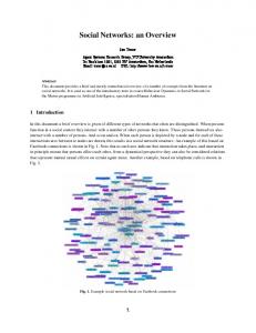
tliner Fig. 5. Cross-section view of TSV-to-device coupling (Khan, 2009, 2011). Figure 6 shows variations in the MOSFET device body voltage, VB, for different distances from a TSV for the set of design parameters shown by this Figure. The transitions are very short lived with only 50ps transition time.
Fig. 6. Body voltage during TSV signal transition at different distances, dTSV , for VTSV=1V square wave, hTSV=20um, tliner=1um, dgt=0.5um, signal transition time=50ps (Khan, 2009, 2011).
Switching Noise in 3D Power Distribution Networks: An Overview
221
7. Summary and future work On-chip switching noise for a three-dimensional (3D) power distribution network has deleterious effects on power distribution network itself as well the active devices. The extent of switching noise is related to the TSV density on one hand, whereas the integration density of on-chip devices on the other hand. Peaks of the switching noise largely depend on effective inductance of the power distribution network at high frequencies of the order of GHz. Therefore, efficient implementation of on-chip decoupling capacitance along with other on-chip inductance reduction techniques at high frequency is necessary to overcome the switching noise. In addition to that some accurate and efficient modeling techniques are also necessary for early estimation of the switching noise in order to lay down the rest of the design parameters for a three-dimensional (3D) power distribution network.
8. Acknowledgment The author would like to acknowledge European Union research funding under grant FP7ICT-215030 (ELITE) of the 7th framework program and Higher Education Commission (HEC), Pakistan, for the support of this work.
9. References Ajami, A.H.; Banerjee, K.; Mehrotra, A. and Pedram, M. (2003). Analysis of IR-Drop Scaling with Implications for Deep Submicron P/G Network Designs, Proceeding of IEEE International Symposium on Quality Electronic Design, ISBN 0-7695-1881-8, pp. 35-40, San Jose, CA, USA, March 2003 Andrade, D.; Martorell, F.; Pons, M.; Moll, F. and Rubio, A. (2007). Power Supply Noise and Logic Error Probability, Proceedings of IEEE European Conference on Circuit Theory and Design, pp. 152-155, ISBN 978-1-4244-1341-6, University of Sevilla, Seville, Spain , August 2007 Gen Bai, and Hajj I.N. (2002), Simultaneous switching noise and resonance analysis of onchip power distribution network. Proceedings of International Symposium on Quality Electronics Design, pp. 163-168, ISBN 0-7695-1561-4, Sanjose, California, USA, March 2002 Bakoglu H.B. (1990). Circuits, Interconnections and Packaging for VLSI, Reading, MA: AddisonWesley,1990 Bathey, K.; Swaminathan, M.; Smith, L.D.; and Cockerill, T.J. (1996). Noise computation in single chip packages. IEEE Transactions on Components, Packaging,and Manufacturing Technology, Vol. 19, No. 2, (May 1996), pp. 350–360, ISSN 1070-9894 Bing Dang; Wright, S.L.; Andry, P.; Sprogis, E.; Ketkar, S.; Tsang, C.; Polastre, R.; and Knickerbocker, J. (2009). 3D Chip Stack with Integrated Decoupling Capacitors. Proceedings of IEEE Electronic Components and Technology Conference, pp. 1-5, ISBN 978-1-4244-4475-5, June 2009 Bobba, S., and Hajj, I.N. (1999). Simultaneous Switching Noise in CMOS VLSI Circuits, Proceedings of IEEE Symposium on Mixed-Signal Design, pp. 15-20, ISBN 0-7803-55105, August 2002.
222
VLSI Design
Coenen, M.; and Roermund A.V. (2010). Noise Reduction in Nanometer CMOS. Proceedings of IEEE Asia-Pacific International Symposium on Electromagnetic Compatibility, pp. 1060-1063, ISBN 978-1-4244-5621-5, Beijing, China, April 2010. Dally and Poulton (1998). Digital System Engineering. Cambridge UK: Cambridge Univ. Press, 1998, pp. 237-242. Gang Huang; Bakir, M.; Naeemi, A.; Chen, H.; and Meindl, J.D. (2007). Power Delivery for 3D Chips Stack: Physical Modeling and Design Implication. Proceedings of IEEE Electrical Performance of Electronic Packaging and Systems, pp. 205-208, ISBN 978-14244-0883-2, Atlanta, GA, USA, November 2007 Jain, P.; Tae-Hyoung Kim; Keane, J.; and Kim, C.H. (2008). A Multi-Story Power Delivery Technique for 3D Integrated Circuits. Proceedings of IEEE International Symposium on Low power Electronics and Design, pp. 57-62, ISBN 978-1-4244-8634-2, Bangalore, India , August 2008 Jakushokas, R.; Popovich, M.; Mezhiba, A.V.; Köse, S.; and Friedman, E.G. (2011). Power Distribution Networks with On-Chip Decoupling Capacitors. Berlin, Germany: Springer-Verlag, 2011 Joyner, J.W.; Zarkesh-Ha, P.; and Meindl, J.D. 82004). Global Interconnect Design in a Three Dimensional System-on-a-Chip. IEEE Transactions on Very Large Scale Integration Systems,Vol. 12, No. 4, April 2004, pp. 367-372, ISSN 1063-8210 Junxia Ma; Lee, J.; and Tehranipoor, M. (2009). Layout-Aware Pattern Generation for Maximizing Supply Noise Effects on Critical Paths. Proceedings of IEEE VLSI Test Symposium, pp. 221-226, ISBN 978-0-7695-3598-2, Santa Cruz, California, USA, June 2009. Khan, N.H.; Alam, S.M.; and Hassoun, S. (2009). Through-silicon Via (TSV)-induced Noise Characterization and Noise Mitigation using Coaxial TSVs. Proceedings of IEEE International Conference on 3D System Integration, pp. 1-7, ISBN 978-1-4244-4511-0, San Francisco, USA, September 2009 Khan, N.H.; Alam, S.M.; Hassoun, S. (2011). Mitigating TSV-induced Substrate Noise in 3-D ICs using GND plugs. Proceedings of IEEE International Symposium on Quality Electronics Design, pp. 1-6, ISSN 1948-3287, SANTA CLARA, CA, USA, March 2011 Larsson, P. (1998). Resonance and Damping in CMOS Circuits with On-Chip Decoupling Capacitance. IEEE Transactions on Circuits and Systems I: Fundamental Theory and Applications, Vol. 45, No. 8, ISSN 1057-7122, August 2002, pp. 849-858 Larsson, P. (1999). Power Supply Noise in Future IC’s: A Crystal Ball Reading. Proceedings of IEEE Custom Integrated Circuits, pp. 467-474, ISBN 0-7803-5443-5, San Diego, CA, USA, August 2002 Liu, Chang; Song, Taigon; Cho, Jonghyun; Kim, Joohee; Kim, Joungho; Lim, Sung Kyu (2011). Full-Chip TSV-to-TSV Coupling Analysis and Optimization in 3D IC. Proceedings of IEEE Design Automation Conference, pp. 783-778, ISBN 978-1-45030636-2, San Diego, USA, August 2011 Meindl, J.D. (2002). The Evolution of Monolithic and Polylithic Interconnect Technology. IEEE Symposium on VLSI Circuit Design, pp. 2-5, ISBN 0-7803-7310-3, Honolulu, Hawaii, USA, August 2002 Ming-Dou Ker; and Jung-Sheng Chen (2008). Impact of MOSFET Gate-Oxide Reliability on CMOS Operational Amplifier in a 130-nm Low-Voltage Process. IEEE Transactions
Switching Noise in 3D Power Distribution Networks: An Overview
223
on Device and Materials Reliability, Vol. 8, No. 2, pp. 394-405, ISSN 1530-4388, June 2008 Jun So Pak; Joohee Kim; Jonghyun Cho; Kiyeong Kim; Taigon Song; Seungyoung Ahn; Junho Lee; Hyungdong Lee; Kunwoo Park; Joungho Kim. PDN Impedance Modeling and Analysis of 3D TSV IC by Using Proposed P/G TSV Array Model Based on Separated P/G TSV and Chip-PDN Models. IEEE Transactions on Components, Packaging, and Manufacturing Technology, Vol. 1, No. 2, pp. 208-219, ISSN 2156-3950, February 2011 Pant, M.D.; Pant, P.; Wills, D.S.; Tiwari, V. (2000). Inductive Noise reduction at the Architectural Level. Proceedings of IEEE International Conference on VLSI Design, pp. 162-167, ISBN 0-7695-0487-6, Calcutta, India, January 2000 Radhakrishnan, K.; Li, Y.-L.; and Pinello, W.P. (2001). Integrated Modeling Methodology for Core and I/O Power delivery. Proceedings of IEEE Electronic Components and Technology Conference, pp. 1107-1110, ISBN 0-7803-7038-4, Orlando, Florida, USA, May 2001 Roshan Weerasekera, System interconnection design trade-offs in three dimensional integrated circuits, PhD Dissertation: Royal Institute of Technology (KTH), Stockholm, Sweden, November 2008 Saleh, R.; Hussain, S.Z.; Rochel, S.; Overhauser, D. (2000). Clock skew verification in the presence of IR-Drop in the power distribution network. IEEE Transactions on Computer-Aided Design of Integrated Circuits and Systems, Vol. 19, No. 6, ISSN 02780070, August 2002 Salman, Emre; Doboli A.; and Stanacevic, M. (2010). Noise and Interference Management in 3-D Integrated Wireless Systems. Proceedings of the International Conference and Expo on Emerging Technologies for a Smarter World, September 2010 Salman, Emre (2011). Noise Coupling Due To Through Silicon Vias (TSVs) in 3-D Integrated Circuits. Proceedings of IEEE International Symposium on Circuits and Systems, pp. 1411-1414, ISNN 0271-4302, Rio de Janeiro, Brazil, July 2011 Sapatnekar, S.S. (2009). Addressing Thermal and Power Delivery Bottlenecks in 3D Circuits. Proceedings of IEEE Asia and South Pacific Design Automation Conference, pp. 423-428, 978-1-4244-2748-2, Taiwan, January 2009 Sharma, U.; Gee, H.; Liou, D.; Holland, P.; Rong Liu (2008). Integration of Precision Passive Components on Silicon for Performance Improvements and Miniaturization. Proceedings of Electronics System-Integration Technology Conference, pp. 485-490, ISBN 978-1-4244-2813-7, British Columbia, November 2008 Shishuang Sun, Larry D Smith, and Peter Boyle, On-chip PDN Noise Characterization and Modeling, DesignCon, January 2010 Strak, A.; Gothenberg, A.; Tenhunen, H. (2008). Power-supply and substrate-noise-induced timing jitter in non-overlapping clock generation circuits. IEEE Transactions on Circuits and Systems, Vol. 55, No. 4, pp. 1041–1054, ISSN 1549-8328, May 2008 Shuai Tao; Yu Wang; Jiang Xu; Yuchun Ma; Yuan Xie; Huazhong Yang (2010). Simulation and Analysis of P/G Noise in TSV Based 3D MPSoC. Proceedings of IEEE International Conference on Green Circuits and Systems, pp. 573-577, 978-1-4244-6876-8, Shanghai, China, June 2010 Tirumurti, C.; Kundu, S.; Sur-Kolay, S.; Yi-Shing Chang (2004). A Modeling Approach for Addressing Power Supply Switching Noise Related Failures of Integrated Circuits.
224
VLSI Design
Proceedings of Design, Automation and Test in Europe Conference, pp. 1078-1083, Paris, France, March 2004 Tummala, R.R.; E.J. Rymaszewski, and A.G. Klopfenstein, Microelectronics Packaging Handbook, pt. I, second edn. New York: Chapman Hall, 1997 Vonkaenel, V.R. (2002). A High-Speed, Low-Power Clock Generator for a Microprocessor Application. IEEE Journal of Solid-State Circuits, Vol. 33, No. 11, pp. 1634-1639, August 2002 Xie, Yuan; Cong, Jason; Sapatnekar, Sachin, Three-Dimensional Integrated Circuit Design, Integrated Circuits and Systems, Springer: 2010 Yamamoto, H.; Davis, J.A. (2007). Decreased effectiveness of on-chip decoupling capacitance in high-frequency operation. IEEE Transactions on Very Large Scale Integration System, Vol. 15, No. 6, pp. 649-659, ISSN 1063-8210, June 2007 Zheng, L-R; Tenhunen, H. (2001). Fast Modeling of Core Switching Noise on Distributed LRC Power Grid in ULSI Circuits. IEEE Transactions on Advanced Packaging, Vol. 24, No. 3, pp. 245-254, August 2001