CMM-2011 – Computer Methods in Mechanics
9–12 May 2011, Warsaw, Poland
Initial results of the finite element analyses of the closed cell aluminium foam microstructure under the blast load Danuta Miedzińska1 and Tadeusz Niezgoda2 1
Department of Mechanics and Applied Computer Science, Military University of Technology, Faculty of Mechanical Engineering Kaliskiego Street 2, 00-908 Warsaw, Poland e-mail:
[email protected]
2
Department of Mechanics and Applied Computer Science, Military University of Technology, Faculty of Mechanical Engineering Kaliskiego Street 2, 00-908 Warsaw, Poland e-mail:
[email protected]
Abstract The paper deals with the numerical modelling of the closed cell aluminium foam microstructure. The methods of such finite element modelling are presented. The specimen developed with the Kelvin structures is subjected to the blast load with the use of LS Dyna computer code. The applied load corresponds with the blast wave coming from the detonation of 100g TNT explosive. The results are presented as the deformations of the researched structure as well as the stress and pressure distributions. Such numerical analyses allow to limit the costs and risk connected with the detonation experiments that are carried out for the best blast wave protective material choice. The finite element researches allow to describe the main mechanisms in the microstructure and their influence on the macrostructural material strength behaviour. Keywords: porous media, microstructures, blast, numerical analysis
1.
Introduction
One of the possible options as a material for protective layers are aluminium foams which become very popular due to their energy absorbing properties. Metal foams are a new, as yet not sufficiently characterized, class of materials with low densities and novel physical, mechanical, thermal, electrical and acoustic properties. They offer potential for lightweight structures, for energy absorption, and for thermal management; and in some cases their low price is advantageous [1]. Energy absorption capacity of foams under blast load was analytically confirmed based on a rigid-perfectly plastic-locking foam model. In the present paper the development process of a foam microstructure based on finite element model Kelvin tetrakaidecahedrons is presented and applied to the blast load corresponding to the blast wave coming from the detonation of 100g TNT explosive.
geometrical solids (i.e. Kelvin’s polyhedron (Fig. 1) [2], Weaire-Phelan 8-cell repeatable structure (Fig. 2) [3] or on the way of Voronoi 3D tessellation [4]. Idealized models may represent multi cell structures or may be reduced to a repeatable fragment of geometry – single cell or their part, so they are convenient for fast comparative analysis of long series of differentiated models.
Figure 2: Weaire-Phelan repeatable structure
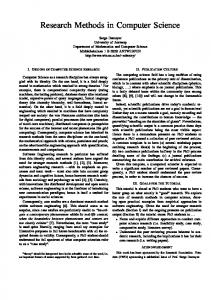
Figure 1: Kelvin tetrakaidecahedron 2.
Foam microstructure modelling methods
The idealistic models are often used for investigations of influence of particular geometrical or material parameters onto global properties of a foam. They may be built on the base of
The Kelvin foam, the three-dimensional analog of the honeycomb, is a perfectly ordered structure composed and obtained of identical bubbles that have the same shape and orientation. The Kelvin foam has cubic symmetry and the bubbles sit on a body-centered cubic (bcc) lattice. All of the films with the same number of sides and all of the edges have the same. The Kelvin foam is the only perfectly ordered structure known that satisfies Plateau’s laws. A Kelvin cell is a tetrakaidecahedron with six planar quadrilateral faces with curved edges and eight nonplanar hexagonal faces. Note that nonplanar films do not have to be spherical sections. The faces in a Kelvin foam have zero mean curvature because identical bubbles have equal pressure.
Figure 3 shows a typical model for an open cell porous material, which is assumed to represent the properties of the aggregate (voids and struts) of foams.
The values in the equation are described in Fig.5.
Figure 5. Pressure-time evolution during blast load Figure 3. Unit cell geometry and boundary conditions: (a) open structure; (b) simplified; (c) one-eighth; (d) under triaxial loads [5] Another method of creating the foam structure is to form a model from a tetrahedron and spheres which are cut out from its four vertices. The radii of the spheres will determine the porosity of the unit cell of the foam. Fig. 4 presents this methodology. The methodology is based on typical Boolean geometry.
In this case the blast loads is conveniently calculated using blast pressure functions such as ConWep which was developed by the US Army. The ConWep function can produce non-uniform loads exerted on the top surface of the plates. This blast function can be used in two cases: free air detonation of a spherical charge, and the ground surface detonation of a hemispherical charge. The input parameters include equivalent TNT mass, type of blast (surface or air), detonation location, and surface identification for which the pressure is applied. 4.
Numerical model description
The numerical model was built of the Kelvin unit cells of the dimension of 4 mm each and an aluminium plate. The total dimension of the model was 15×15×6 unit cells (60×60×24 mm). The porosity of the model was 85%. The model (Fig. 6) was built with four nodal shell elements. Figure 4. A tetrahedron and spheres to generate a unit cell of a foam [6]
3.
External blast load on structures modelling
Blast waves generated by the explosions of high explosive charges can damage or destroy structures. Numerical models are used to study these phenomena To precisely evaluate the blast propagation in the space around the structure and the structure response, FE models have to be used. Using a fluid structure interaction method (which exists in LS Dyna: *ALE, *CONSTRAINED_LAGRANGE_IN_SOLID) is also possible. Nevertheless, it generates big models fine 3D mesh, to define air from explosive to structure. Another possibility (also available in LS Dyna: *LOAD_BLAST), that was applied to the model, is to use an empirical model to compute the load on the structure. This solution is far less expensive in CPU and memory usage. When a high explosive detonates, a pressure front propagates into the surrounding atmosphere. This strong incident shock called the blast wave is characterized by an instantaneous increase from ambient pressure to peak incident pressure. Generally this shock is characterized by use of a Friedlander formulation (positive phase) [7]:
t t
t
P (t ) P 1 s so
o
t t
t
A exp
o
A
(1)
Figure 6. Finite element model of the aluminum foam microstructure The bilinear thin-shell element is a four-node, thin-shell element with global displacement and rotations as degrees of freedom. Bilinear interpolation is used for the coordinates, displacements and rotations. The membrane strains are obtained from the displacement field; the curvatures from the rotation field. The element can be used in curved shell analysis as well as in the analysis of complicated plate structures. For the latter case, the element is easy to use since connections between intersecting plates can be modelled without tying.
Table 1: Material properties for aluminium foam base material Aluminium alloy Young modulus Poisson’s ratio [GPa] PA25 71 0.33
The element is defined geometrically by the (x, y, z) coordinates of the four corner nodes. Due to the bilinear interpolation, the surface forms a hyperbolic paraboloid which is allowed to degenerate to a plate. The stress output is given in local orthogonal surface directions, V1, V2 and V3 (see Fig. 7) [8].
Yield stress [GPa] 0.318
Strength [GPa] 0,488
Elongation [-] 0.14
T=9e-5s
T=0,001s
Fig. 7. Form of the bilinear thin-shell element A piecewise linear plastic material model [9] was used for aluminium. The material properties for this model are presented in Table 1. The boundary conditions for the dynamic numerical analysis carried out with the use of LS Dyna computer code are presented in Fig. 8.
Figure 9. pressure distribution in the sample during the blast loading
Figure 8. Boundary conditions for the numerical analysis 5.
Finite element analysis results
The results of the blast numerical analysis are presented as: - pressure distribution in the sample during the blast loading (Fig. 9), - deformations of the single foam cell that is situated on the sample vertices below the explosive location (Fig. 10) during the blast loading compared to the undeformed structure, - von Mises stress distribution in the single foam cell that is situated on the sample vertices below the explosive location (Fig. 11) during the blast loading. The characteristic collapse for the foam cells, as well as the pressure and stress concentrations along cell edges are observed.
It is clearly visible that pressure distribution in the sample under the blast load is uniform, what is a very interesting phenomenon. It allows to draw a conclusion that the aluminium foam is a very effective material for constructions protecting against detonation (for example for military vehicles armours). The next interesting phenomenon is that the main deformation of the foam cell is a collapse into the cell volume. It is the main mechanism deciding about the material effectiveness during the blast load. It can be said that this deformation causes the highest energy absorption of the foamed structure [10]. The last observed behaviour of the researched structure was the von Mises stress distribution in the foam unit cell. The von Mises stress is used to predict yielding of materials under multiaxial loading conditions using results from simple uniaxial tensile tests. It is visible that the maximum of stress appeared on the external bended thin walls of the foam unit cell. The lowest stress value is inside the collapsed part of the structure, what shows that the damage of the researched material is caused by the local increase of the stress value around the area of the blast interaction.
undeformed
t=6e-5s Figure 10. Deformations of the single foam cell that is situated on the sample vertices below the explosive location during the blast loading compared to the undeformed structure
t=2e-5s
t=0
t=3e-5s t=2e-5s
t=4e-5s t=3e-5s
t=5e-5s
t=4e-5s
6.
t=5e-5s
Summary
In the paper the numerical modelling of the closed cell aluminium foam microstructure was presented. The methods of such finite element modelling were shown. The specimen developed with the Kelvin structures was subjected to the blast load corresponding with the blast wave from the detonation of 100g TNT explosive with the use of LS Dyna computer code. The results were presented as the deformations of the researched structure as well as the stress and pressure distributions. Such numerical analyses allow to limit the costs and risk connected with the detonation experiments that are carried out for the best blast wave protective material choice. The finite element researches enable a description of the main mechanisms in the microstructure and their influence on the macrostructural material strength behaviour. References [1] Ashby M., Metal Foams – A Design Guide, ButterworthHeinemann, 2002.
t=6e-5s
[2] Kraynik A. M., Reinelt, D. A., Linear Elastic Behavior of Dry Soap Foams, Journal of Colloid and interface Science 181, pp. 511-520, 1996. [3] Kutner R., Sullivan J. M., Comparing the Weaire-Phelan Equal-Volume Foam to Kelvin’s Foam, Forma, vol. 11 (No 3), pp. 164-330, 1996. [4] Lee K., Ghosh S., A microstructure based numerical method for constitutive modeling of composite and porous materials, Materials Science and Engineering A272, pp. 120-133, 1999.
t=7e-5s
[5] Ruan D., Lu G., Ong L.S., Wang B., Triaxial compression of aluminium foams, Composites Science and Technology 67, pp. 1218–1234, 2007. [6] Hang T., Lee J., A Plasticity Model For Cellular Materiale With Open-Celled Strukture, International Journal of Plasticity 19, pp. 749–770, 2003. [7] LeBlanc G., Adoum M., Lapoujade V., External Blast Load on Structures – Empirical Approach, 5th European LS Dyna Users Conference, France, 2005. [8] Marc 2007 r1 User Guide
t=9e-5s
[9] Compiled by Hallquist J. O., LS-Dyna Theory Manual, Livermore Software Technology Corporation (LSTC), March 2006. [10] Ergonenc C., Development and Design of Cosed-cell Aluminum Foam –Based Lightweight Sandwich Structures for Blast Protection, Doctor’s thesis, Izmir, 2008
t=0,0001s Figure 11. Von Mises stress distribution in the single foam cell that is situated on the sample vertices below the explosive location during the blast loading