1478
IEEE JOURNAL OF SOLID-STATE CIRCUITS, VOL. 46, NO. 6, JUNE 2011
1.8 V Low-Transient-Energy Adaptive Program-Voltage Generator Based on Boost Converter for 3D-Integrated NAND Flash SSD Koichi Ishida, Member, IEEE, Tadashi Yasufuku, Student Member, IEEE, Shinji Miyamoto, Hiroto Nakai, Makoto Takamiya, Member, IEEE, Takayasu Sakurai, Fellow, IEEE, and Ken Takeuchi, Member, IEEE
Abstract—In this paper we present an adaptive program-voltage generator for 3D-integrated solid state drives (SSDs) based on a boost converter. The converter consists of a spiral inductor, a high-voltage MOS circuit, and an adaptive-frequency and duty-cycle (AFD) controller. The spiral inductor requires an area of only 5 5 mm in an interposer. The high-voltage MOS circuit employs a mature NAND flash process. The AFD controller, implemented in a conventional low-voltage MOS process, dynamically optimizes clock frequencies and duty cycles at different . The power consumption, rising values of output voltage, time, and circuit area of the program-voltage generator are 88%, 73%, and 85% less than those of a program-voltage generator with a conventional charge pump, respectively. The total power consumption of each NAND flash memory is reduced by 68%. We also present the design methodology of the high-voltage MOS circuit of the boost converter with a conventional NAND flash process, in which charge-pump-based program-voltage generators are implemented.
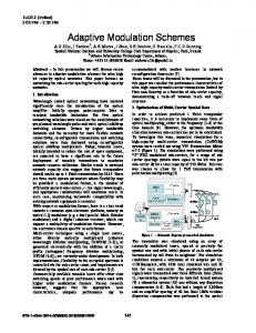
Fig. 1. Conventional SSD with charge pump.
Index Terms—Solid state drive, NAND flash memory, program-voltage generator, boost converter, charge pump, high-voltage MOS, adaptive controller.
I. INTRODUCTION
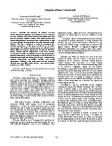
Fig. 2. Schematic of a typical conventional charge pump for NAND flash.
R
ECENTLY, solid-state drives (SSDs) have been widely used in various situations instead of hard disk drives. Decreasing the power consumption is the key design issue of SSDs. As shown in Fig. 1, a typical SSD consists of more than sixteen NAND flash memories, DRAMs, and a NAND controller. In a NAND flash memory, the write speed is slower than the read speed by one order of magnitude. Although the write speed must be improved, as a memory cell is scaled down or more bits are stored in the memory cell, more precise control of the threshold voltage in the memory cell is required, and therefore, it becomes
Manuscript received February 08, 2010; revised December 12, 2010; accepted March 09, 2011. Date of publication May 02, 2011; date of current version May 25, 2011. This paper was approved by Associate Editor Philip K. T. Mok. K. Ishida, T. Yasufuku, and T. Sakurai are with the Institute of Industrial Science, University of Tokyo, Tokyo 153-8505, Japan (e-mail:
[email protected]). S. Miyamoto is with the File Memory Device Engineering Department, Toshiba Corporation Semiconductor Company, Yokohama 235-8522, Japan. H. Nakai is with the Flash Business Strategy Development, Toshiba Corporation Semiconductor Company, Tokyo 105-8001, Japan. M. Takamiya is with the VLSI Design and Education Center, University of Tokyo, Tokyo 113-0032, Japan. K. Takeuchi is with the Department of Electrical and Information Systems, Graduate School of Engineering, University of Tokyo, Tokyo 113-8656, Japan. Digital Object Identifier 10.1109/JSSC.2011.2131810
difficult to accelerate NAND flash memories. Since the NAND write performance is 10 MByte/s [1], [2], to increase the write speed of an SSD to that of HDD (100 MByte/s), eight or more NAND chips in the SSD must be simultaneously programmed. As the feature size decreases, the bit-line capacitance rapidly increases. The total bit-line capacitance in a NAND flash memory exceeds 200 nF. If eight or more NAND chips operate simultaneously, an unacceptably large current of 800 mA flows to charge a huge bit-line capacitance in a sub-30 nm SSD [3]. In the conventional design, each NAND chip has a charge pump as a program-voltage generator. A schematic of a typical charge pump for NAND flash memories is shown in Fig. 2. The charge pump has serial MOS diodes consuming a large amount of energy and large capacitors providing an output current. As is decreased, the number of stages inthe supply voltage creases. One of the best strategies for decreasing the power of from 3.3 V to 1.8 V. Howthe memory core is to decrease ever, the power consumption of the conventional charge pump of 20 V greatly increases that generates the output voltage of 1.8 V. Therefore, the total power consumption of the at a NAND chips is not decreased as shown in Fig. 3. Furthermore, the charge-pump area more than doubles, which increases the NAND chip area by 5 to 10%.
0018-9200/$26.00 © 2011 IEEE
ISHIDA et al.: 1.8 V LOW-TRANSIENT-ENERGY ADAPTIVE PROGRAM-VOLTAGE GENERATOR
1479
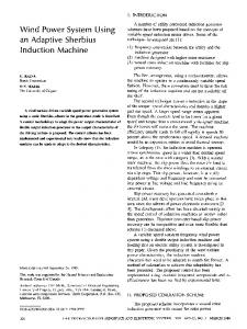
Fig. 5. Block diagram of boost converter for NAND flash in [4]. Fig. 3. Comparison of the consumed energy during write operation in NAND flash memories.
Fig. 4. Proposed 3D-SSD with boost converter in [4].
To overcome this problem, a low-power program-voltage generator with an adaptive-frequency and duty-cycle (AFD) controller was proposed [4]. The energy loss of the program-voltage generator is decreased by 88%. Moreover, by decreasing of the NAND chip from 3.3 V to 1.8 V, the total energy loss of each NAND flash memory is decreased by 68% as shown in Fig. 3. Fig. 4 shows the structure of our 3D-integrated SSD. NAND chips, DRAMs, a NAND controller, and the program-voltage generator are integrated as a system-in-a-package (SiP). Fig. 5 shows a block diagram of the proposed program-voltage generator, which consists of an inductor in an interposer, a highvoltage MOS circuit, and the AFD controller. In the proposed system, the cost is also minimized. An inductor can be included with no area penalty by using the wiring in the interposer connecting the NAND chips, DRAMs, and the NAND controller. The die size of each NAND chip is decreased by 5–10% because the charge pump is removed. The high-voltage MOS is fabricated by a low-cost mature NAND process. The area of the high-voltage MOS is just 15% of that of the conventional charge pump. Since the die size of the AFD controller is only 0.188 mm with a 0.18 m CMOS process, it can be integrated in a NAND controller with a negligible area increase.
Boost converters have been widely used because of their high efficiency. Plenty of papers on discontinuous conduction mode (DCM) boost/step-up converters have been published [5]–[12] including a boost converter for a NOR flash memory. In contrast, charge pumps are used for program-voltage generators in NAND flash memories. A comparison between previous works and a boost converter for a NAND flash memory is given in Table I. Previous DCM boost converters employ PWM controllers and focus on operation during steady state. To the authors’ knowledge, there is no report about rising time nor transient energy. In fact, even in a NOR flash memory, the load of the boost converter is resistive. The boost converter continuously supplies a load current of 20 mA at an output voltage of 5.5 V. In such a resistive load under a low-output-voltage condition, a conventional PWM is suitable. In contrast, in a NAND flash memory, the load is capacitive rather than resistive. Fig. 6 shows the simulated output voltage , and the envelope of load current of a boost convertor with a capacitive load equivalent to that of a 16 Gb NAND chip. is given by (1) During the transient state, a large AC current given by flows. As increases, decreases. In the steady state, can reach an extremely high target voltage (e.g., 20 V). is, however, very small (e.g., 10 to 20 ). In other words, a 16 Gb NAND chip consumes only 200 W in the steady state of the program-voltage generator. Furthermore, rising time of the converter is key factor to enhance write operation in NAND flash. This makes it difficult to design both the high-voltage MOS circuit and the controller circuit of the boost converter in Fig. 5. In the steady state, the power efficiency of the program-voltage generator is very low because NAND chips do not consume much power. Thus, we decided to turn off the program-voltage generator during the steady state to save power consumption and avoid switching ripple issue. In this paper, the optimal design for the operation in the transient state is focused on, that is, the DC energy loss during the transient state is minimized. A feedback loop can make the system unstable when the feedback loop gain and its phase margin are inappropriate. Since the conventional PWM
1480
IEEE JOURNAL OF SOLID-STATE CIRCUITS, VOL. 46, NO. 6, JUNE 2011
TABLE II ESTIMATED ENERGY LOSSES PER SWITCHING CYCLE (20 MHZ)
TABLE III SUMMARY OF KEY FEATURES OF THE PROGRAM-VOLTAGE GENERATOR
Fig. 6. Simulated output voltage and load current with a NAND flash.
TABLE I DISCONTINUOUS CONDUCTION MODE BOOST CONVERTERS
II. HIGH-VOLTAGE MOS CIRCUIT DESIGN controller consists of a feedback loop, its response is limited due to the stability, and therefore, it is not suitable to a controller optimizing the operation during the transient state. To enhance transient characteristic without the feedback response problem, a new adaptive control scheme, a kind of open-loop control, is employed instead of conventional PWM controller. Therefore, the energy loss is used as the metric of the program-voltage generator instead of the power efficiency during the steady state. In terms of energy loss, both the parasitic resistance of the inductor in the interposer and the interconnects for the circuit blocks are no longer critical issues [13], [14]. In fact, energy losses by a MOS diode and a MOS switch are dominant as shown in Table II that shows estimated individual energy losses per switching cycle at clock frequency of 20 MHz. Therefore, the most important issue is the design of the high-voltage MOS circuits composed of a MOS switch and a MOS diode. In addition, the circuits should be implemented in a mature NAND flash process compatible with conventional charge pumps to reduce the chip cost. In this paper we describe the circuit design of the boost-converter-based adaptive program-voltage generator for 3D-integrated SSDs and the measurement results. In Section II, the design of the high-voltage MOS circuit is introduced and discussed. In particular, the choice of MOS devices is focused on. In Section III, the concept of the AFD controller and its implementation are introduced. In Section IV, experimental results are described and discussed. Finally, the conclusions are given in Section V.
Here we present the design methodology of the high-voltage MOS circuit with the conventional NAND flash process in which charge-pump-based high-voltage generators are implemented. For the MOS switch design, there are two trades-off, namely, regarding the size of the MOSs and the threshold voltage, as shown in Fig. 7. The trade-off in the size of the MOSs originated from both their parasitic resistance, and capacitance, . Actually, that causes power losses is inversely proportional to the width of the switch while the that causes charge losses is proportional to it. However, some formulas for the optimal design of sizing have been reported [15]. Therefore, the trade-off in threshold voltage will be focused on in this study. To reduce the chip cost, we chose high-voltage-tolerant devices from a NAND flash process compatible with conventional charge pumps. In a conventional high-voltage process for NAND flash chips, a highMOS (HVT-MOS) and a lowMOS (LVT-MOS) can be used. It is important to choose the optimal in a MOS switch and a diode in a boost converter. Hereafter, we use simulation results at V steady state to select optimal devices for both MOS switch and diode. The reason is as follows. At the beginning of the transient state, a large AC current flows to charge . However, as increases, decreases, that is, energy loss by the boost converter increases. At the end of the steady state, the energy loss is almost the same that of steady state. On the other hand, it is difficult to measure actual transient energy loss precisely. We, therefore, estimated transient energy loss by the product of measured input current , input voltage of 1.8
ISHIDA et al.: 1.8 V LOW-TRANSIENT-ENERGY ADAPTIVE PROGRAM-VOLTAGE GENERATOR
1481
Fig. 7. Simulation circuit of a high-voltage MOS with parasitic elements of concern in boost converters for NAND flash.
Fig. 8. Simulated waveforms of three types of MOS switches.
V, and measured rising time. is measured at of 20 V during steady state instead of the transient state. It is verified that the possible estimation error is less than 11% by SPICE simulation. That is, actual energy loss will be smaller than the estimated value. We use this estimation in this work. Fig. 8 shows the simulated current waveforms of three different MOS switches. The Switching frequency, duty cycle, and output voltage, , are 20 MHz, 84%, and 20 V, respectively. Parasitic resistance by inductor and interconnects such as and were taken into account of the switch is derived by monitoring the current flowing in . The energy loss by the MOS switch is given by (2)
The low-threshold-voltage device, LVT-MOS, provides a good performance during with 1.8 V clock pulses. In contrast, an unacceptable subthreshold leakage current flows during . Node “A” in Fig. 7 ranges from 0 V to 20 V, and therefore, drain-induced barrier lowering (DIBL) during is a critical issue. As a result, the total energy loss during a clock cycle of 50 ns (20 MHz) is 10.34 nJ/switching cycle. The subthreshold leakage current during in the HVT-MOS switch driven by a 1.8 V clock is well suppressed as shown in Fig. 8. The energy loss is 2.94 nJ/switching cycle. Its ON-state resistance is, however, very high, and therefore, the current during is limited to approximately a quarter of the current in the LVT-MOS as shown in Fig. 8. This is not sufficient for a high voltage to be induced by the inductor.
1482
IEEE JOURNAL OF SOLID-STATE CIRCUITS, VOL. 46, NO. 6, JUNE 2011
Fig. 10. Schematic and microphotograph of high-voltage circuit in high-voltage generator.
the charge-pump design. In contrast, both the MOS switch and the MOS diode should be implemented with an HVT-MOS in the program-voltage generator based on a boost converter for NAND flash memories.
Fig. 9. Simulated current waveforms of two types of MOS diodes.
To increase the ON-state current, some clock-voltage-doubling schemes [16], [17] are good solutions. The simulated current waveform of the HVT-MOS switch driven by a 3.6 V clock is also shown in Fig. 8. Both a sufficient current flow during and well-suppressed leakage current during are realized. Since the boost converter works in DCM, the switch completely cut off during and starts from around A and achieves around 0.1 A during . Although the energy loss of the clock driver increases owing to the clock-voltage-doubling circuitry, the total energy loss of 2.29 nJ/switching cycle is still the lowest among the three possible designs. In the MOS diode design, there are two unavoidable problems. The first is that no high-voltage PMOS can be used in the conventional process. The MOS diode should be implemented with an NMOS and therefore, the body bias effect degrades the performance of the diode during both and . Another problem is that the carrier transport suddenly finishes at the beginning of because of the light load of NAND flash memories. This means that the aforementioned clock-voltage-doubling schemes are unsuitable for the diode. Therefore, the synchronous rectifier scheme is not a suitable choice in this study. Fig. 9 shows the simulated current waveforms of two different MOS diodes. The simulation conditions are the same as those of the MOS switches. Similar to the MOS switch, the energy loss by the diode is given by (3) DIBL causes an unacceptable leakage current in the LVT-MOS diode because an output voltage of 20 V is ap. The energy loss of plied to a single MOS diode during the LVT-MOS diode is, therefore, as high as 44.46 nJ/switching cycle. On the other hand, the leakage current in the HVT-MOS diode is well suppressed and the energy loss is only 2.36 nJ/switching cycle, which is only 5% of the loss of the LVT-MOS diode. In the conventional charge pump design, a MOS diode should be implemented with an LVT-MOS. The multistage circuit structure in the charge pump reduces DIBL, and the reverse current of the diode is not a critical issue in
III. ADAPTIVE-FREQUENCY AND DUTY-CYCLE CONTROLLER In a NAND flash memory, the load is capacitive rather than resistive and the output voltage is extremely high at 20 V. During the program operation, is applied to the word-line and a low DC load current of 20 A flows. In this situation, the boost converter operates in a discontinuous conduction mode and is a function of both frequency and duty cycle [18]. Also, the boost converter for a NAND flash memory should be turned off during the steady state to reduce power. Under this condition, both the switching frequency and the duty cycle must be dynamically optimized, and the conventional PWM, in which only the duty cycle is modified, cannot be used. To identify the most power-efficient frequency and duty cycle, the input supply current is measured using the proposed single-stage boost converter. Fig. 10(a) shows a schematic of the fabricated high-voltage circuit in the program-voltage generator. Both a MOS switch and a MOS diode are implemented with an HVT-MOS. Fig. 10(b) shows a microphotograph of the chip. The chip is fabricated by a 20 V CMOS process and its area is 0.35 0.50 mm . Measurement results are shown in Figs. 11(a) and (b). Each has a different optimal frequency and duty cycle that minimize . In other words, the power efficiency is a function of , switching frequency and duty cycle. Using a bit-by-bit program verify scheme, in each program cycle is incremented by step of 0.5 V from 15 V to 25 V [19]. For each , the proposed AFD controller adaptively manages the switching frequency and duty cycle simultaneously so that the energy loss is minimized. Figs. 12 and 13 show the flow diagram and the concept of the AFD controller, respectively. To realize a short rising time, fine voltage tuning, and a low power simultaneously, the controller dynamically changes the switching frequency and duty cycle in three steps. In the first step, the most power-efficient lower frequency is chosen. The AFD controller outputs pulses with the switching frequency and duty cycle determined by the register set . is raised coarsely and rapidly until it reaches the lowest reference voltage . With pulses of and , the voltage increment
ISHIDA et al.: 1.8 V LOW-TRANSIENT-ENERGY ADAPTIVE PROGRAM-VOLTAGE GENERATOR
1483
Fig. 13. Operation of the ADF controller.
Fig. 11. Measured supply current versus switching frequency and duty cycle. (a) Switchng frequency. (b) Duty cycle.
Fig. 14. Block diagram of the AFD controller.
Fig. 12. Flow diagram of the ADF controller.
for each pulse is 5 V, which causes a significant overshoot or undershoot of . To avoid the fluctuation of , the frequency is increased in the second and third steps. When
exceeds , the AFD controller changes the switching pulse from and to and , determined by the register set of . Finally, the AFD controller finely raises with pulses of and toward the target voltage. When reaches the target voltage, the AFD controller stops switching pulses to reduce the energy loss of the boost converter. To generate 20 V , we have chosen 15 V, 18 V, and 20 V for , and , respectively. The values should be determined by considering rising time, voltage ripple, and energy losses at the same time. The values are heuristically derived through SPICE simulation in this study. Fig. 14 shows a block diagram of the AFD controller. is monitored using a three-step detector that consists of three comparators. The control logic selects the most suitable switching frequency and duty cycle from the register sets , and . These registers store a table of the frequency and duty cycle that minimize both the power and the output voltage fluctuation. The table can be programmed using serial data. The digitally controlled oscillator (DCO) is stopped by the control logic when reaches the target voltage. A schematic and the operation of the DCO are depicted in Figs. 15 and 16, respectively. The DCO consists of current reference circuits and a pair of capacitor arrays, namely and . The advantage of the DCO is that the clock shape is determined only by the resistor
1484
IEEE JOURNAL OF SOLID-STATE CIRCUITS, VOL. 46, NO. 6, JUNE 2011
Fig. 17. Simulated waveforms of the proposed program-voltage generator.
Fig. 15. Schematic of the digitally controlled oscillator.
Fig. 18. Microphotograph of the breadboard model of the proposed SSD. Fig. 16. Operation of the digitally controlled oscillator.
and capacitor [20]. The reference current given by
is generated and
(4) is copied to nodes and using the current mirror. A pair of PMOS and NMOS stacks are switched digitally by complementary clocks, and . When the PMOS is turned on, capacitor array is charged, When the NMOS is turned on, the charges are pulled down by until equals to by comparing and . Therefore, is given by
Thus, the frequency and duty cycle are robust against fluctuations of , variations of global , and variations of temperature. The current version of the controller does not account for switch variations over temperature and process. In practical use, register values in the DCO should reflect chip variation by testing during fabrication. Fig. 17 shows simulated waveforms of the proposed program-voltage generator and a typical charge pump. The AFD controller realizes fast rising and precise output voltage control simultaneously. As a result, the proposed program-voltage generator increases more than three times faster than a conventional charge pump while using minimal power. is precisely controlled with less than 0.3 V fluctuation, which enables a narrow distribution of in memory cell.
(5) Node
operates as well as node
and
IV. EXPERIMENTAL RESULTS
is given by (6)
and consist of binary weighted capacitors as shown if Fig. 15. Their capacitance can be chosen by selecting 5-bit registers Therefore, and range 0.1 to 3.1 pF and 0.05 to 1.55 pF, respectively. Here, R is 100 k. Therefore, and can range 10 to 310 ns and 5 to155 ns, respectively. In this way, and , namely, the switching frequency and duty cycle are independently controlled by only R, , and .
Fig. 18 shows a microphotograph of the breadboard model of the proposed SSD consisting of the high-voltage MOS chip (0.35 0.50 mm ), the AFD controller chip (0.67 0.28 mm ), a 7-turn, 100- m wide, 35- m thick planner spiral inductor in an interposer (5 5 mm ), and a 56 nm 16 Gb NAND flash memory chip. The designed inductance and resistance are 270 nH and 0.5 , respectively which can be calculated by equations in [21]. The measured parasitic resistance is, however, 1.05 (typ.). Process variations such as metal thickness, via resistance, and line width by over etching increased the parasitic resistance
ISHIDA et al.: 1.8 V LOW-TRANSIENT-ENERGY ADAPTIVE PROGRAM-VOLTAGE GENERATOR
1485
flash memory. The area of the high-voltage MOS chip is just 15% of that of a conventional charge pump without a control circuit or an oscillator. By decreasing from 3.3 V to 1.8 V, the total power consumption of the NAND flash memory is decreased by 68% as shown in Fig. 3. The key features of the program-voltage generator are summarized in Table II. V. CONCLUSION
Fig. 19. Measured circuit and waveforms of a 56 nm 16 Gb NAND flash memory [1] with the program-voltage generator. (a) Measured circuit. (b) Measured waveform.
of the inductor. In our experience, measured inductance tends to be smaller than calculated inductance by a couple of tens percent and measured resistance tends to be higher than that of calculated. These differences can cause either the decrease of the output voltage or energy loss. However, their sensitivities to both output voltage and energy loss are not critical when the inductor is in the optimal region in [13]. The measured circuit and waveforms during the program operation of a 56 nm 16 Gb NAND flash memory [1] using the proposed program-voltage generator are shown in Figs. 19(a) and (b), respectively. The program-voltage generator is directly connected to the pad where is the program voltage of the NAND flash memory. In this experiment, the on-chip charge pump is disabled. When a write command is input to the NAND, the ready/busy signal becomes low and the NAND goes into the busy state. The program voltage of 20 V is supplied from the program-voltage generator and the program pulse is applied to the memory cells. Then, the verify-read operation detects that all memory cells are successfully programmed and the ready/busy signal returns to high. The estimated energy consumption of the proposed circuits is 30 nJ, which is only 12% of that of the conventional charge pump. The measured rising time of the proposed circuit is 0.92 s (at V and V), while that of the conventional charge pump is 3.45 s. As the load by NAND flash is capacitive, both power consumption and rising time will be fairly proportional to the number of NAND flash chips driven by the proposed circuit. Because the rising time of decreases by 2.53 s, the program pulse width can be shortened by 2.53 s. As a result, the total program time of a NAND flash memory, that is, the sum of the program pulse width and the verify-read time, is 7.8% shorter than that of a conventional 1.8 V NAND
A program-voltage generator based on a single-stage boost converter for a NAND flash SSD has been experimentally demonstrated. The power consumption, rising time, and circuit area of the program-voltage generator are 88%, 73%, and 85% less than those of a conventional charge-pump-based program-voltage generator, respectively. The total power consumption of each NAND flash memory is reduced by 68%. Design issues for both the high-voltage MOS circuit and the controller are discussed. In particular, in the high-voltage MOS circuit design, high-threshold-voltage MOSs rather than low-threshold-voltage MOSs are suitable for both the MOS switch and the MOS diode to avoid performance degradation by DIBL. This is completely different from the case of a charge-pump-based program-voltage generator design. The proposed program-voltage generator with the adaptive-frequency and duty-cycle controller provides a voltage-scaling merit for NAND flash memories and realizes a marked power reduction of the 3D-integrated SSD. ACKNOWLEDGMENT The authors appreciate S. Ohshima, T. Hara, Y. Watanabe, T. Futatsuyama, G. Iwasaki, and the Toshiba NAND team for their support and chip fabrication. REFERENCES [1] K. Takeuchi, Y. Kameda, S. Fujimura, H. Otake, K. Hosono, H. Shiga, Y. Watanabe, T. Futatsuyama, Y. Shindo, M. Kojima, M. Iwai, M. Shirakawa, M. Ichige, K. Hatakeyama, S. Tanaka, T. Kamei, J. Y. Fu, A. Cernea, Y. Li, M. Higashitani, G. Hemink, S. Sato, K. Oowada, S. C. Lee, N. Hayashida, J. Wan, J. Lutze, S. Tsao, M. Mofidi, K. Sakurai, N. Tokiwa, H. Waki, Y. Nozawa, K. Kanazawa, and S. Ohshima, “A 56 nm CMOS 99 mm 8 Gb multi-level NAND flash memory with 10 MB/s program throughput,” in IEEE ISSCC Dig., 2006, pp. 144–145. [2] K. Kanda, M. Koyanagi, T. Yamamura, K. Hosono, M. Yoshihara, T. Miwa, Y. Kato, A. Mak, S. L. Chan, F. Tsai, R. Cernea, B. Le, E. Makino, T. Taira, H. Otake, N. Kajimura, S. Fujimura, Y. Takeuchi, M. Itoh, M. Shirakawa, D. Nakamura, Y. Suzuki, Y. Okukawa, M. Kojima, K. Yoneya, T. Arizono, T. Hisada, S. Miyamoto, M. Noguchi, T. Yaegashi, M. Higashitani, F. Ito, T. Kamei, G. Hemink, T. Maruyama, K. Ino, and S. Ohshima, “A 120 mm 16 Gb 4-MLC NAND flash memory with 43 nm CMOS technology,” in IEEE ISSCC Dig., 2008, pp. 430–431. [3] K. Takeuchi, “Novel co-design of NAND flash memory and NAND flash controller circuits for sub-30 nm low-power high-speed solidstate drives (SSD),” in IEEE Symp. VLSI Circuits Dig. Tech. Papers, 2008, pp. 124–125. [4] K. Ishida, T. Yasufuku, S. Miyamoto, H. Nakai, M. Takamiya, T. Sakurai, and K. Takeuchi, “A 1.8 V 30 nJ adaptive program-voltage (20 V) generator for 3D-integrated NAND flash SSD,” in IEEE ISSCC Dig., 2009, pp. 238–239. [5] D. Ma, W. Ki, C. Tsui, and P. Mok, “Single-inductor multiple-output switching converters with time-multiplexing control in discontinuous conduction mode,” IEEE J. Solid-State Circuits, vol. 38, no. 1, pp. 89–100, Jan. 2003. [6] D. Ma, W. Ki, and C. Tsui, “A pseudo-CCM/DCM SIMO switching converter with freewheel switching,” IEEE J. Solid-State Circuits, vol. 38, no. 6, pp. 1007–1014, Jun. 2003.
1486
[7] T. Man, P. Mok, and M. Chan, “A 0.9-V input discontinuous-conduction-mode boost converter with CMOS-control rectifier,” IEEE J. Solid-State Circuits, vol. 43, no. 9, pp. 2036–2046, Sep. 2008. [8] C.-S. Chae, H.-P. Le, K.-C. Lee, G.-H. Cho, and G.-H. Cho, “A singleinductor step-up DC-DC switching converter with bipolar outputs for active matrix OLED mobile display panels,” IEEE J. Solid-State Circuits, vol. 44, no. 2, pp. 509–524, Feb. 2009. [9] K.-S. Seol, Y.-J. Woo, G.-H. Cho, G.-H. Cho, J.-W. Lee, and S.-I. Kim, “Multiple-output step-up/down switching DC-DC converter with vestigial current control,” in IEEE ISSCC Dig., 2009, pp. 442–443. [10] P. Li, L. Xue, D. Bhatia, and R. Bashirullah, “Digitally assisted discontinuous conduction mode 5 V/100 MHz and 10 V/45 MHz DC-DC boost converters with integrated Schottky diodes in standard 0.13 m CMOS,” in IEEE ISSCC Dig., 2010, pp. 206–207. [11] E. Carlson, K. Strunz, and B. Otis, “A 20 mV input boost converter with efficient digital control for thermoelectric energy harvesting,” IEEE J. Solid-State Circuits, vol. 45, no. 4, pp. 741–750, Apr. 2010. [12] R. Sundaram, J. Javanifard, P. Walimbe, B. Pathak, R. Melcher, P. Wang, and J. Tacata, “A 128 Mb NOR flash memory with 3 MB/s program time and low-power write performance by using in-package inductor charge-pump,” in IEEE ISSCC Dig., 2005, pp. 50–51. [13] T. Yasufuku, K. Ishida, S. Miyamoto, H. Nakai, M. Takamiya, T. Sakurai, and K. Takeuchi, “Inductor design of 20-V boost converter for low power 3D solid state drive with NAND flash memories,” in Proc. Int. Symp. Low Power Electronics and Design (ISLPED), 2009, pp. 87–91. [14] T. Yasufuku, K. Ishida, S. Miyamoto, H. Nakai, M. Takamiya, T. Sakurai, and K. Takeuchi, “Effect of resistance of TSV’s on performance of boost converter for low power 3D SSD with NAND flash memories,” in Proc. IEEE Int. Conf. 3D System Integration (3DIC 2009), San Francisco, CA, Sep. 2009, pp. 1–4, doi: 10.1109/3DIC.2009.5306594. [15] G. Schrom, P. Hazucha, F. Paillet, D. S. Gardner, S. T. Moon, and T. Karnik, “Optimal design of monolithic integrated DC-DC converters,” in IEEE Int. Conf. IC Design and Technology, 2006, pp. 65–67. [16] Y. Nakagome, H. Tanaka, K. Takeuchi, E. Kume, Y. Watanabe, T. Kaga, Y. Kawamoto, F. Murai, R. Izawa, D. Hisamoto, T. Kisu, T. Nishida, E. Takeda, and K. Itoh, “An experimental 1.5-V 64-Mb DRAM,” IEEE J. Solid-State Circuits, vol. 26, no. 4, pp. 465–472, Apr. 1991. [17] A. Abo and P. Gray, “A 1.5-V, 10-bit, 14.3-MS/s CMOS pipeline analog-to-digital converter,” IEEE J. Solid-State Circuits, vol. 34, no. 5, pp. 599–606, May 1999. [18] R. Erickson and D. Maksimovic, Fundamentals of Power Electronics, 2nd ed. Norwell, MA: Kluwer Academic, 2001, pp. 117–124. [19] K. D. Suh, B. H. Suh, Y. H. Lim, J. K. Kim, Y. J. Choi, Y. N. Koh, S. S. Lee, S. C. Kwon, B. S. Choi, J. S. Yum, J. H. Choi, J. R. Kim, and H. K. Lim, “A 3.3 V 32 Mb NAND flash memory with incremental step pulse programming scheme,” in IEEE ISSCC Dig., 1995, pp. 128–129. [20] T. Tanzawa and T. Tanaka, “A stable programming pulse generator for single power supply flash memories,” IEEE J. Solid-State Circuits, vol. 32, no. 6, pp. 845–851, Jun. 1997. [21] S. Mohan, M. Hershenson, S. Boyd, and T. Lee, “Simple accurate expressions for planar spiral inductances,” IEEE J. Solid-Sate Circuits, vol. 34, no. 10, pp. 1419–1424, Oct. 1999.
Koichi Ishida (S’00–M’06) received the B.S. degree in electronics engineering from the University of Electro-Communications, Tokyo, Japan, in 1998, and the M.S. and Ph.D. degrees in electronics engineering from the University of Tokyo, Tokyo, Japan, in 2002 and 2005, respectively. He joined Nippon Avionics Co., Ltd. Yokohama, Japan, in 1989, where he developed high-reliability hybrid microcircuits applied to aerospace programs. Since July 2007, he has been working at the Institute of Industrial Science, University of Tokyo, as a research associate. His research interests include low-voltage low-power CMOS analog circuits, RF wireless-communication circuits, and on-chip power supplies. Dr. Ishida is a member of IEEE and IEICE.
IEEE JOURNAL OF SOLID-STATE CIRCUITS, VOL. 46, NO. 6, JUNE 2011
Tadashi Yasufuku (S’09) received the B.S. degree in applied physics from Keio University, Japan, in 2007, and the M.S. degree in electronic engineering from the University of Tokyo, Japan, in 2009. He is currently working toward the Ph.D. degree. His research interests include sub/near threshold logic circuit design and switched converters.
Shinji Miyamoto received the B.E. degree in electrical engineering from Kyusyu Sangyo University, Fukuoka, Japan, in 1987. In 1987, he joined Toshiba Corporation, Kanagawa, Japan. He has been engaged in the development and design of memories. He is now manager of Design Methodology and Infrastructure, Yokohama, Japan.
Hiroto Nakai received the B.S. degree in material engineering from Tohoku University, Japan, in 1982, and the M.S. degree in material engineering from Tohoku University in 1984. He was working in the nonvolatile memory area from 1984 to 2002 at Toshiba. His work specialized in NAND flash design from 1991 to 2002.
Makoto Takamiya (S’98–M’00) received the B.S., M.S., and Ph.D. degrees in electronic engineering from the University of Tokyo, Japan, in 1995, 1997, and 2000, respectively. In 2000, he joined NEC Corporation, Japan, where he was engaged in the circuit design of high-speed digital LSIs. In 2005, he joined the University of Tokyo, Japan, where he is an Associate Professor at the VLSI Design and Education Center. His research interests include circuit design of low-power RF circuits, ultra-low-voltage digital circuits, and large-area electronics with organic transistors. Prof. Takamiya is a member of the technical program committees of the IEEE Symposium on VLSI Circuits and IEEE Custom Integrated Circuits Conference (CICC).
Takayasu Sakurai (S’77–M’78–SM’01–F’03) received the Ph.D. degree in electrical engineering from the University of Tokyo, Japan, in 1981. In 1981 he joined Toshiba Corporation, where he designed CMOS DRAM, SRAM, RISC processors, DSPs, and SoC solutions. He has worked extensively on interconnect delay and capacitance modeling known as Sakurai model and alpha power-law MOS model. From 1988 through 1990, he was a visiting researcher at the University of California, Berkeley, where he conducted research in the field of VLSI CAD. Since 1996, he has been a Professor at the University of Tokyo, working on low-power high-speed VLSI, memory design, interconnects, ubiquitous electronics, organic IC’s and large-area electronics. He has published more than 400 technical publications including 100 invited presentations and several books, and filed more than 200 patents.
ISHIDA et al.: 1.8 V LOW-TRANSIENT-ENERGY ADAPTIVE PROGRAM-VOLTAGE GENERATOR
Prof. Sakurai will be an executive committee chair for VLSI Symposia and a steering committee chair for IEEE A-SSCC from 2010. He served as a conference chair for the Symp. on VLSI Circuits, and ICICDT, a vice chair for ASPDAC, a TPC chair for the A-SSCC, and VLSI symp., an executive committee member for ISLPED and a program committee member for ISSCC, CICC, A-SSCC, DAC, ESSCIRC, ICCAD, ISLPED, and other international conferences. He is a recipient of the 2010 IEEE Donald O. Pederson Award in Solid-State Circuits, 2010 IEEE Paul Rappaport award, 2010 IEICE Electronics Society award, 2009 achievement award of IEICE, 2005 IEEE ICICDT award, 2004 IEEE Takuo Sugano award and 2005 P&I patent of the year award and four product awards. He gave keynote speech at more than 50 conferences including ISSCC, ESSCIRC and ISLPED. He was an elected AdCom member for the IEEE Solid-State Circuits Society and an IEEE CAS and SSCS distinguished lecturer. He is a STARC Fellow, IEICE Fellow, and IEEE Fellow.
1487
Ken Takeuchi (M’00) received the B.S. and M.S. degrees in applied physics and the Ph.D. degree in electric engineering from the University of Tokyo, Tokyo, Japan, in 1991, 1993 and 2006, respectively. In 2003, he received the M.B.A. degree from Stanford University, Stanford, CA. He is currently an Associate Professor at the Department of Electrical Engineering and Information Systems, Graduate School of Engineering, University of Tokyo, Japan. He is now working on the VLSI circuit design and device especially on the emerging non-volatile memories, 3D-integrated SSDs, low-power 3D-LSI circuits and ultra low-voltage SRAMs for Green-IT. Since he joined Toshiba in 1993, he led Toshiba’s NAND flash memory circuit design for 14 years. He designed six world’s highest density NAND flash memory products such as 0.7 m 16 Mbit, 0.4 m 64 Mbit, 0.25 m 256 Mbit, 0.16 m 1 Gbit, 0.13 m 2 Gbit, and 56 nm 8 Gbit NAND flash memories. He holds 200 patents worldwide including 104 U.S. patents. Especially, with his invention, “multipage cell architecture”, presented at the Symposium on VLSI Circuits in 1997, he successfully commercialized the world’s first multi-level cell NAND flash memory in 2001. He has authored numerous technical papers, one of which won the Takuo Sugano Award for Outstanding Paper at ISSCC 2007. Prof. Takeuchi has served on the program committee of the IEEE International Solid-State Circuits Conference (ISSCC) and the Asian Solid-State Circuits Conference (A-SSCC). He served as a tutorial speaker at ISSCC 2008, an SSD forum organizer at ISSCC 2009, a 3D-LSI forum organizer at ISSCC 2010n and Ultra-Low Voltage LSI forum organizer at ISSCC 2011.