The second amplifier can be used as a micropower buffer. Nearly the whole supply current is used to charge the load ca- pacitor so that this amplifier has a high ...
IEEE JOURNAL
522
Adaptive MARC G. DEGRAUWE,
JOZEF
Biasing
RIJMENANTS,
OF SOLID-STATE
CIRCUITS,
CMOS Amplifiers
ERIC A. VITTOZ,
MEMBER,
.13E2!!Lv+ I&
I
power dissipation
amplifiers
of amplifiers.
The reported
micropower
OUT
1I,ut CL “_
Fig. 1. Basic transconductance
by
has been made to reduce the
4n
$JN+
W
IPI
The gain-bandwidth
1. INTRODUCTION
HUGO J. DE MAN, MEMBER, IEEE
IEEE, AND
Abstract–Two transconductance amplifiers are presented in which the concept of an input dependent bias current has been introduced. As a result, these amplifiers combine a very low standby power dissipation with a high driving capability. The first amplifier, suited for SC filters, is fairly small (0.075 mm2 ) and has a slew rate which is more than an order of magnitude better than micropower amplifiers presented earlier. The second amplifier can be used as a micropower buffer. Nearly the whole supply current is used to charge the load capacitor so that this amplifier has a high efficiency.
N recent years much effort
VOL. SC-17, NO. 3, JUNE 1982
(1),
input
where
product
(GBW)
amplifier. of the amplifier
is given
gm is the sum of the transconductances
transistors,
b is the ratio
ond and the first
between
the current
of the in the sec-
stage, and Cl is the load capacitor
using classical schemes [1] - [3] have good small sig-
nal characteristics plications.
but their slew rate is too small for many ap-
Therefore,
dynamic
amplifiers
were introduced.
Some of them [4] - [6] are based on a simple inverter. They are not generally applicable since they are not differential. Other dynamic amplifiers [5] are based on classical op amp schemes where the tail current source was replaced by a pulsed
.b/4.
GBW=gm
When the input
n.C1.
(1)
transistors
are operating in the weak inver-
sion region the largest transconductance
for a given current is
reached [7] . Under these conditions
the maximum
GBW for a given current is obtained
as well as the maximum
achievable
possible gain [1] . The GBW is then given by (2)
current source. This paper presents two amplifiers, the bias current of which is made signal dependent so that the power consumption is re-
GBW=b”lP/(n
4-n”
Cl”
VT)
(2)
where n = slope factor in weak inversion
duced further. Section II describes the characteristics of a basic transconductance amplifier (OTA) on which the adaptive biasing amplifiers are based.
In Sections III and IV these amplifiers
described and experimental II.
AMPLIFIER
The slew rate (SR) of the amplifier SR =
formed
by the high output
and the second pole formed load transistors
of the input
poles:
impedance
“IPIC1.
SR=4.
output stage. has two important
is given by (3) (3)
the current
from (2) and (3), the relationship
between SR and GBW is obtained in (4). An amplifier with a GBW of 500 kllz will thus have a slew rate of only 300 mV/#s
ITS LIMITATIONS
OTA
b
By eliminating
AND
The transconductance amplifier (presented in Fig. 1) consists of a differential input stage and a double to single ended This
T/q.
are
results are given.
THE TRANSCONDUCTANCE
VT=k”
the dominant
of the
stage and the internal capacitors.
The ratio between the two poles is mainly determined by the capacitive load and the ratio of the currents in the first and second stage. As will be discussed below, in order to obtain enough phase margin for small capacitive loads this current ratio should be close to unity. Manuscript received October 13, 1981. This work was supported in part by IWONL, Belgium, and also by Magnavox, USA. M. G. Degrauwe, J. Rijmenants, and H. J. De Man are with Katholieke Universiteit Leuven, ESAT Laboratory, Heverlee, Belgium. E. A. Vittoz is with the Centre Electronique Horloger S.A., Neuch&el, CH-2000 Switzerland.
0018 -9200/82/0600
VT. GBW (4)
s 600 mV” GBW.
pole,
and a load capacitor,
by the transconductance
m.rZ.
This means that the amplifier fast as small signals.
cannot handle large signals as
Note that (4) has also been given by Solomon [8] for bipolar amplifiers where n = 1. To increase the slew rate in those amplifiers, and keeping the GBW constant, the gn/IP ratio is decreased
[9],
[10]
done by using ever,
this
tions
where
minimal
.
In MOS
the input
solution
is not
one wants
possible
amplifiers
transistors satisfactory to have
this
in strong for
is limited,
current
source,
bance
of
-0522 $00.75
the
be
How-
micropower
the maximum
applica-
GBW with
the
current.
Since the slew rate is caused by the fact that source
can easily
inversion.
the slew rate can be improved the
current
virtual
@ 1982 IEEE
ground
of which becomes
increases larger.
the tail current by using a tail as the This
distur-
principle
DEGRAUWE
et al.: ADAPTIVE
BIASING
then leads to the so-called adaptive two possible
realizations
III.
biasing
are discussed
DIFFERENTIAL
CMOS AMPLIFIERS
amplifier
in Sections
FEEDBACK
523
12
of which
111 and IV.
A.(12-1,)
I
AMPLIFIER
I
i!_bE!4
Fig. 2. Current subtracter realizing A . (12 -11).
A. Principle When a voltage is applied across the inputs of the OTA (Fig. 1) the currents II and 12 become different. The bias current
,,+ v M8
of the amplifier is made signal dependent by adding an additional current source to the main tail current source which realizes A -111-121. factor.
“A”
The additional
will be called the current
,+MILL , M5 1P —.—
feedback
1----”
current source is realized by two sub-
+n
:
OUT
tracters (Fig. 2). Only if Iz becomes larger than 11, will the subtracter draw a current A “ (12 - ll). O@erwise the subtracter keeps drawing zero current. By putting the subtracters in the scheme of the simple OTA, where the currents at the inputs of the subtracters are provided by means of current
mirrors,
we obtain
Fig. 3, which we define as a differential If there is no disturbance
the circuit
I
I Fig. 3. Differential
in
~
feedback amplifier.
Iryj/Ip 2
feedback amplifier.
at the virtual ground, the currents
A.2
11 and 12 are equal and the total bias current is thus 1P. When a signal is applied, the total bias current will be 1P + A .111 - Iz 1. B. Available Output Current By using the current formula for the weak inversion region proposed by Vittoz and Fellrath [11] and by applying Kirchhoff’s
current law, (5) and (6) can be derived.
voltage across the inputs of the amplifier 11 = Iz . exp (~n/(n
fin is the
(V& = fi~ - fi~). (5)
. VT))
1P . exp (fifl/(rt
1-
0
“ VT))
11=
(A+
1)-
(A - 1) “ exp (~n/(n
1
0
(6)
Vinl nVT
~VT))”
2
Fig. 4. Calculated output current versus input signal.
The current the difference
flowing in the load capacitor (lOUt) is b times between II and 12, This current can be calcu-
lated from (5) and (6) and is given in (7) 1P” 1
0’”= (A
(exp
(Kn/(n
-
(7)
“ VT))” b“ ‘ of ~~/(n”
VzT)’
(b= 1) for different current feedback factors. In Fig. 4 A equals zero represents the case of the simple OTA. The load current
cannot become larger than 1P and thus the amplifier
will slew for large input
steps.
For A between O and 1, the
maximum possible output current is limited to the value of lP/(l - A). For a current feedback factor of 0.9 the slew rate improves by a factor mum load current will
never slew.
The previous tracters.
Fig. 4 shows the ratio 10Ut/lP as a function
10.
If A is larger than unity
becomes unlimited, The output
current
by the beta’s of the transistors
the maxi-
so that the amplifier tends to infinity
for a
wel.hknown value of the input signal. This voltage will be called the escape voltage and is given in (8).
analysis was based on ideally
Now the effect of mismatching
will be investigated. account the subtractw
matched
sub-
in the current mirrors
When taking all possible mismatches into equations become
A’ “ (11 - c1 “12) A“ o(12 -
C2 . 11),
A‘ and A” are the effective current feedback factors, c1 and C2 are mismatch factors. For the ease of derivation it will be supposed that A’=A’’#Aandcl For c larger than unity, operate until cated by
the input
=C2 =c. the current feedback circuit will not voltage
exceeds the minimum
Vmi~ = -n - Vr “ in (c). v .,CaPe= n o VT oin ((A + 1)/(A - l)).
and the supply
C. Effects of Mismatch
VT))- 1)
+ 1) - (A - 1). exp (fin/(n
determined voltage.
indi-
(9)
(8) For a mismatch
The current, of course, will not reach infinity. The input transistors will leave the weak inversion region and (7) is no longer valid. The maximum possible output current will be
of 20 percent (c=
1.2) the input voltage dif-
ference must be larger than 7 mV before the amplifier starts operating in the adaptive mode. This has, however, no effect on the driving capability of the amplifier since for such a small
IEEE JOURNAL
524
OF SOLID-STATE
CIRCUITS,
VOL. SC-17, NO. 3, JUNE 1982
TABLE I MASK DEVICE DIMENSIONSDIFFERENTIALFEEDBACKAMPLIFIER Dimension WX 2 [pm]
Device 3,4,11,12,13,14 1,2 5,8 6.7 9,10 15, 16, 17, 20, 21,22 18, 19
Fig. 5. Allowed feedback factors versus mismatch.
signal the amplifier tarily
introduce
does not slew.
modified Ibis,
For
20 264 20 44 5 17 34
10 10 30 30 40 18 18
The designer can volun-
a c larger than unity
distortion of small signals. For c’s smaller than unity,
20x 120 x 60 X 60 X 10 x 14x 28x
Weak-inversion limit P. V$ [nA]
in order to reduce the
the steady-state
bias current
is
to = Ip/(l
A’
-
“(1 -
some combinations
c)). of the effective
factor A‘ and the mismatch infinite,
which
(lo)
means that the amplifier
as a function
of the mismatch
(c= 0.8),
the
feedback
is dc unstable.
allowed values of A‘ to insure dc stability percent
current
factor c, the bias current becomes
factor.
effective
For a mismatch
current
The
are shown in Fig. 5 feedback
of 20
factor
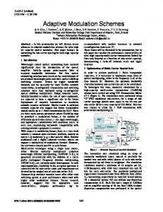
A‘ Fig. 6. Photograph of differential
should be smaller than 5. D. Smbiliry
In order
to
obtain
good
feedback amplifier.
matching
between
the
current
Since there is no dc current flowing through the transistors ikfl 8 and lkf19, gn,, and gm,, are zero and no current is fed
mirrors, Further,
back. As a result the small signal scheme of the simple OTA is obtained but with larger internal capacitance due to the gate
geometry, 2) the same neighborhood, and 3) the same orientation on the chip. Only the current mirror of the tail current source makes an exception to the last rule.
and overlap and kf14.
capacitance
of the transistors Ml 1, ilfl 2, Ml 3,
the layout was made as symmetrical as possible. all transistors of a current mirror have 1) the same
There is no static bias current
The amplifier
is designed to be stable for small capacitive
source provided
on chip; the
bias current can therefore be set externally.
loads and to have a gain of 60 dB for 1P = 1 PA. A small signal analysis shows that for a current
ratio b of unity
capacitive load of 5 pF is sufficient
a minimal
for compensation.
For
F. Experimental
Results
In order to measure the escape voltage and the total power
current ratios b larger than one, the dominant pole moves to higher frequencies so that a larger capacitive load is needed.
the configuration
When large steps are applied the nonlinearity of the amplifier becomes important. Since in nonlinear systems it no longer makes sense to speak about poles, bode diagram, settling time, etc., the stability of
and V+ - V- = 5 V, For zero Vin, only leakage currents are flowing through the amplifier. When a voltage difference is applied, those leakage currents are fed back so that the cur-
the amplifier
rent level in the amplifier
cannot be studied by using classical tools.
shown in the Appendix natural
equilibrium
pendently
It is
as a function
of the input voltage difference
of Fig. 7(a) was used.
current loUt as a function
Vi~,
The measured load
of fin is given in Fig. 8 for 1P = O
increases.
Once the escape voltage
that the system has a single point of
of about 40 mV is exceeded, the current level increases very
to which the system always returns inde-
drastically. The total supply current, as a function of fin, is represented in Fig. 9 for three different values of bias current 1P. Biased
of the input signal amplitude.
E. Layout The amplifier
consumption
is integrated
in a low voltage 5 pm CMOS
technology. The total area is 0.075 mmz, which is comparable to that of state of the art CMOS op amps, and this in spite of the fact that the adaptive biasing part takes about 20 percent of the total amplifier area. Table I shows the device dimensions and the corresponding weak inversion limits. Fig. 6
at 30 nA, the input transistors are operating in weak inversion. An input voltage difference of only 50 mV causes the total current consumption to increase to about 65 I.LA. Then the input transistors cease to operate in weak inversion so that the current will increase less than exponentially. For input signals exceeding a few hundred millivolts the total power consumpt-
The dimensions of the
ion becomes almost independent of the bias current 1P. The maximum supply current, determined by the supply voltage
transistors of the subtracter were chosen to minimize the total amplifier size. The current feedback factor A of the amplifier equals 2.
and the beta’s of the transistors, is about 300 MA. This maximum supply current determines the maximum rate of change of the output voltage.
shows a photograph
of the amplifier.
DEGRAUWE
f &
et al.: ADAPTIVE
BIASING
CMOS AMPLIFIERS
525
v+
TABLE II SMALL SIGNAL CHARACTERISTICS
I~Up
(a)
vm ~
lP=l
PA
v ~up’sv
OUT
+
Gain
IOU+
7
64 dB
Offset
3.68 mV+4mV
Noise
A“-
190 nV/@ 60 nV/@
1 kHz 10 kHz
CMRR
62 dB
PSRR V+ v_
63 dB 44 dB 0.25 V/I.M
“SR” (Cload = 470 PF) (b)
DUT
GBW [Hz]
configuration for obtaining ~~up – Tin curves. (b) Measurement configuration for determining ac characteristics.
Fig. 7. (a) Measurement
F
1P=3PA
>IP=IPA
IOU+ [PAI
IP=0.3PA
0.1--
lOOkI o
0.5
1.0
5
[Vp+-pl
vi”
Fig. 10. Measured –3 dB breakpoint as a function (unity gain feedback).
0.05..
of input amplitude
IP=O
Measured values of the most important small signal characteristics of the amplifier are listed in Table II. The negative
o 0
40
power supply rejection ratio can be improved by putting the input transistors in a separate p-well and by using an on-chip
Vin [mVl
bias current source which is independent
-0.05-
Fig. 10 shows the gain-bandwidth as a function
of the amplitude
of the supply voltage.
product
of the amplifier
of the sine wave input
signal.
The -3 dB breakpoint frequency was measured using an oscilloscope, so these figures must be interpreted carefully since
-0.1-
they include the higher harmonics of the output signal. However, one can see that the gain-bandwidth product increases
Fig. 8. Measured output current for 1P = O.
with the amplitude of the input signal up to a certain maximum. This maximum occurs when the maximum current is
‘r%~ ..
flowing 10-4,
through
rent amplifier,
the amplifier.
For a classical fixed bias cur-
the gain-bandwidth
product
decreases with in-
creasing input amplitude. IV.
DIRECT
FEEDBACK
AMPLIFIER
10+ ,
The
direct
micropower made
feedback buffer
for
so that nearly
amplifier large
the whole
is designed
capacitive supply
loads. current
to be used The
as a
design
is
is used to charge
the load capacitor.
10-6-
A. Principle Fig. 11(a) represents the scherhe of the amplifier. show the simple transconductance Fig. 9. Supply current as a function
With tion
the
amplifier
as shown
connected
in Fig. 7(b)
follower
a capacitive
pF, a slew rate of 0.25 V/IM is measured.
configuraload
of 470
For a capacitive load
of 10 pF, the slew rate is more than 10 V/I..M independent the bias current 1P.
Thick lines
discussed above.
The amplifier is split up in two symmetrical parts. Then, without making a subtraction, @ each input stage the current of one branch is directly fed back to the tail current source. When the differential input voltage ~n equals zero, the cur-
of the input signal.
in voltage
and with
amplifier
of
rents II and 12 are equal and givenby(11) lI(Z) 11
= ~ (lP +A =12
=10
(11)
“~1(2))
=IP/(2-
and (12).
A).
(12)
526
IEEE
JOURNAL
OF SOLID-STATE
t% z
CIRCUITS,
VOL.
SC-17,
NO. 3, JUNE
1982
(a)
v+
M6 F18
M2
AI1j
I
P
/11
,+ jlOAI1
I-
~
‘j!j
~7 ~9 ~N-
IOAI1
TABLE III MASK DEVICE DIMENSIONSDIRECT FEEDBACKAMPLIFIBR
poIp
]AII
llP
Ml
~_
Fig. 13. Chip photograph of direct feedback amplifier.
n
+
M13
M3 M5
Mll
Dimension
(b)
Fig. 11. (a) Direct feedback amplifier.
(b) Realized scheme.
100 x lox 50x6 300X 30X 21 x
1, 13 3,5,11 7,9 2 4 6, 8
ing two
halves.
integrated device
Fig.
,’
The of the input signal.
Stability
is ensured if the current feedback factor is smaller When Vin is larger than zero, the current 11 inthan two. creases. Due to positive feedback the current may reach a value much larger than 10 which results in a high driving capability. This is true as well for 12 when ~n is negative. Simple calculations yield that II (a) is @ven by (13) which is represented in Fig. 12 for various values of the current factor A . (b = 1)
feedback
1P 11 (2)=
~~~+
exp (- (+) fi./(n
(13)
“ VT))”
1P” (exp (~n/(n
Notice amplifier, voltage.
“ VT))-
1)
.~ (14)
1-
(A - 1) “ exp (~n/(rr
“ VT))
“
that, just as in the case of the differential this
amplifier
13 is a photograph
dimensions
and the corresponding III.
The total
also has a well-determined
of the amplifier.
as the first
It is
amplifier.
The
weak inversion
size of the amplifier
amplifier
is designed
(>100
pF).
output
stage transistors
problems. times
This
makes
C, Experimental
charge
large
limits is about
capacitive
loads
to le~gth ratio
of the
possible
without
flowing
in the output
The current
the internal
to
a large width
current
resulting
running
into
stability
stage is about
15
in a high efficiency.
Results
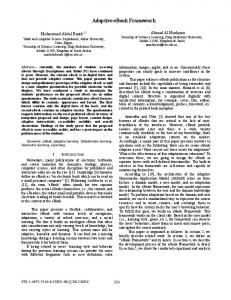
The measured supply and output current as a function of the input signal are represented in Fig. 14(a). One can see that almost the whole supply current is available at the output. The maximum output current, which is determined by the beta’s of the transistors and the supply voltage, is about 50 vA. Fig. 14(b) is a detail of Fig. 14(a) for small input signals. Biased at 2 X 10 nA, a transconductance
The available cmtput current, which equals 11-12, is ghen by (14) and is represented in dotted lines in Fig. 12 I= ‘UT
12 12 12
400 X 190 pm.
nvT
1
Fig. 12. Calculated currents as a function
200 20 200 200 20 14
12 12
in the same technology
are given in Table ,’
Weak-inversion limit B“ v; [nAl
WX 1 [~m]
Device
sured.
Under these conditions
of 20 vA/V
is mea-
and with a capacitive load of
100 pF the amplifier has a GBW of 30 kHz. The measured output current for zero 1P is shown in dotted lines in Fig. 14(b). Once the escape voltage is exceeded, the output current increases very drastically.
feedback
V.
CONCLUSIONS
escape In this paper two
amplifiers
their own bias current.
are presented which
regulate
If no signal is applied the amplifiers
B. Layout
operate at a very low current level.
Orily half of the amplifier was integrated [see Fig. 1 l(b)] since the amplifier can easily be realized by properly connect-
plied the current in the amplifiers increases so that amplifiers have a high driving capability.
Only when a signal is apthese
DEGRAUWE
et al.: ADAPTIVE
BIASING
CMOS AMPLIFIERS
50.
..------ kup ,.,., I OUt
527
V(n
I [pA]
------- . .
ancmc
-------- -- 0
-1oo
0
V. T
, ,C
100 V,n
Fig. 15. SC integrator during integrating phase.
[mV]
(a)
Fig. 16. Behavior of input of nonlinear amplifier
1
(b)
Fig. 14. Measured supply and output current versus input (b) Detail of (a) for small input signals.
signal.
havior of the integrator of differential
~ d(vo The first
amplifier
has a slew rate which is more than an
order of magnitude better than earlier presented micropower amplifiers [2], [3]. Since this amplifier is fairly small it is well suited falters.
for
the
use in large micropower
is fully described by the following
pair
equations:
If.)
-
‘ain”
dt ~.d(vo-
dfin C.— dt
(A2)
~n)+uo.c.~+~+~(vin)=o
dt
dt
sampled data
in SC integrator.
(A3)
R
where
The second amplifier
is well suited for use as a micropower f(Vin)=
buffer since it does not slew and has a high efficiency.
b . (beta . I fin 1/2 +~m)
“ fin
beta = beta of input transistor. APPENDIX
For a step input (A3) is then of the form In order ential
feedback
1) The glected 2)
to be able to study
with
work
most
“slew
R=—
‘Early
rate”
factor
dljn
can be ne-
of the output
is close to one. level,
in strong
resistance
amplifier
stage.
(This
guaran-
and results in a small size amplifier.)
current
are assumed
of the differ-
have to be made.
of the
to the time constant
of the time
The output
some assumptions constants
feedback
For an increasing
put transistors 4)
time
respect
The current
tees a sufficient 3)
amplifier
internal
the step response
the input
inversion.
to always
work
of the amplifier
transistors
Therefore, in strong
dt
_ ‘a’+a’”nn+a’
.—v& /qnl
(A4)
where al = ‘step
will
“ ‘Early
I.C1
the in-
VEarlY + b . beta
inversion.
can be modeled
by
(Al)
I+i
where I represents the dc current and i the ac current flowing
a2=-
(
I.C1
.1P
(1+CZin) “C’I)
b . beta a3=-————_ 2.C, Cl=c.
(ao+z%) through the output stage. This formula, represented in Fig. 16 has only one point An SC integrator, during the integrating phase, using a differential feedba~k amplifier ‘can be modeled by Fig. 15. The be- - where the derivate is equal to zero. This is an equilibrium
IEEE JOURNAL
528
point since for Vin larger than Veq the derivate is smaller than zero and thus the input will decrease until
Ve~ is reached.
For
Vin smaller than Veq, the derivate is larger than zero and thus the input will increase until V,q is reached. REFERENCES [1]
[2]
[3] [4] [5] [6]
[7]
[8] [9]
[10] [11]
W. Steinhagen and W. L. Engl, “Design of integrated analog CMOS circuits-A multichannel telemetry transmitter,” IEEE J. Solid-State Circuits, vol. SC-13, pp. 799-805, Dec. 1978. F. Krummenacher and J.-L. Zufferey, “High gain CMOS cascode operational amplifier,” Electron. Lett., vol. 16, pp. 232-233, Mar. 1980. F. Krummenacher, “High gain CMOS OTA for micro-power SCfilters,” EZectron. Lett., vol. 17, pp. 160-162, Feb. 1981. M. A. Copeland and J. M. Rabaey, “Dynamic amplifier for M.O.S. technology,” Electron. Lett., vol. 15, pp. 301-302, May 1979. B. J. Hosticka, “Dynamic CMOS amplifiers,” lEEE J. SolidState Circuits, vol. SC-15, pp. 887-894, Oct. 1980. F. Krummenacher, E. Vittoz, and M. Degrauwe, “Class AB Lett., vol. CMOS amplifier for micropower SC-filters,” Electron. 17, pp. 433-435, June 1981. J. Fellrath and E. Vittoz, “Small signal model of MOS transistors Modelling in weak inversion,” Proc. Journees d’Electronique, Semiconductor Devices, pp. 315-324, Oct. 1977. J. E. Solomon, “The monolithic op amp: A tutorial study,” IEEE J. Solid-State Circuits, vol. SC-9, pp. 314-332, Dec. 1974. J. E. Solomon, W. R. Davis, and P. L. Lee, “A self compensated monolithic op amp with low input current and high slew-rate, ” in ISSCC Dig, Tech. Papers, 1969, pp. 14-15. W. E. Hearn, “A fast slewing monolithic operational amplifier,” IEEE J. Solid-State Circuits, vol. SC-6, pp. 20-24, Feb. 1971. E. Vittoz and J. Fellrath, “CMOS analog integrated circuits based on weak inversion operation, ” IEEE J. Solid-State Circuits, VOL SC-12, pp. 224-231, June 1977.
Marc G. Degrauwe was born in Brussels, Belgium, on August 16, 1957. He received the E.E. degree from the Katholieke Universiteit Leuven, Herverlee, Belgium, in 1980. During the summer of 1980 he was on leave at Centre Electronique Horloger S.A., Neuch~tel, Switzerland, where he was involved in the development of micropower amplifiers. He is working towards a Ph.D. degree on micropower sample data filters. He also has an LW.O.N.L. Fellowship which allows him to work as a Research Assistant at the ESAT Laboratory, Katholieke Universiteit Leuven.
OF SOLID-STATE
CIRCUITS,
VOL. SC-17, NO. 3, JUNE 1982
Jozef Rijmenants was born in Nijlen, Belgium, on May 30, 1956. He received the electrical engineering degree from the Katholieke Universiteit Leuven, Heverlee,Belgium, in 1979. After graduation, he worked on an industrial project in the field of switched capacitor filters at ESAT Laboratories, Heverlee, Belgium. In January 1982 he joined the CAD software company Silvar-Lisco, Belgium.
Eric A. Vittoz (A’63-M’72) was born in Lausanne, Switzerland, on May 9, 1938. He received the M. S. and Ph.D. degrees in electrical engineering from the Federal Institute of Technology, Lausanne, in 1961 and 1969, respectively. After spending one year as a Research Assistant, he joined the Centre Electronique Horloger S.A., Neuch~tel, Switzerland, in 1962, where he became involved in micropower integrated circuit developments for the watch, while preparing a thesis in the same field. Since 1971 he has been Associate Director of this Laboratory, supervising advanced developments in electronic watches and other micropower systems. His field of personal research is in very low-power CMOS integrated analog circuits. He also lectures and supervises student work in integrated circuit design at the Federal Institute of Technology, Lausanne.
Hugo J. De Man (M’81) was born in Boom, Belgium, on September 19, 1940. He received the electrical engineering degree and the Ph.D. degree in applied science from the Katholieke Universiteit Leuven, Leuven, Belgium, in 1964 and 1968, respectively. In 1968 he became a Member of the Staff of the Laboratory for Physics and Electronics of Semiconductors at the University of Leuven, working on integrated circuit technology. From 1969 until 1971, he was at the Electronic Research Laboratory, University of California, Berkeley, as an ESRONASA Postdoctoral Research Fellow, working on computer-aided devices and circuit design. In 1971 he returned to the University of Leuven as a Research Associate of the Belgian National Science Foundation (NFWO). In 1974 he became a Professor at the University of Leuven. From 1974-1975, he was Visiting Associate Professor at the University of California, Berkeley. His current field of research is the design of integrated circuits and computer-aided design.