student LMC simulator projects using Borland Java ap- plets, Macromedia Director for animation, running on. MSWindows98 but no products yet.
Proceedings of the 2001 Winter Simulation Conference B. A. Peters, J. S. Smith, D. J. Medeiros, and M. W. Rohrer, eds.
A CROWD OF LITTLE MAN COMPUTERS: VISUAL COMPUTER SIMULATOR TEACHING TOOLS William Yurcik
Hugh Osborne
Department of Applied Computer Science Illinois State University Normal, IL 61790, U.S.A.
School of Computing & Mathematics University of Huddersfield Queensgate, Huddersfield, HD1 3DH, U.K.
complex to understand; and (C) cryptically documented. This makes executing laboratory experiments for students a challenge requiring extensive preparation and the result may be skills and knowledge not transferable to other machines. Third, computer architecture is intimidating to most students – while students may have a high level computer literacy of software applications, languages, and peripherals, many have incomplete, unrealistic, and sometimes profoundly strange conceptions of how a computer works underneath the cover. Thus, most students are reluctant to figuratively or literally open the computer cover for discovery, scared of the binary can-of-worms they do not understand. Lastly, students are crowded with marketing information about computers from advertisements on television, radio, and magazines. Since students are not informed consumers understanding computer architecture there are two effects: (1) empty or misleading information crowds out useful facts about computer architectures, and (2) students acquire a false sense of competence due to familiarity with computer marketing hype. All is not lost however. Recent textbooks, web resources, supplementing traditional lectures with active learning experiences, and the sharing of distributed expertise have empowered educators with new tools and increased the opportunity for student learning of computer architecture (Cassel et al. 2001; Yehezkel, Yurcik, and Pearson 2001). This paper describes the use of visual computer simulators as teaching tools for computer architecture. Detractors state that simulation is not as good as the real thing. We agree – simulation can be better than the real thing! For instance, assembly language programming can be one of the most user unfriendly human-computer interactions – a computer simulator can make assembly language programming more user friendly and even intuitive. A simulator can highlight core computer features of educational value and eliminate unnecessary details unique to a specific manufacturer. Lastly, creating a computer simulator in software is a cathartic educational experience similar to building a real computer in hardware but less costly in monetary terms,
ABSTRACT This paper describes the use of a particular type of computer simulator as a tool for teaching computer architecture. The Little Man Computer (LMC) paradigm was developed by Stuart Madnick of MIT in the 1960s and has stood the test of time as a conceptual device that helps students understand the basics of how a computer works. With the success of the LMC paradigm, LMC simulators have also proliferated. We compare and contrast the current crowd of LMC simulators highlighting visual features. We found unexpected insights since despite starting with the same paradigm with the same goals, each implementation is distinct with different strengths and weaknesses. It is our intention that interested educators will find this a useful starting point or useful reference for incorporating simulation into their courses. 1
INTRODUCTION
The value of teaching computer architecture and assembly language programming is an old debate that continues to resurface as outside pressures on educational institutions press for market-driven skills based on high-level abstraction. We feel that concrete and rigorous low-level educational experiences are necessary as a foundation before building toward higher-level abstraction. Dr. C. Ravishankar, Professor of Computer Science/University of California-Riverside says it clearly, “Information hiding is all very good, but students need to have some information before they can start hiding it.” Computer architecture is also maligned because it is a difficult topic to teach. First, a wide range of skills and details need to mastered – ranging from transistor implementation at the logic gate level up to the architecture of an entire computer system (with one measure of scope being the number of transistors under consideration ranging from a few to millions). Second, actual computer system architectures contain characteristics that are (A) unique to the manufacturer; (B)
1632
Yurcik and Osborne more flexible to allow the students to make mistakes and recover, and easily extensible allowing increasing functionality upon a core design. Simulators can be built for many different actual machine architectures or generalized/experimental machines of educational value can be created by students as projects. The Little Man Computer (LMC) simulators presented here fall under the class of a generalized/experimental machine of educational value. 2
• •
a program flow instruction (skip, branch, jump) that conditionally or unconditionally alters the value in the location counter a halt instruction (or coffee break) that halts execution of the program
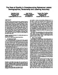
The LMC paradigm is illustrated in Figure 1.
THE LMC PARADIGM
The LMC paradigm was developed by Stuart Madnick and John Donovan of MIT during the 1960s where it was taught to all MIT undergraduate computer science students. The paradigm has stood the test of time as a conceptual device which helps students understand the basics of computer architecture. Irv Englander/Bentley College currently has a popular textbook which continues the LMC tradition (Englander 1996; Englander 2000). The LMC paradigm consists of a walled mailroom, 100 mailboxes numbered 00 through 99, a calculator, a two-digit location counter, an input basket, and an output basket. Each mailbox is designed to hold a single slip of paper upon which is written a three-digit decimal number. Note that each mailbox has a unique address and the contents of each mailbox is different from the address. The calculator can be used for input/output, temporarily store numbers, and to add and subtract. The two-digit location counter is used to increment the count each time the Little Man executes an instruction. The location counter has a reset located outside of the mailroom. Finally, there is the “Little Man” himself, depicted as a cartoon character, who performs tasks within the walled mailroom. Other than a reset switch for the location counter, the only communication an external user has with the Little Man is via slips of paper with three-digit numbers put into the input basket or retrieved from the output basket. An instruction cycle takes place as follows: • • •
Figure 1: The Little Man Computer Paradigm The analogy between LMC and real computers is not perfect. In a real computer, memory (mailboxes) are separated both physically and functionally from the central processing unit (CPU). In most computers, registers are available to hold data temporarily while it is being processed. Although the LMC paradigm has no registers, the calculator display loosely serves the purpose of an accumulator. Clock timing and interrupts are not part of the LMC paradigm. Lastly, the LMC instruction set is based on the decimal system, not binary as a real computer would be. In spite of these deviations from reality, the use of this simple but powerful model with a more familiar number system allows students to focus on understanding the tasks being performed in executing instructions rather than the sometimes complex details of a specific manufacturer’s implementation. In addition, the Postroom Computer (see section 3.1) addresses some of these points.
The Little Man looks at the counter, memorizes the number, and increments the counter by one. He retrieves an instruction from the mailbox specified by the memorized number. He then executes the instruction.
The instruction could be: • • •
3
an arithmetic instruction (add or subtract) involving use of the calculator a memory access (load or store) in which data is transferred between a mailbox and the calculator an I/O instruction (input or output) in which data is transferred between the calculator and the input or output tray
MULTIPLE LITTLE MAN COMPUTER SIMULATORS
With the success of the LMC paradigm, LMC simulators have proliferated. The current crowd of LMCs not only captures LMC information processing functionality but also use visual techniques to highlight LMC operation. The goal is to allow student visualization of different parts of the LMC simultaneously to show relationships and thus form student intuition.
1633
Yurcik and Osborne Both the fetch/execute cycle and the microcode implementation are fully specified and traceable (using the Update Plan specification formalism – see section 3.1.4), allowing explanation of these concepts to be fully integrated with the model. In the other direction, a compiler is available from a simple high level language to Postroom Computer code. It is also possible to configure the performance of the various components of the machine model to emphasize the importance of, for example, caching. Work is in progress on a simplified version of the Postroom Computer aimed at primary school children (age group 7-11).
Unexpected insights can be gained by comparing and contrasting the current crowd of LMC simulators since despite implementing the same paradigm with the same goals, each implementation is distinct with different strengths and weaknesses. We start off with an in-depth description of the most sophisticated LMC simulator and then work backward to describe less developed LMCs. Independent of sophistication, all of the LMC simulators are successful at focusing on a different aspect of educational pedagogy in teaching computer architecture. 3.1 The Postroom Computer
3.1.1 Postroom Instruction Set Extensions
The Postroom Computer is the most developed extension of the Little Man Computer model, designed to introduce aspects of computer architecture and low-level programming in an incremental way. The extensions are designed to provide a range of computing models within the LMC paradigm. As they are introduced they can be related both to the LMC paradigm and to “real” machines. The main extensions are: • • • • •
The first extension of the paradigm is the introduction of different instruction set architectures. There are four Postroom Computer instruction set architectures: 1. 2. 3.
a range of instruction set architectures – 0, 1, 2, and 3 address machines, a choice of addressing architectures – immediate or indirect, a choice of I/O architectures – (implicit) busy wait or interrupt driven, a large number of mailboxes, and hence a larger address space and a larger (multiple digit) location counter, some opcodes are different.
4.
a zero address stack-based machine a one address accumulator-based machine a two address machine, with one source operand and one destination operand a three address machine, with two source operands and one destination operand
The basic design of the instruction set is common to all machines. The opcode consists of one digit and each address field is three digits long. A word on an n address machine is 3(n+1) digits long. Note that this implies that each machine could have up to 1000 three digit opcodes, which would make it possible to introduce CISC architectures, but in didactic practice it is better to stick to the conceptually simpler one digit opcodes. There are some minor differences in the instruction sets – e.g. the zero address machine has PSH (push to stack) and POP (pop from stack) instructions, rather than LDA (load accumulator) and STA (store accumulator), while the two and three address machines use these opcodes for MOV (move value) and MEA (move effective address). The two and three address machines replace the JMP (unconditional jump) and SKP (conditional skip) instructions of the zero and one address machines with a single conditional JMP instruction, and uses the extra opcode for a MSK (logical mask) instruction.
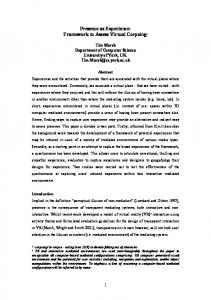
The extensions in the Postroom Computer have a high degree of orthogonality, inspired by the architecture of the PDP11. This orthogonality means that it would be more correct to speak of 16 separate Postroom Computers, rather than one Postroom Computer. The basic Postroom Computers are very similar to the original LMC, while the more advanced models bear more similarity to real architectures, in particular the PDP11. The design space of the Postroom Computers is shown in Figure 2.
3.1.2 Postroom Addressing Mode Extensions The second extension to the basic model introduces extra flexibility in addressing. In the basic model (the direct addressing model), a three digit address is simply an address in memory. In the indirect addressing model, the three digits are comprised of a one digit addressing mode and a two digit register number. The large number of registers is mostly due to the microcode implementation, which is based on a RISC architecture. There are ten user registers (general purpose
Figure 2: The Postroom Computer Design Space
1634
Yurcik and Osborne and to cache, main and background memory, and for basic I/O operations. Program execution can be traced. The simplest trace will show the source-code line currently being executed. A more detailed trace is available showing state changes in the machine model. These are expressed using Update Plans: a formal, yet intuitively clear, specification language for low level activities (Osborne 1992; Osborne 1994; Osborne 1996). Yet more detailed traces are available, describing execution at the fetch/execute level and microcode level. The fetch/execute cycle and microcode are also fully specified in Update Plans. Files of the traces can also be produced for inspection after execution has terminated. Execution may be in burst mode, in which instructions are executed until a HLT (halt execution) instruction is reached, or step mode, in which execution steps through the program one “program unit” at a time. The user may specify the level of the “program unit” to be a single Postroom Computer instruction, a single phase of the fetch/execute cycle, or a single microcode instruction. There is a mechanism using annotation of the source code that allows the user to set Postroom Computer instruction level breakpoints. The step level is independent of the trace level, i.e. the user may, for example, step through the program one Postroom Computer instruction at a time, while tracing execution at the fetch/execute cycle level. A compiler is available for a simple imperative language with if, while, repeat and case statements, primitive and compound types (both standard and user defined), and procedures. The compiler provides lexical and syntactic checking, and type checking in which the user can choose the degree of polymorphism and implicit coercion. Compilation is by stepwise program transformation, and each step in the transformation can be inspected by the user, and used for teaching purposes. Currently no attempt is made to optimize the resultant Postroom Computer code. A useful exercise for students is to give them the unoptimized code produced by the compiler with the challenge to make it as (space and/or time) efficient as possible.
registers) and 20 “administrative” registers – program counter, stack pointer, flag register, MAR, MDR, I/O buffer registers etc. The ten addressing modes are: • • • • •
register direct and indirect immediate direct and indirect base direct and indirect predecrement direct and indirect postincrement direct and indirect
3.1.3 Postroom Input/Output Extensions The third dimension in the design space is provided by the Postroom Computer's I/O model. In the basic Postroom Computer an I/O instruction ( INP [input] or OUT [output]) is executed, just like any other instruction, as an atomic action – i.e., execution of the program is suspended until the input or output is complete. This is implicitly a form of busy wait I/O. In the interrupt driven I/O model an I/O instruction will cause an interrupt. An interrupt handler must be provided that traps the interrupt and passes the necessary data to the I/O module that will perform the required action. Upon completion of the I/O, the I/O module will cause another interrupt, which must again be trapped by the interrupt handler. 3.1.4 Building a General-Purpose Computer System Based on the Postroom Computer The Postroom Computer system allows the user to assemble, load and trace execution of Postroom Computer programs. A compiler from a simple high level language to Postroom Computer assembler is provided. Different speeds of Postroom Computer components can also be modeled. The Postroom Computer Assembler offers all the usual features of an assembler: lexical and syntactic check, symbolic labels, and mnemonics for opcodes, registers, addressing modes and condition codes. Both integer and character data values are supported, and strings are converted to sequences of characters. There is also a macro mechanism, including macro parameters, allowing users to program their own macros, e.g. a MUL x y macro for multiplication. Intermediate files are produced at each stage of assembly, and may be preserved for inspection, and for illustration of assembly processes – e.g. macro expansion, label generation – to the students. The loader will load a Postroom Computer machine code file and start execution. Upon completion of the program it will report the number of instructions executed, and may be configured to also report the (virtual) time required for execution. More advanced configuration options allow the user to model differing levels of efficiency for the various components of the Postroom Computer, defining the (virtual) time taken for, for example, access to registers,
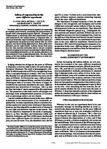
3.2 Web-Based LMC-1 Under the direction of Professors Larry Brumbaugh and William Yurcik of Illinois State University (Yurcik and Brumbaugh 2001; Yurcik, Vila, and Brumbaugh 2000), an interactive LMC simulator (see Figure 3) was developed so that students could visualize simultaneous events occurring during the execution of their LMC assembly language programs. Word of this intuitive visualization spread such that the application was eventually ported to a web-based application implemented in Java embedded within an applet to provide ubiquitous Internet access. The only user requirement is a Java-enabled browser such as Internet Ex-
1635
Yurcik and Osborne plorer 4.0 or Netscape Navigator 3.0. Unique features to this web-based LMC-1 simulator include: • • •
• • • • •
an LMC assembly code editor with instruction syntax checking a one-pass assembler to visualize the mnemonic assembly language to machine code conversion program status field which displays current status of LMC operation including error messages and flags (flags based on current calculator value if positive, negative, zero, and error - working on overflow) a visualization of the load process from machine code to mailbox address/contents a halt operation for run-away programs different execution modes including step into (single step), burst mode, step-over (goes through conditional logic) location counter reset LMC assembly language program input/output to local file system allowing programs to be saved and loaded from local platform with security based on Certificate Authority authentication
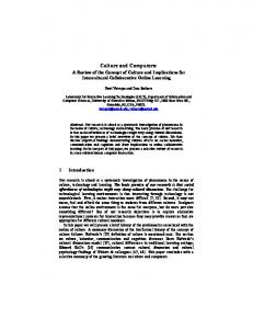
Figure 4: An ActiveX Web-Based LMC-2 Simulator 3.4 Son-of-LMC Alan Pinck of Algonquin College Canada has developed a Son-of-LMC simulator running under Windows 95/98. Son-of-LMC was developed in Visual Basic (v.4) and Dynamic Link Libraries are provided. Unique to Son-ofLMC is visualization of the bootstrap process, subroutine calls, and the linking process. See Figure 5.
Figure 3: A Java Web-Based LMC-1 Simulator 3.3 Web-Based LMC-2 Satyanarayana Seethasridhar, under the direction of Professor M. Dadashzadeh of Wichita State University, has developed a web-based ActiveX LMC-2 simulator, which runs on Internet Explorer (preferred) or Netscape Navigator. This simulator does not attempt to visualize the fetchexecute cycle but does visualize the calculator, input/output boxes, location counter, and memory in a simple and intuitive interface. There is no documentation provided but software developer contacts are linked. The Initial screen of the simulator is shown in Figure 4.
Figure 5: The Son-of-LMC Simulator
1636
Yurcik and Osborne 3.5 Shockwave LMC
3.7 LMCs in Progress
A team at the University of Hertfordshire has developed a shockwave animation visualization (browser plug-in) of the LMC paradigm to “test” students understanding of the paths he takes “in his day-to-day routine”. They report that students gain a fuller understanding of the fetch/execute cycle by visualizing the individual components and their interactions. The “Introduction” page of the Shockwave LMC is Shown in Figure 6.
Kath Garnet of DeMontfort University U.K. has proposed student LMC simulator projects using Borland Java applets, Macromedia Director for animation, running on MSWindows98 but no products yet. 4
LMC SIMULATORS IN THE CLASSROOM
LMC simulators serve as a first introduction to computer architectures. The paradigm is introduced and related to specific instruction set implementations and visualization of the fetch/execute cycle. The Postroom 0, 1, 2 and 3 address machines allow a discussion of the different architectures and their advantages and disadvantages – e.g., instruction complexity against program complexity. The zero instruction machine in particular can serve as an introduction to the concept of the stack. Indirect addressing increases the flexibility of the model. This is related to the basic LMC model by describing the main memory as being in a separate storeroom with a corresponding longer access time (see Figure 7). Students are introduced to the concept of a memory hierarchy, and are encouraged to use the loader's timing mechanism to compare the efficiency of indirect and direct addressed programs
Figure 6: The Shockwave LMC Information Display 3.6 LMC Documentation There are three main websites for LMC simulator documentation in addition to the Englander text: •
•
•
Web-based LMC-1 has a brief description of the LMC paradigm in addition to simulator specific details so users can do just-in-time reference while LMC assembly programming. Hugh Osborne has extensive documentation of various versions of LMC, comparable to a living textbook since it is modified frequently, more LMC material here than in the Englander textbook. Professors Susan Riedel and Jeffrey Hock of Marquette University have created a LMC Documentation and User’s Guide. Originally prepared in January 1994 and revised in August 1994 (current is version 3.5). Much of the LMC software found here is written by the author’s students to satisfy course requirements in software design or special projects.
Figure 7: LMC with a Main Memory Storeroom The need for interrupt driven I/O is again explained in terms of efficiency, comparing the speed of typical CPUs to that of typical I/O devices, including human beings. The model is again expanded with a background memory mod-
1637
Yurcik and Osborne eled as being in a warehouse at some distance from the postroom (see Figure 8) and direct memory access is discussed.
• • • • • • • •
The ultimate aim: to provide a computer architecture/low level programming paradigm that can take students from their first elementary school introduction to “how do computers work?” through first year undergraduate Computer Systems Architecture 101, to more advanced undergraduate modules on compiler construction, advanced architectures and networks. Ideally a future LMC could be formally specified using Update Plans giving not only a “megaLMC” but also the first, as far as the authors are aware, example of a system fully specified and validated from high level code/operating system down to logic gates.
Figure 8: LMC Background Memory Warehouse Model The fully specified and traceable fetch/execute cycle and microcode levels enable these concepts to be related directly to the LMC model. The microcode implementation is based on RISC architectures and although its implementation is currently sequential, it will in future be pipelined providing a Postroom Computer example of this type of architecture. The flexibility of different LMC implementations makes a large range of realistic programming exercises possible. Students have in the past successfully undertaken the following exercises: • • • 5
6
implementing double word and floating point arithmetic programming a simple stack based arithmetic calculator, including variable storage and retrieval writing an interrupt handler for basic I/O actions
Predicting the future is always problematic but we attempt some educated guesses on subsequent LMC simulator developments. Combining the intuitive user interface design of web-based Java LMC-1 with the more developed underlying processing capabilities of the Postroom computer would be the LMC simulator state-of-the-art circa 2001. A wish list for extensions to the 2001 state-of-the-art include:
• •
SUMMARY
This paper summarizes the use of a LMC simulator as a visual tool to teach computer architecture. We emphasized that there is a crowd of different LMC simulators and we described and compared the LMC simulators known to the authors. We actively encourage other LMC developers to contact us so that the crowd is complete but we realize this may be a never-ending task. Thus this paper is snapshot in time of the current evolution of a long-lived and successful teaching paradigm that shows survivability into the foreseeable future. The authors also encourage anyone with knowledge of related computer simulator projects to contact them.
FUTURE LMC SIMULATOR DEVELOPMENTS
•
make it possible to switch off integer I/O so that students have to provide I/O routines for input and output of numbers as character strings complete the “pcc” (Postroom Computer Compiler) provide a basic operating system for the LMC (written in pcc?) implement basic TCP/IP protocols for LMC visually show microcode flow underneath each LMC assembly instructions introduce pipelining in microcode extend the tracing abilities to show execution at the logic gate level (in the binary machine) a “kiddies version” LMC simulator aimed at late elementary school/high school students
ACKNOWLEDGMENTS The first author would like to thank Larry Brumbaugh and Rahul Gedupudi who contributed insights into developing computer simulators and in many ways helped stir up the current crowd of LMC simulators. The second author would like to thank the University of Huddersfield for the Teaching Fellowship funding provided in 1999/2000 for the development of the Postroom Computer.
addition of a 4th dimension to the design model: binary to decimal extend the I/O module to allow multiple devices to be attached extend the I/O module for DMA
1638
Yurcik and Osborne REFERENCES Cassel, L., D. Kumar, K. Boulding, J. Davies, M. Holliday, J. Impagliazzo, M. Pearson, G. S. Wolffe, and W. Yurcik. 2001. Distributed Expertise for Teaching Computer Organization and Architecture. ITiCSE Working Group Report, [to appear] ACM SIGCSE Bulletin]. Englander, I. 1996. The Architecture of Hardware and Systems Software. John Wiley & Sons, first edition. Englander, I. 2000. The Architecture of Hardware and Systems Software. John Wiley & Sons, second edition. Osborne, H. 1994. Update Plans. In Proceedings of the 25th Hawaii International Conference on System Sciences, IEEE Computer Society Press: 488-496. Osborne, H. 1992. Update Plans – A High Level Low Level Specification Language. PhD. Thesis, University of Nijmegen, Toernooiveld 1, Nijmegen, The Netherlands. Osborne, H. 1992. Update Plans for Parallel Architectures. In Abstract Machine Models for Parallel and Distributed Computing (Proceedings of the Third Abstract Machines Workshop, Amsterdam), IOS Press. Yehezkel, C., W. Yurcik, and M. Pearson. 2001. Teaching Computer Architecture with a Computer-Aided Learning Environment: State-of-the-Art Simulators. In Proceedings of International Conference on Simulation and Multimedia in Engineering Education (ICSEE), Society for Computer Simulation Press. W. Yurcik, and L. Brumbaugh. 2001. A Web-Based Little Man Computer Simulator. In Proceedings of the 32nd ACM SIGCSE Technical Symposium on Computer Science Education, ACM Press: 204-208. W. Yurcik, J. Vila and L. Brumbaugh. 2000. An Interactive Web-Based Simulation of a General Computer Architecture. In Proceedings of IEEE International Conference on Engineering and Computer Education (ICECE), IEEE Press. AUTHOR BIOGRAPHIES WILLIAM YURCIK is an Assistant Professor of Applied Computer Science at Illinois State University. His research interests are system survivability and simulation education. He is a member of ACM, IEEE, SCS, and is the creator of the Simulation Education Homepage. His Email address is . HUGH OSBORNE is a Senior Lecturer of Computer Science at University of Huddersfield. His research interests are in formal methods and specification systems. He is a member of NVTI (Nederlandse Vereniging voor Theoretische Informatica: The Dutch Association for Theoretical Computer Science). His email address is .
1639