Students taking introductory courses in computer ..... simple. The basic LMC instruction set allows both arrays and linked lists to be created. An array is uniquely.
A Web-Based Little Man Computer Simulator William Yurcik Larry Brumbaugh Department of Applied Computer Science Illinois State University Normal, IL 61790-5t50 USA {wjyurci, Ijbrumb} @ilstu,edu Abstract This paper describes a web-based simulation tool which can be used to teach introductory computer organization based on the conceptual paradigm of a Little Man Computer. Specifically we share examples how this tool can be used to improve student comprehension of the interaction between computer architecture, assembly language, and the operating system.
1 Introduction Students taking introductory courses in computer organization and assembly language often find fundamental concepts difficult to comprehend. With this in mind we have developed a tool that represents a working model of a general computer. There are other computer system simulators, as documented in [2,4], but we believe our simulator is unique in that it is focused on beginning students while providing flexibility and extensibility to more advanced topics. Our simulation tool is based on the Little Man Computer (LMC) Model first introduced by Stuart Madnick of MIT in 1965 and further developed by Irv Englander of Bentley College in a popular computer organization textbook [1]. We have found this model operates in a manner very similar to actual computers, helping students to understand the basics of internal computer operations.
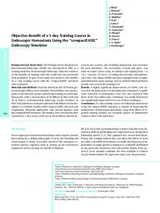
2 The Little Man Computer Architectural Model The LMC paradigm consists of a walled mailroom, 100 mailboxes numbered 00 through 99, a calculator, a twodigit location counter, an input basket, and an output basket. Each mailbox is designed to hold a single slip of paper upon which is written a three-digit decimal number. Note that each mailbox has a unique address and the contents of each mailbox is different from the address. The calculator can be used for input/output, temporarily store numbers, and to add and subtract. The two-digit location counter is used to increment the count each time the Little Man executes an instruction. The location counter has a reset located outside of the mailroom. Finally there is the "Little Man" himself, depicted as a cartoon character, who performs tasks within the walled mailroom. Other than the reset switch for the location counter, the only communication a user has with the Little Man is via slips of paper with three-digit numbers put into the input basket or retrieved from the output basket. FIGURE I THE LITTLE M A N COMPUTER PARADIGM Waged Magroom
Liltle
B
Our LMC simulation was developed using Java and has been made available on the web (http://www.acs.ilstu.edu/faculty/javila/imc/) along with comprehensive on-line documentation. We have received feedback from users (teachers and students) worldwide and welcome positive criticism to help continue improvement of this tool [5]. Permission to make digital or hard copies of all or part of this work for personal or classroom use is granted without fee provided that copies are not made or distributed for profit or commercial advantage and that copies bear this notice and the full citation on the first page, To copy otherwise, to republish, to post on servers or to redistribute to lists, requires prior specific permission and/or a fee. SIGCSE 2001 2/01 Charlotte, NC, USA © 2001 A C M ISBN 1 - 5 8 1 1 3 - 3 2 9 - 4 / 0 1 / 0 0 0 2 . - $ 5 . 0 0
It should be observed that the LMC is a direct implementation of a yon Neumann architecture. The calculator corresponds to the ALU, mailboxes correspond
204
to memory, the location counter corresponds to the PC, the I/O corresponds to input/output baskets, and the Little Man himself corresponds to the control unit. Both data and instructions are stored in the mailboxes. There is no distinction between data and instructions except when a specific operation is taking place. It is important for students to visualize the exact steps performed by the Little Man because they reflect the steps performed in a real CPU when executing an instruction. It should also be noted that the analogy is not perfect. In a real computer, memory (mailboxes) is actually separated both physically and functionally from the central processing unit (CPU). In a most computers, generalpurpose registers (accumulators) are available to temporarily hold data being processed. In LMC, the calculator display panel loosely serves the purpose of an aceurnulator. The path of Little Man performing tasks is loosely equivalent to computer bus connections but does not allow for data to be on different buses simultaneously (Little Man can not be in two places at once). Clock timing and interrupts are not part of the LMC paradigm. Lastly, the LMC instruction set is based on the decimal system and a real CPU operates in binary. We make this numbering system trade-off to simplify understanding of computer architecture while rigorously covering binary/octal/ hexadecimal representations elsewhere in the course.
3 LMC Instruction Set The Little Man performs tasks by following simple instructions which are described by three-digit numbers. The LMC instruction set is fundamentally similar to the instruction sets of many different computers. In fact, the LMC instructions - data movement, arithmetic, and branching - are central to the instruction set of every computer. In a LMC instruction, the first digit describes the operation (opcode) and the last two digits specify the mailbox address to be acted upon (operand). The instructions provide a way to move data between the inbox, outbox, calculator, and mailboxes. There are also instructions that cause Little Man to stop (HALT) and branch conditionally(SKiP)/unconditionally (JUMP).
SKIP 800
SKN - skip next line if calculator value is negative
SKN
801
SKZ - skip next line if calculator value is zero
SKZ
802
SKI' - skip next line if calculator is positive
SKP
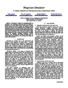
4 The Little Man Computer Simulator LMC was developed using Java JDK1.2 and is embedded in an applet so as to provide ubiquitous access to users over the Internet without the need for JDK1.2 to be installed locally. Another advantage of using this approach is that the applet is loaded in a separate window allowing the user to run the application as well as look at the HTML documentation in other windows. To enable control o f the LMC simulation, multiple threads were implemented: one thread for executing the program and a second thread listening for a user interrupt to halt the program. FIGURE II TIIELrrrLEMANCOMPUTERSIMULATOR
The LMC simulator has components:
LMC INSTRUCTIONSET Description
Mnemonic
1
LOAD contents of mailbox address into calculator
LDA XX
2
STORE contents of calculator into mailbox address
STA XX
3
ADD contents of mailbox address to calculator
ADD XX
4
SUBtract mailbox address contents from calculator
SUB XX
500 600 700
INPUT value from inbox into calculator
IN
OUTPUT value from calculator into outbox
OUT
HALT - LMC stops (coffee break)
HLT
JMP XX
NOTE: XX represents a two-digit mailbox address
TABLE I opcoae
J U M P - goto address
9
the
following two
main
•
An editor where the user can write programs and save/retrieve them
•
An
single-step assembler that translates assembly language to machine code.
Our LMC simulation visually shows a one-pass assembly process (mnemonic assembler source code to machine code) and load process (moving machine code into mailboxes). In the edit mode users can write source code (which is automatically checked for syntax errors) or load source code from an existing file. For the programmer's convenience, three different execution modes are provided: (1) Burst Mode, where all instructions in the program are executed until a HALT instruction is encountered or an abend occurs; (2) Step Into, which executes one instruction
205
at a time; and (3) Step Over, which is similar to Step Into except for SKIP instructions. For SKIP instructions, if the condition is met the program executes the next instruction and then waits for user interaction. Debugging break points can be set for all three execution modes. A flag register indicates error conditions and is set/reset for corresponding overflow/underflow conditions and zero/negative/positive values within the calculator.
5
same data is accessed as executable instructions. The LMC editor holds the Loader program. The application program and all its data are placed in the Input. Optionally, the editor can contain both programs and the Loader could transfer the application to a different location in memory. As an extension o f this, when an application finishes it transfers control back to the Loader which loads a second (or several) application(s) into memory. In addition, the present program can occupy the same memory locations formerly used by the previous program. A stream o f programs can be executed in this manner. The only limitation is the size of the Input. The Loader program provides a good working example that illustrates several basic operating system concepts.
Using LMC in the Classroom
Most students taking the computer organization and architecture course have not programmed in an assembler language. All their coding experience is in a high level language (C, C++, Java, etc.). Hence, some class time (usually one period) is spent describing and illustrating basic assembler language programming with LMC. The LMC equivalents of high level language instructions such as looping, IF-THEN-ELSE and I/O operations are identified. Some o f the most common syntax and logic errors that occur with LMC programming are described.
5.2 Addressing Modes Addressing modes provide a programmer with additional flexibility and convenience without significantly altering the fundamental simplicity o f LMC. The Madaick LMC paradigm is limited to direct, absolute addressing but we have extended our LMC simulation to include other addressing modes. Students fred these addressing modes allow them to understand how data structures such as arrays and linked lists using pointers (learned in previous algorithm courses) can be implemented. The current implementation of LMC supports four types o f addressing. Here c(address) means the value stored at the location.
Following this, if a computer lab is available, it is worthwhile to let the students write several small programs, which they enter and run. Several larger sample programs are placed on a server and students copy them. The students make simple modifications and additions to the programs and then try to successfully run them. Students quickly become familiar with providing Input, using the LMC editor to enter their code, stepping through a program and working with the various LMC controls.
AbsoluteAddressing IndirectAddressing (a pointer) ImmediateAddressing RelativeAddressing
5.1 ProgrammingAssignments Writing a program that performs integer multiplication and division illustrates how significant processing can be done using only the basic LMC instructions. It also shows how difficult this can be and the convenience of having actual multiplication and division instructions available. Multiplication is implemented using repeated addition. To calculate A ' B , add A to itself a total o f B times, or add B to itself A times. To improve efficiency, some students preface their addition by determining the smaller input value (say A) and calculate B+B+B ... +13. Compare the calculation o f 479*0 and 0*479. Division is performed using repeated subtraction and both a quotient and remainder are calculated.
ADD 95 ADD *95 where ADD #95 ADD t95
e(95)+e(Ace)..->e(Aee) c(X)+e(Ace).->e(Aee) e(95)=X 95+e(Aee)->e(Aee) c(c(Pc)+95)+e(Aee)--~c(Aec)
Absolute addressing uses the LMC mailbox directly without performing any calculations or conversions with it. With indirect addressing the address included with the instruction identifies the actual address that the instruction will use. The value at the instruction address is an address (pointer) rather than a 'data' value. With immediate addressing, the data value is stored inside the instruction and no additional memory location is accessed. Immediate addressing allows faster execution and can be a considerable convenience to the programmer when incrementing or decrementing a counter or to clear a memory location. Immediate addressing is used in the code on the left below and its absolute address counterpart is shown on the right.
A Loader program processes 'user' programs as input. The Loader program reads an application program from the LMC Input and stores it in an unoccupied portion o f memory. After the Loader copies the entire program into memory, it transfers control to the initial statement in the loaded program and it starts executing.
ADD #1 SUB #1 orADD #-1 LDA #0
This is an excellent illustration o f the yon Neumann architecture showing that both data and executing instructions are stored in memory. Initially, the Loader processes the application program as 'data'. Later, the
ADD 90 ~- incrementby 1 SUB 90