The station table uniquely defines the different instruments used through time within the GVDA. As instruments fail ..... REFERENCES. Abercrombie, R. E. (1997).
2.2
DOWNHOLE DATA DICTIONARY AND DATA FORMATTING REQUIREMENTS
J. STEIDL University of Cailfornia, Santa Barbara
ABSTRACT To improve understanding of ground motions from large damaging earthquakes and the behavior of soil at large strain levels, downhole data are critical to engineering seismologists and geotechnical earthquake engineers . In order to make any geotechnical database as useful as possible, an interface is needed which links the downhole ground motion time histories to the geotechnical information from the location where the ground motions were recorded, and/or from sites with similar geotechnical properties. While the details of how these links work and how/where the data are stored need to be worked out, the more general question of what exactly needs to be included in any downhole database should be formulated. This report lists some of the current metadata and data formats that are associated with downhole data. The idea is to use the information provided here as a starting point to developing consensus standards on how to archive and ultimately disseminate this important dataset. WHY DOWNHOLE DATA? Borehole instrumentation provides a unique opportunity to directly measure the effects of surface geology. While we must still rely primarily on surface observations of ground motion due to the high cost of drilling and borehole instrumentation, borehole observations provide critical constraints for our methods of interpreting surface observations. Borehole measurements have provided some of the most provocative results on basic seismological and earthquake engineering problems. For example borehole measurements provided direct in situ evidence of nonlinearity [e.g., Seed and Idriss, 1970; Zeghal and Elgamal, 1994; Iai et al. 1995; Sato et al., 1996; Wen et al., 1994; Aguirre and Irikura, 1997; Archuleta, 1998]; they have invited a reevaluation of the use of surface rock recordings as input motion to soil columns [Steidl et al. 1996, Boore and Joyner 1997; Archuleta and Steidl, 1998]; and they have provided basic information about scaling properties of the spectra of earthquakes of different magnitudes [e.g., Abercrombie, 1997; Kinoshita, 1992]. Clearly direct evidence of the magnitude and effect of nonlinearity of the soil response, the amplification and attenuation of seismic waves, the effects of smooth versus discontinuous variation of material properties, and the effects of water saturated versus dry soil conditions all depend on in situ borehole measurements at varying depths within the soil column. “An important factor in understanding and estimating local soil effects on ground motions and soil-structure interaction effects on structural response is the three dimensional nature of earthquake waves. ....For these purposes it is necessary to have available records of the motion at various points on the ground surface, along two mutually orthogonal directions, as well as at different depths.” 169
Invited Workshop on Archiving and Web Dissemination of Geotechnical Data
Data Dictionary and Data Formatting Standards
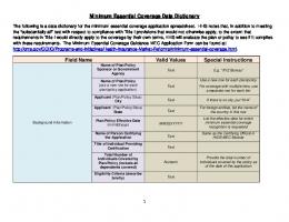
These words, published in the proceedings of the 1981 U.S. National Workshop on Strong-Motion Earthquake Instrumentation in Santa Barbara, California [Iwan, 1981], are echoed in every important meeting where policies and priorities have been set regarding strong motion monitoring. Earthquake engineers and seismologists alike agree: borehole array data continue to be a priority for better understanding of site response and soil-structure interaction issues. The measurements described in the quote above are the purpose of “Borehole Arrays.” These dense arrays of accelerometers and/or seismometers directly measure site response and ground motion variability over small distances. GEOTECHNICAL AND EARTHQUAKE ENGINEERING DATABASE NEEDS Clearly, a geotechnical database would be extremely benificial for a number of agency or disciplines. A list of possible participants and/or funding agencies that would have an interest in supporting the creation of a geotechnical and earthquake engineering database is shown in Fig. 1. This new database could expand on what has already been one of the most successful COSMOS endeavors, the COSMOS Virtual Data Center (VDC). While the current COSMOS VDC includes only ground motion time histories and associated parameters, there is a need to integrate this ground motion data with both field and laboratory site characterization data. In addition to the field and laboratory site characterization data, another database that is critical for the geotechnical earthquake engineer is the ground motion recordings from earthquakes recorded on vertical arrays of downhole instruments. These arrays sample the soil column from the surface down to the bedrock or engineering rock (linear behavior) at the base of the soil column. The most common form of the downhole data is acceleration time histories from strong motion sensors, however there are a few sites that also record pore pressure time histories using downhole transducers. This downhole acceleration and pore pressure data are needed in the validation and improved understanding of dynamic soil behavior under large strains in both saturated and dry conditions. The future emphasis on structural arrays in the Advanced National Seismic System (ANSS) and the on performance based design in the structural engineering community would suggest the need for a database where structural engineers could get time history data from instrumented buildings. Along with the time histories, the structural blue prints of the building and the locations of the instruments that recorded the building motion during the earthquake could also be available in this structural array database. The different databases mentioned above could each be a distinct database or could be contained as part of a larger VDC that included the current COSMOS VDC, the geotechnical data, the downhole array data, and the structural array data, all in one comprehensive data center. The integration of these different but related data sets is what is critical, how it is handled is secondary. This integration could be part of a significant Internet Technology Research (ITR) proposal that would deal with the details of how these different datasets were linked to one another to make them appear as a seamless data center. The data dictionary and formatting issues related to the earthquake time history data are addressed in this document, with an emphasis on the downhole data as it is closely related to the geotechnical discipline. Ultimately the goal would be a comprehensive Geotechnical and Earthquake Engineering Database. In the mean time, individual agency needs require that progress be made on individual components 170
Invited Workshop on Archiving and Web Dissemination of Geotechnical Data
Data Dictionary and Data Formatting Standards
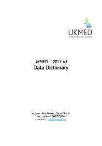
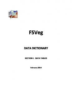
of the broader database. With this in mind, the downhole data dictionary and formatting issues are discussed here and examples provided from two existing databases, a vertical array database of the Garner Valley Downhole Array (GVDA) on an Oracle 8 database and web server platform, and the COSMOS VDC which runs the Microsoft SQL server 2000 and web server platform. THE GARNER VALLEY DOWNHOLE ARRAY DATABASE Background The Garner Valley Downhole Array (GVDA) is an engineering seismology test site that provides insitu earthquake recordings in a shallow saturated alluvial environment, which overlies weathered granite and crystalline granite of the Southern California Peninsular Ranges Batholith. Acceleration and pore pressure sensors are located at multiple levels within the soil and weathered rock profile, with the deepest sensors in the crystalline bedrock at a depth of 0.5km. These data are the control for the validation of soil dynamics wave propagation codes. While the GVDA is not the only engineering seismology test site, it is, to my knowledge, the only downhole array for which a relational database management system has been implemented to access the data. When the GVDA database was designed, it was not made with the thought of including any other array sites. It is therefore only a part of what is really needed to fully implement a relational downhole array database for multiple sites. It should be viewed as a preliminary attempt at a downhole array database. An example of the GVDA database WWW interface is shown in Fig. 2, where a simple search page gives database users the ability to pull time histories from the GVDA data set. More advanced searches can be preformed on the database using SQL queries. The database was constructed in order to give local UCSB users and users from the funding agencies access to waveforms from the GVDA experiment. GVDA Data Dictionary The GVDA database consists of five tables used to represent the time histories recorded on the experiment. Figure 3 shows these tables and the primary and foreign key relationships between each table. The information used to represent the time histories is given in detail in Appendix A and can be broken down briefly as follows: Event Table
This table gives the information associated with the earthquakes that generated the time histories represented in the database. The basic entries are event code (Primary Key:PK), date, time, location, and magnitude. The event code is a combination of the date and time (down to the ms) from an earthquake that can uniquely define the earthquake within the database. Currently there are 1162 events in the GVDA database. Station Table
The station table uniquely defines the different instruments used through time within the GVDA. As instruments fail and are replaced over time, the station table keeps track of these changes. The entries in the station table consist of a unique station name (PK), depth, type, install date, removal date, geology, location, and comments. 171
Invited Workshop on Archiving and Web Dissemination of Geotechnical Data
Data Dictionary and Data Formatting Standards
Channel Table
This table contains information on each data channel for the entire Garner Valley array. Some of the information is specific to the Garner Valley recording system such as the channel name (PK), A/D channel number, SAC channel number, and SEGY channel number. Other general fields are station name (foreign key, FK), gain, sensitivity, serial number, natural frequency, damping, component azimuth and inclination, and comments. Trace Table
The trace table contains all the information about the time history trace itself. It’s primary key is the filename associated with the actual data storage location. Other fields include the associated event code (FK), the associated channel name (FK), number of data points, sample rate, min and max values, distance and directional measures to the earthquake source, and trigger time. Error Table
A simple error table that has an error flag index as its primary key and an associated error message. This flag is linked to the Trace and Channel tables and relates comment information about bad channels/ traces for a particular event. If a sensor has a component that has gone bad for a particular event, this information is passed on to the user through the error message. THE COSMOS VDC STRONG-MOTION DATABASE Background The creation of the COSMOS VDC responds to the need in the broad strong-motion data user community for efficient access to the significantly growing increase in data from a large number of regional, state, federal and international agencies and organizations. The VDC is operated under the umbrella of the COSMOS organization [COSMOS, 2001]. The VDC provides a very cost-effective way to leverage the data processing and management resources of each of the participating agencies and organizations, by providing a single Web location from which the user can quickly and efficiently retrieve data from each of the different data sources, determined by the users own needs. Cost effective access requires customizable selection mechanisms: cross-referencing among different earthquakes, access at the individual accelerogram level, indexing for particular attributes of the data, and a number of other features offered by state-of-the art relational databases. The VDC continually develops, updates, and maintains a sophisticated parameter metadata environment, which permits the user to interactively query, search, retrieve and analyze strong-motion information using the latest developments in Web technology. At the same time, the accelerogram data and other data products are stored and maintained either by the collecting organization, or by the VDC, if the collecting organization so chooses, but in such a way as to be transparent to the user, thus the ‘virtual’ nature of the portal to the data provided by the VDC. The direct responsibility for data collection, processing, basic quality control, and storage remains primarily in the hands of the collecting agencies and organizations. The user can thus have confidence that the accelerograms and other data products are the most current available. This approach to managing a data
172
Invited Workshop on Archiving and Web Dissemination of Geotechnical Data
Data Dictionary and Data Formatting Standards
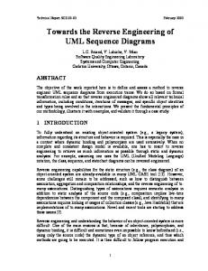
center is especially economical, while at the same time providing a major step forward in improving accessibility of the data to the research, practicing, and emergency response communities for purposes of earthquake hazard mitigation. A prototype for the COSMOS VDC was first developed at UCSB within the framework of the Southern California Earthquake Center (SCEC) activities. Expanding upon that prototype, with enhancements for ease of use, accessibility and record keeping, a virtual data center was developed as part of the COSMOS mission. The data center includes a strong-motion database that is accessible over the WorldWide Web, allowing the data to be downloaded over the Internet based on criteria supplied by the user. The Home Page is shown in Fig. 4. The VDC includes the following basic features: n
True relational database with earthquake, station, instrument, network, and accelerogram parameters;
n
Data retrieved from agencies’ existing FTP and Web sites;
n
Effective and efficient access for data users;
n
Effective feedback from users about the database, Web site, and the data itself;
n
Preservation of ownership and quality control for agencies collecting the data; and
n
Appropriate credit for participating strong-motion networks source databases.
VDC is not another data repository. Rather it is a linking of data repositories to form a virtual data center. The VDC is ‘virtual’ in the sense that it acts as a portal to the strong-motion operators or data collecting organizations. The original data (whenever possible) continue to reside at the agencies that collected and processed the strong-motion records. The searches through parameters (metadata) of all records result in pointers to the ftp sites of these agencies. Then by simply clicking on these ftp links, a user retrieves the records directly from the computers of agencies that are responsible for data collection. This procedure has many advantages: n
the integrity of the original data is preserved;
n
the agencies receive proper credit for their data collection and processing efforts;
n
users have access to updated and corrected information provided by all of the agencies; and
n
the agencies can monitor the access to their data.
Users of the database are able to access data based on a wide range of parameters, such as peak ground acceleration, response spectral ordinates, epicentral distance, earthquake name or location, site geology, housing structure, network name, station owner, or earthquake source parameters, such as magnitude, seismic moment, or focal mechanism. Users can access the database using many different methods that include a basic search, advanced search and graphical links to improve the effectiveness and efficiency for the user. 173
Invited Workshop on Archiving and Web Dissemination of Geotechnical Data
Data Dictionary and Data Formatting Standards
To date the database has been populated primarily with data from the USGS, CDMG, ACOE, and USBR networks, and the older Caltech “blue book” data, to which has recently been added data from other networks, such as the Kik-Net and K-Net Networks in Japan. As of 12 September 2001 the database contains 11,537 accelerograms recorded at 1744 stations from 199 earthquakes. Ninety-two earthquakes occurred in California; eight in the Pacific Northwest; three in the central and eastern United States; four in Alaska; seven in Canada; forty in Japan; one in Taiwan; sixteen in Turkey; four in Chile; four in Central America; and twenty in Mexico. The oldest recording in the database is of the 1933 Long Beach, California earthquake. The most recent is an 25August 2001 earthquake in Japan. COSMOS Data Dictionary The COSMOS database consists of twelve tables reflecting the more complex nature of data from multiple organizations and countries. These tables are: Station, Instrument, Station Owner, Network, Trace, Event, Region, Item, Download, Web User, Comment, and Comment Connector. The relationships between the tables are shown in Fig. 5. These tables can be placed into five groups: the station tables, the event tables, the trace or accelerogram table, the user tables, and the comment/reference tables. The information used to represent the strong motion time histories is given in detail in Appendix B and can be broken down briefly as follows: Network Table
The Network table identifies which network recorded the data. With modern regional monitoring networks recording both weak- and strong-motion in real-time, the network ID (PK) is an important field. This table keeps track of the network name and owner, web site information for the network, and any network acronyms (e.g., CDMG, USGS, etc…). Station Owner Table
The Station Owner table contains information about the site’s owner, including contact information for the user. The owner ID (PK), name, address, contact names, email address, etc… is provided to give the use access to the agency that owns the station. The reason for both the network and station owner tables is that some networks are comprised of stations owned by multiple agencies. Station Table
The Station table is used to store characteristics of data recording locations. A station may be a single free-field instrument, or it may consist of multiple instruments such as might be found at an office building, a bridge overpass, or a dam. The station ID (PK), owner ID (FK) and network ID (FK) are the unique identifiers. Other fields include station name, location, agency number, address, geology, structure, status, and others. Instrument Table
The Instrument table gives the location, type, and other parameters corresponding to the recording sensor. The instrument ID (PK), and station ID (FK) identify the sensor. Also included is an agency instrument number, and instrument latitude and longitude.
174
Invited Workshop on Archiving and Web Dissemination of Geotechnical Data
Data Dictionary and Data Formatting Standards
Event Table
The Event table contains information about the earthquakes, such as the event ID (PK), region ID (FK), date, time, location, multiple magnitude estimates, focal mechanism, and seismic moment. Region Table
The Region table with its region ID (PK) increases the functionality and efficiency of the database by allowing searches that are limited to ground motion recordings from earthquakes in particular geographic regions such as southern or northern California, Japan, Turkey, etc. Trace Table
The core of the database is the Trace table. This table contains the trace ID (PK), event ID (FK), station ID (FK), instrument ID (FK), download addresses for the data, as well as information about the accelerogram traces such as the component azimuth, peak ground acceleration, peak ground velocity, and response spectral parameters. Distance measures such as epicentral, hypocentral, and closest distance to rupture are also included. The most basic “unit” of the database is a single accelerogram trace, allowing for maximum flexibility in use of the database. Comment Table
The comment table allows for each element of the database to be commented or referenced, in multiple places if necessary. The comment ID (PK) connects the long and short versions of the comment to the comment connector table, which links the comment to any and all other related primary keys. This is important so that the user can determine the sources of information in the database. For example, to say that a particular earthquake had a surface magnitude of 6.9 is not very useful unless a reference that is known for the origin of the value is attached to it. Comment Connector Table
The comment connector table links any references, comments, web or ftp site addresses, and additional information stored in the comment table with the related tables through multiple foreign keys from the other tables. Web User Tables
The web user table attaches a login name (PK) to each user who downloads data from the database. This is one way to keep track of who is using the database. The item table and download tables keep track of what trace ID is marked by the user and placed in the users individual shopping cart for download, when it was downloaded. FUTURE DEVELOPMENT The development of database structures for ground motion data is progressing at a rapid pace, especially given the current exponential increase in the influx rate of raw data from new modern networks. What seems to be lacking in this recent development is an emphasis on the metadata associated with these ground motion records. The regional data centers are concerned with the primary responsibility of making the raw time history data, and ground motion parameters available quickly and readily, while the metadata takes a back burner in priority. 175
Invited Workshop on Archiving and Web Dissemination of Geotechnical Data
Data Dictionary and Data Formatting Standards
The individual database efforts of the regional networks and small university groups who control subsets of data for specific research goals will continue to develop according to their own plans. For example, the Garner Valley database will be ported over to the Sequel Server 2000 platform in the future and data from at least two other engineering seismology test sites will be merged into this database. In the same manner, the ROSRINE database will continue to be updated and developed through the efforts of the ROSRINE Principal Investigators. The trick will be coordination of these somewhat diverse (though certainly inter-related) efforts into a coherent geotechnical and earthquake engineering database program. There is a critical need to create an interface between the individual databases, and a broad coordinated funding base for these efforts, through a focused Internet Technology Research (ITR) program for which this workshop is an excellent beginning. REFERENCES Abercrombie, R. E. (1997). Near-surface attenuation and site effects from comparison of surface and deep borehole recordings, Bull. Seism. Soc. Am. 87:731-744. Aguirre, J., and K. Irikura (1997). Nonlinearity, liquefaction, and velocity variation of soft soil layers in Port Island, Kobe, during the Hyogo-ken Nanbu Earthquake, Bull. Seism. Soc. Am. 87:1244-1258. Archuleta, R. J. (1998). Direct observation of nonlinearity in accelerograms, The Effects of Surface Geology on Seismic Motion, Irikura, Kudo, Okada, and Sasatani, Eds., 2:787-792, Balkema, Rotterdam. Archuleta, R. J., and J. H. Steidl (1998). ESG studies in the United States: Results from borehole arrays, The Effects of Surface Geology on Seismic Motion, Irikura, Kudo, Okada, and Sasatani, Eds., 1:3-14, Balkema, Rotterdam. Boore, D. M., and W. B. Joyner (1997). Site amplifications for generic rock sites, Bull. Seism. Soc. Am. 87:327-341. COSMOS (2001). The Consortium of Strong Motion Observation Systems, http://www.cosmos-eq.org. Iai, S., Morita, T., Kameoka, T., Matsunaga, Y., and Abiko, K. (1995). Response of a dense sand deposit during 1993 Kushiro-Oki Earthquake, Soils and Foundations. 35:115-131. Iwan, W.D. (1981). U.S. strong-motion instrumentation, Proc., U.S. Nat. Workshop on Strong-Motion Earthq. Instrumentation, Santa Barbara, Calif. Kinoshita, S. (1992). Local characteristics of the fmax of bedrock motion in the Tokyo metropolitan area, Japan, J. Phys. Earth 40:487-515. Sato, K., T. Kokusho, M. Matsumoto, and E. Yamada (1996). Nonlinear seismic response and soil property during strong motion, Special Issue of Soils and Foundations. January: 41-52. Seed, H. B., and I. M. Idriss (1970). Analyses of Ground Motions at Union Bay, Seattle during earthquakes and distant nuclear blasts, Bull. Seism. Soc. Am.. 60:125-136. Steidl, J. H., A. G. Tumarkin, and R. J. Archuleta (1996) What is a reference site?, Bull. Seism. Soc. Am.. 86:1733-1748. 176
Invited Workshop on Archiving and Web Dissemination of Geotechnical Data
Data Dictionary and Data Formatting Standards
Wen, K., I. Beresnev, and Y.-T. Yeh (1994). Nonlinear soil amplification inferred from downhole strong seismic motion data, Geophys. Res. Lettrs. 21:2625-2628. Zeghal, M., and A-.W. Elgamal (1994). Analysis of site liquefaction using earthquake records, J. Geotech. Eng., 120:996-1017.
177
N S F -G e o scien ce
N S F -E ng ine er in g
U S G S /A N S S
SCEC
178 Fig. 1.
G eo te chn ic a l D a ta b a se F ield D a ta a nd L a b o ra to r y D a ta
S tr uctur a l A r ra y D a ta b a se V e rtic a l A rr a y D a ta b a se
P E E R /P E A R L
NG ES
FHWA
Multi-agency/disciplinary coordination for future database needs.
C O SM O S VD C S tr o ng M o tio n D a ta
G e o tec hnica l a n d E a r thq ua k e E ng in ee ring D a ta b a se V ir tua l D a ta C e nter W o r king G ro up (s) Integ ra tio n a n d C o o r d ina tio n
? CO SM O S ? L ea d A g enc y
FEM A
C D M G /S T A T E
M ulti-A g e nc y/D iscip lina r y C o o rd ina tio n P o ssib le P a r ticip a nts/F und in g A g e ncie s
Invited Workshop on Archiving and Web Dissemination of Geotechnical Data Data Dictionary and Data Formatting Standards
Invited Workshop on Archiving and Web Dissemination of Geotechnical Data
Data Dictionary and Data Formatting Standards
Fig. 2: Garner Valley database web interface example. 179
Invited Workshop on Archiving and Web Dissemination of Geotechnical Data
Garner Valley DataBase Table: Event Column: Datatype: *event_code varchar ? year integer month integer day integer hour integer min integer sec real magnitude real latitude real longitude real depth real Table: Column: *err_flag message
Error Datatype: integer ? varchar
Table: Column: *sta_name depth inst_type beg_date end_date geol sta_loc sta_lat sta_long sta_elev sta_comments
Station Datatype: varchar ? real varchar date date varchar varchar real real real varchar
* = primary key ** = foreign key
Data Dictionary and Data Formatting Standards
Table: Column: *filename ? **event_code npoints samp_rate min_value max_value edistance azim back_azim peakval trigger_time ? **err_flag ? **chan_name
Trace Datatype: varchar integer integer varchar varchar real real real varchar integer
Table: Channel Column: Datatype: ? *chan_name varchar ? **err_flag ? **sta_name tustin_chan integer sac_chan integer segy_chan integer gain integer vertical integer horizontal integer serial_no varchar sensitivity real natural_freq real damp_ratio integer component varchar chan_comments varchar
Fig. 3: Garner Valley downhole array database structure.
180
Constraint:
>0 >0
>0 0