Lars Carstensen, a Master's thesis student at our department, for having performed the .... 2.1.1 Information technology in technical planning and control .
FOREWORD This thesis is the result of a Ph.D. project performed at the Production Engineering Department at the Technical University of Denmark under the supervision of Dr. Johan Vesterager. The project has been funded by the Danish Technical Research Council as part of the Inte-grated Production Systems (IPS) research project. In addition to working at the Production Engineering Department, I have also had more than a year's collaboration with Alfa Laval Separation A/S in Søborg, where the empirical part of the project has been carried out. I should therefore particularly like to thank their chief pro-duction engineer, Poul Erik Nielsen, who has followed the progress of this Ph.D. project and contributed to it with essential information and many interesting discussions. I should also like to thank the other members of the staff of Alfa Laval Separation who have been invol-ved in this project for showing their interest in what was going on, and for offering informa-tion and comments. I should also like to thank Johan Vesterager for his advice and for many exciting discussions, and my fellow Ph.D. students Geir Arngrimsson of the Production Engineering Department and Niels Henrik Mortensen of the Institute of Engineering Design, who have been heavily involved in the empirical work and have contributed much useful knowledge, and with whom I have had many exciting discussions about object-oriented modeling and the con-struction of design support systems respectively. In addition I would like to thank Lars Carstensen, a Master's thesis student at our department, for having performed the arduous task of programming the model described in this thesis. Finally I would like to thank the staff of the Production Engineering Department, and in particular Torsten Höök and Christian Glyrskov, who have helped me with illustrations and with the task of producing the thesis. Lyngby, August 1994.
This version of the Ph.D. thesis is a translation to English of the original Danish version published in August 1994. Lyngby, June 1996. Lars Hvam
i
ABSTRACT Manufacturing companies spends an increasing amount of the total work resources in the manufacturing planning system with the activities of e.g. specifying products and methods, scheduling, procurement etc. By this the potential for obtaining increased productivity moves from the direct costs in the production to the indirect costs in the manufacturing planning system. This Ph.D.-project consider information technology (IT) to be an important means for obtai-ning increased productivity and efficiency in these functions. The project focuses on the use of IT to support the activities of specifying products and methods, as only a minor part of the engineering work in these functions in the planning system until now has been supported with IT. The aim is to develop methods for analysing which activities to support with IT, and in relation to this, define context and structure of the IT-systems to support the specifi-cation work. The theoretical fundament of the project include four elements. The first element (work pre-paration) consider methods for analysing and preparing the direct work in the production, pointing to an analogy between analysing the direct work in the production and the work in the planning systems. The other element covers general techniques for analysing and mode-ling knowledge and information, with special focus on object oriented modeling. The third element covers four different examples of product models. The product models are viewed as reference models for modeling knowledge and information used for specifying products and methods. The last element attach to the use of the task concept viewed as a means for expressing the demands to a given system in the company. In this case, systems for specifying products and methods. Based on the referred theory, the project provides a line of procedure for developing systems to support the specification activities in the company using product models. The first phase in the procedure contain an analysis of the task of the system (called the product and methods specification task) leading to a definition of the context and structure of the system in the specific company. The following phases are based on the use of object oriented mode-ling and follow in outline the object oriented project life cycle. The empirical work in the project, carried out at Alfa Laval Separation A/S, covers all the phases in the line of procedure from analysing the task of the system, over building a model, and to the final programming of an application. It has been stressed out to carry out all the phases in the outline of procedure in the empirical work, one of the reasons being to prove that it is possible, with a reasonable consumption of resources, to build an application to support a part of the specification work in the company.
ii
CONTENTSI 1. Introduction ......................................................................................................................... 1 1.1 Background ................................................................................................................... 1 1.2 The Procedure followed in the Project .......................................................................... 3 1.3 The Structure of the Report ........................................................................................... 7 2. Theoretical foundations....................................................................................................... 9 2.1 Work study .................................................................................................................... 9 2.1.1 Information technology in technical planning and control .................................. 11 2.1.2 An analogy to traditional analysis and the rationalisation of production work. .. 13 2.1.3 Summary .............................................................................................................. 19 2.2 Modeling of knowledge and information .................................................................... 21 2.2.1 Data and knowledge representation forms ........................................................... 22 2.2.2 Three-schema architecture and the project life cycle ........................................... 25 2.2.2.1 Three-schema architecture ............................................................................ 25 2.2.2.2 The ICAM project life cycle .........................................................................27 2.2.2.3 The object-oriented project life cycle ...........................................................29 2.2.3 IDEF modeling .....................................................................................................31 2.2.3.1 Function modeling (IDEF0) .......................................................................... 31 2.2.3.2 Information modeling (IDEF1): .................................................................... 34 2.2.4 Object-oriented modeling.....................................................................................38 2.2.4.1 Object-oriented analysis ................................................................................41 2.2.4.2 Identification and characterisation of objects (OOA) ...................................42 2.2.4.3 Object-oriented design ..................................................................................46
iii
2.2.4.4 Object-oriented programming ....................................................................... 47 2.2.5 The CIM/OSA reference model ........................................................................... 49 2.2.6 The STEP standard............................................................................................... 53 2.2.7 Summary .............................................................................................................. 59 2.3 Concurrent engineering and product modeling........................................................... 61 2.3.1 Concurrent engineering ........................................................................................ 61 2.3.2 The concept of features ........................................................................................ 65 2.3.3 Product modeling ................................................................................................. 70 2.3.3.1 The Fraunhofer Institute in Berlin ................................................................ 71 2.3.3.2 The University of Erlangen-Nürnberg .......................................................... 75 2.3.3.3 Dataforeningen in Sweden ............................................................................ 79 2.3.3.4 The Institute of Engineering Design, DTU (The chromosome model) ........ 82 2.3.4 Summary .............................................................................................................. 85 2.4 The task concept.......................................................................................................... 88 2.4.1 Background .......................................................................................................... 88 2.4.2 The production task.............................................................................................. 90 2.4.3 The manufacturing task in the UPS project ......................................................... 94 2.4.4 The production planning and control task............................................................ 97 2.4.5 The development task ........................................................................................ 100 2.4.6 Summary of the task concept ............................................................................. 104 2.5 Problem formulation ................................................................................................. 106 2.5.1 Assumptions ....................................................................................................... 107 2.5.2 Limitations of the project ................................................................................... 107 2.5.3 Summary ............................................................................................................ 108
iv
3. Hypothesis ....................................................................................................................... 109 3.1 Introduction ............................................................................................................... 109 3.2 The procedure............................................................................................................ 109 3.2.1 A/S Reoler an example....................................................................................... 111 3.3 The product and method specification task ............................................................... 113 3.3.1 Use of the task concept ...................................................................................... 114 3.3.2 The content of the task concept .......................................................................... 116 3.3.3 Purposes view and contexts ............................................................................... 126 3.4 Building up an OOA model ...................................................................................... 127 3.5 Design, programming, implementation and maintenance ........................................ 133 3.6 Summary ................................................................................................................... 134 4. Empirical results.............................................................................................................. 136 4.1 Alfa Laval Separation A/S ........................................................................................ 136 4.2 The procedure used in the project ............................................................................. 138 4.3 The product and method specification task ............................................................... 140 4.3.1 The purpose, view and context of the model ......................................................... 144 4.4 Building up the OOA model ..................................................................................... 145 4.4.1 Presentation of the domain ................................................................................. 145 4.4.2 Identification of features .................................................................................... 149 4.4.3 The product model ............................................................................................. 153 4.4.4 The production model ........................................................................................ 158 4.5 Constructing the OOD model.................................................................................... 163 4.6 Programming the model ............................................................................................ 167 4.7 Presentation of the system......................................................................................... 171
v
4.8 Summary of empirical work ..................................................................................... 177 4.8.1 The product and method specification task........................................................ 177 4.8.2 The procedure .................................................................................................... 178 4.8.3 Effects of using product and product related models ......................................... 179 4.8.4 The perspectives for Alfa Laval Separation ....................................................... 180 5. Conclusion ...................................................................................................................... 182 5.1 Evaluation of the hypothesis ..................................................................................... 182 5.2 Putting the project into perspective ........................................................................... 185 Literature: ............................................................................................................................ 189 Appendix 1. OOA-model for manufacturing of bookcases ................................................ 199 Appendix 2. Formulae for calculation of geometry-data etc. for object 19 in the product model............................................................... 206 Appendix 3 Formulae for calculation of time consumption at object 110 in the production model .............................................................. 208
vi
1. INTRODUCTION 1.1 BACKGROUND As a result of the increased use of information technology (IT),marked changes are currently taking place in the area of technical planning and control (product planning, methods engineering, quality control, logistics and production planning) in companies involved in production activities. At the same time, these companies use a continually increasing proportion of their resources for technical administration, so that the potential for achieving increased productivity is changing from primarily involving physical production to also involving production and development tasks associated with technical planning and control. As an example I may mention the ABB concern, which has just initiated a large scale project entitled "production in half the time", which focuses on companies' overall order flow, including the production preparation activities involved in planning and control. As part of this project, an investigation of the flow of orders in a number of companies within the concern has been carried out. The investigation showed amongst other things that work was being performed on a given order during about 5% of the overall throughput time. For 95% of the time the order was sitting untouched. In connection with the ICAM project in USA [Vesterager, 124], this is described by saying that the production engineer's point of view changes from "the manufacturing of the product" to "the manufacturing of the manufacturing system". Thus planning and control tasks are to an increasing extent being changed so that they also include the development and maintenance of systems for performing the daily methods engineering tasks associated with technical planning and control. Important targets are to achieve a faster and more certain throughput of orders, and increased productivity in dealing with orders, at the same time as the company obtains more freedom with respect to how orders are to be passed through the system. This is achieved, for example, by not specifying several products/components until the order of which they are part has to be dealt with, and then using a computer supported design and production engineering system based, for example, on object-oriented modeling of products and process plans. The key technology for the development of functions for technical planning and control is information technology (IT). Methods (such as IDEF methods) are currently available for describing functions and pieces of information. Thus there is a "language" for modeling the structures of tasks and the relationships between pieces of information, in connection with, for example, order production (design and production engineering). On the other hand there are as yet no operational procedures and methods for determining the degree of computer
1
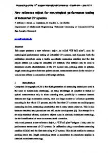
support which has to be selected for the individual functions. An analogy can be made with the mechanisation and automation which have been introduced in the production process, where there are a number of analysis models available for describing the processes which are carried out (for example, MTM studies), together with methods or general rules for how to choose the degree of mechanisation. Thus a central question is how the possibilities offered by information technology should be incorporated when building up the routines used in technical planning and control. At present, there is no set of concepts or methods available to help companies to decide the extent to which the individual functions are to be integrated, or the degree of computer support or computer-based automation. In this project I have chosen to focus on the specification activities which take place in the company. In Figure 1 below, the individual functions within the company are shown divided up into two different streams, where the horizontal stream shows activities related to the control of how an order passes through the system (the logistic flow), while the vertical stream (the specification flow) shows activities related to how the product is created specification and manufacturing.
Product Productspecification
Methodspecification
Order
Receipt of order
Planning Purchasing
Initiation
Production
Monitoring
Qualitycontrol
Figure 1. Logistic flow and specification flow within the company [Hirsch, 52]. The logistic activities in the horizontal stream can to a considerable extent be supported by general applications (standard or framework systems) such as MAPICS, COPICS or SAP,
2
as the work routines supported by these applications are similar in many companies involved in production. The activities in the vertical stream, involving specification of the product and its production, are associated with the individual company's products and production apparatus, and can thus only be supported by general applications, such as CAD or programming equipment for CNC machines, to a modest extent. For example, CAD systems primarily support the task of documentation, but not the content of the actual engineering tasks. 1 To support the tasks of specifying products and production methods, it is necessary to build up an application based on an analysis of the individual company's products and production apparatus. An essential tool in this connection is the use of product and product-related models (product modeling), which will be described in more detail in the next chapter. This project has, as previously mentioned, focused exclusively on activities in the vertical stream, i.e. specification of the product and its manufacturing process. This is the area in which production companies use a continually increasing portion of their resources, while at the same time a considerable international research effort is going into the creation of theories and methods for supporting these activities. In the literature, examples can be found of product and product-related models (see Section 2.3.3), and of theories of which knowledge and information such models should include, whereas I have not been able to find any theory for how to deduce which design and methods engineering activities in a given company should be supported by product and product-related models.
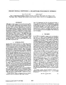
1.2 THE PROCEDURE FOLLOWED IN THE PROJECT The procedure followed during the project can be described partly in terms of an interaction between theory and practice, and partly as a combination of analysis and synthesis. In general terms, the scientific method can be described as critical rationalism, where an attempt is made to develop existing perceptions, in form of models and methods, further by making use of literature studies, investigations of logical structure, empirical work and so on. Figure 2 below shows the elements of the scientific procedures followed. Two different procedures are illustrated. In the first of these, the starting point is a problem, and an analysis phase is used in an attempt to obtain understanding of and insight into the problem domain
1
In this thesis, the terms "knowledge- and information-oriented tasks" are used as general terms for the activities which are related to the storage and retrieval of information (information-oriented tasks) and to the generation of new information (knowledge-oriented tasks). Specification-oriented tasks are in this context knowledge- and information-oriented tasks in the company's specification flow, and by engineering tasks I primarily mean the knowledge part of the knowledge- and information-oriented tasks in the company's specification flow.
3
by exposing structures and relationships etc. In a subsequent synthesis phase, models and methods for solving the problem are formulated, and the consequences of the proposed solution are evaluated.
Scientific work paradigms
Problem base
R E S E A R C H
Theory base
SYNTHESIS
ANALYSIS
Building up structures Internal consistens, etc .
Revealing structures, causality, empirical , results etc.
Diagnosis
Model
ANALYSIS
SYNTHESIS
External consistency, usability, etc.
Generation of solutions, Evaluation of consequenses
D E V E L O P M E N T
New scientific perception
New scientific perception
KNOWLEDGE TRANSFER Adaptation of methods, implementation, etc.
Practical results
Figure 2. A scientific working procedure [Jørgensen, 74].
4
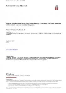
In the other procedure, the starting point is the existing theory, and a synthesis phase is used to set up models and methods which explain a given phenomenon (problem), after which these models and methods are tested in an analysis phase, in which the proposed theory's consistency and usability is evaluated. In the current project, a combination of these two procedures has been used, where I sometimes start from a problem (to set up models and methods for supporting the tasks of design and methods engineering), and sometimes start from relevant theories in this area (for task preparation, modeling of knowledge and information, product modeling and the task concept). In the figure, the scientific task is also divided into research and development, where the latter includes adaptation and implementation of research results, so that they can be used operationally in a particular company. In this Ph.D. project, emphasis has been placed on making the proposed models and methods "finished", so that they can be used in an operational manner within individual companies. Another important aspect of the project has been the use of Linstone's theory of the significance of perspectives for the solution chosen [Linstone, 87]. Linstone states that the perspectives which are adopted during analysis of a problem determine the validity of the final solution. The optimum solution to a problem seen from one point of view can be unsuitable seen from other points of view. Linstone formulates three main groups of perspectives in connection with analysis of systems: a technological perspective, an organisational perspective and a perspective oriented toward individuals. This project consider the group of technological perspectives, and when formulating an hypothesis, a number of these perspectives are used as the basis for the hypothesis, while other perspectives are more or less excluded, in order to limit the extent of the project. Efforts have been made to ensure that it is made quite clear which perspectives are included and which are excluded. Figure 3 below shows how the project has proceeded. The procedure is based, as mentioned above, on a combination of the procedures shown in Figure 2, starting partly from a problem and partly from a study of the literature in the area concerned. The empirical work has been used to contribute both to the analysis and evaluation of the chosen hypothesis, and to a synthesis in which the hypothesis was reformulated and extended.
5
Formulation of problem
Study of literature
Limitation of project and formulation of initial hypothesis
Correction and extension of hypothesis
Empirical work
Study of literature
Final hypothesis
Writing report
Figure 3. The working procedure followed in the project. The study of the literature has continued throughout the project up to the formulation of the final hypothesis. The main effort in the study of the literature has partly been expended during the early phases of the project, where the limits to the project were set and the initial hypothesis was formulated, and partly during the empirical work, during which the hypothesis was continually reformulated and extended, during the three first activities, there was some overlap and iteration between formulating the problem, studying the literature and formulating the initial hypothesis.
6
1.3 THE STRUCTURE OF THE REPORT This report is divided into four main parts (see Figure 4), where the first part deals with the theoretical basis for the project, its final delimitation, and the assumptions on which the project is based. The second part contains a formulation of the proposed hypothesis, while the third part contains a description of the empirical work which has been carried out at Alfa Laval Separation A/S. The final part contains an evaluation of the proposed hypothesis and sets the results of the project into perspective. Teoretical basis Work preperation IT-modelling Product modelling Task concept
Hypothesis Procedure The product and method specifikation task
Emprical results Specification of task and construction of model at Alfa Laval Separation A/S
Conclusion Evaluation of the proposed hypothetis and setting the project results into perspective
Figure 4. The structure of the report. The theoretical basis of the project is made up of four different elements. The first element (work preparation) contains a description of methods for determining the optimum work preparation (or support) for the technical planning and control functions within a company, and an work analogy is made with methods for analysing and preparing for the actual production tasks.
7
The second element consists of a short presentation of basic concepts and techniques for the modeling of knowledge and information, with special emphasis on the use of object-oriented modeling. In addition, there is a short description of the CIM/OSA reference model and the STEP-standard as these are expected to contribute to coming standards in this area. The third element deals with product modeling, which is set in relation to concurrent engineering and the feature concept. Reference is made to four different examples of product and product-related models, which can be considered as reference systems which determine the general content and the general structure of product and product-related models. Finally, in the fourth element, the task concept is presented and its application in Danish industry in three large Danish projects, Development of Production Systems (UPS), Company-specific Production Control (ViPS) and Focus on Development Ability (UNIC), is discussed. The theoretical discussion finishes with a definition and delimitation of the project and the assumptions on which it is based. The theoretical basis of the project forms the foundation for the hypothesis which has been formed, which involves an overall procedure for development of systems, which can support activities in the company's specification flow. The first part of the procedure involves an analysis of the system's task, expressed in terms of the product and method specification task, which - seen from a task preparation perspective - contributes to the definition of the future structure of the company's specification flow (here primarily design and methods engineering). Following this, the procedure consists of a number of phases, based on the use of objectoriented modeling, which lead to the construction of the IT systems which are to support activities within the specific company. Analysis of the product and method specification task forms the foundation for the task of building up the IT systems, as the analysis of which activities are to be supported determines the content and structure of the IT systems, which are to be built up based on the content and structure of the general reference models for product and product-related models. The project's empirical work has been carried out at Alfa Laval Separation A/S in Søborg. The empirical work has made it possible to perform an analysis of which design and methods engineering activities it would be interesting to support by IT (the product and method specification task), and to build up an application which contains knowledge and information for the support of design and methods engineering for one of the components which make up part of the company's product program (decanters). Emphasis has been placed on carrying out the whole process (formulated in the procedure), from the determination of the content and structure of the system (by use of the product and method specification task) through to the programming of an application. Finally, the proposed hypothesis is evaluated in relation to the empirical work carried out, and the hypothesis' validity is judged from the point of view of the perspectives which are used in the project. In addition, the results of the project are put into in perspective, and the hypothesis is related to other points of view, such as those of organisation and integration.
8
2. THEORETICAL FOUNDATIONS 2.1 WORK STUDY In this section I will present the general philosophy and the point of view used in this project with respect to the development of systems for technical planning and control. A technical planning and control system, as defined in [Vestager, 125] is shown in Figure 5 below. Technical planning and control involves the planning and control of the product, method and quality, together with logistics and production planning and control. Produc t Design
Handling
Proc ess
Quality
Methods
Plant
Materials
Capacity
Innovation
Specific ation
Introduction
Indirect monitoring
Direct monitoring
Produc t planning and c ontrol
Method planning and control
Quality planning and control
Logistics Production planning and control
PRODUCTION
Figure 5. Technical planning and control in the company. Product planning and control involves all activities concerned with planning, development and specification of the company's products. Method planning and control involves development of the company's production apparatus, together with specification of the running activities associated with production (routing, operational advice, cnc coding, tool design etc.). Quality planning and control is here shown as an independent activity, but can in fact be considered as a parameter which affects all activities within the company. Logistics is here used in the sense of control of the purchase of materials and subcontractor services, together with plant planning, while production planning and control involves the planning of the individual production activities, i.e. the planning of materials and operations in relation to the available capacity.
9
The technical planning and control system has arisen as a result of the extensive division of labour and mechanisation which has been introduced in production. An essential prerequisite for the improvements in productivity, which have as time goes by been achieved in production since the initial introduction of the division of labour at the end of the previous century, is the development of methods for analysing and preparing the task of production, together with the exploitation of mechanical technology to support the individual work operations. The various functions in a company which correspond to the various phases in the product life cycle are shown in Figure 6 below. The figure only includes those phases which are related to activities in a manufacturing company, so that for example phases such as the use and the disposal of the product are not included in this context. The individual activities associated with the specification and manufacture of the product are shown as consisting of three levels.
Strategic planning and coordination
Delivery
Production
Production planning og control
Quality control
Purchasing
Method engineering
Design
Sa les (Contra cting for ord ers)
Preperation/innovation
Product fabrication ( operation level ) Figure 6. The company's functions, showing the operational, preparation and coordinating levels. The operational level describes the actual work of sales, specification, purchasing, planning and manufacturing of products. The preparation level indicates the development of systems which can support activities on the operational level, for example development of the production system by changing the layout or the production equipment, or the building up of product and product-related models to support specification activities in design or methods engineering. In relation to the functions of technical planning and control shown in Figure 5, it should be noted that the activities involved in method planning and control are divided into those activities which prepare (develop) the production system, and those which, on an operational 10
level, specify the activities (operations) to be performed during production. The strategic level involves the coordination of the individual subsystems, and sets up the ground rules for building up the systems in accordance with the company's overall strategy. The preparation level in Figure 6 indicates the need to develop systems and to support functions in the company's technical planning and control, using IT, in the same way as production has up till now been developed and supported by the use of mechanical technology. In the ICAM project, this fact has, as previously mentioned, been formulated by saying that the focus of attention has changed from being "Manufacturing of the product" to being "Manufacture of the manufacturing system", which means that systems for performing the daily operational routines concerned with the specification and manufacturing of products have to be developed and implemented.
2.1.1 INFORMATION TECHNOLOGY IN TECHNICAL PLANNING AND CONTROL In connection with the development of functions within the system for technical planning and control, information technology (IT) is an important tool for achieving improvements in the efficiency of these functions. IT is developing rapidly. The price/performance ratio is dropping rapidly, and new technical possibilities (such as graphical communication using images and films) are appearing, which means that the potential area of application of IT is continually being expanded. It is especially developments in hardware which are going rapid-ly, but there is also a continual development in methods for efficient development of soft-ware, such as object-oriented systems and CASE tools [Kirkby and Kjærulf, 78]. Information technology is being used to an increasing extent in the technical planning and control system, a fact which is confirmed by several investigations into companies' use of IT; [Arthur Andersen, 13], [Foss Michelsen, 44], [Price Waterhouse/IKO, 101] and [Danish Industrial Employers' Association, 65]. In these investigations, the following trends in the use of IT in Danish manufacturing companies are indicated: • The use of IT is having increasing influence on manufacturing companies' productivity and competitiveness. • Company management is to an increasing extent involved in the use of IT. • Companies are investing more and more money in IT. In the period 1985-1991, annual costs for edp rose by 120% measured in fixed prices. • Responsibility for the development and maintenance of computer systems is being decentralised, and is to an increasing extent being taken over by the users. • External networks between companies (EDI techniques) are being used to an increasing extent. 11
The conclusions indicate that the use of IT is of increasing significance for the competitiveness of manufacturing companies. Company management is becoming more involved in the exploitation of IT, and more and more people consider the exploitation of IT to be a competitive factor on an equal footing with product development and rationalisation of production. More money is being invested in IT, and most companies experience pressure from suppliers and customers to use IT for external communication. At the same time it is stated that many manufacturing companies have difficulty in understanding the tasks of technical administration, and therefore rationalise these tasks by using IT. [Danish Industrial Employers' Association, 65] formulates this as follows: "A central question in this connection is how a company can take hold of the administrative tasks, so that they appear in such a transparent manner that the company can find a basis for managing the administrative functions and making them more efficient". In other words, there is an increased interest in using IT in manufacturing companies, and at the same time a realisation that there is a lack of methods and procedures for analysing and modeling those knowledge and information tasks within the company, which have to be supported and made more efficient by IT. In 1992, [Christensen & Clausen, 25] performed an investigation of manufacturing companies' use of IT in technical functions. The investigation, which covered 100 companies in the mechanical and electronic engineering industries, came to the conclusion that most companies use computers for design and methods engineering. The systems used are general ones, such as CAD, spreadsheets and database systems, while more advanced applications with a marked knowledge content, for example for processes selection, are only used to a small extent. In connection with the use of general knowledge-based systems for supporting design and methods engineering tasks, [Alting & Zhang, 2] have performed an investigation into the use of process selection systems (Computer Aided Process Planning, CAPP, systems). In this investigation, which considered 150 CAPP systems, it was stated: "In spite of the fact that tremendous efforts have been made in developing CAPP systems, the benefits of CAPP in the real industrial environment are still to be seen". Many resources had been invested in the development of general process selection systems, but they had not (in 1989) achieved any notable degree of acceptance in industry. The investigation concluded that one reason for the failure to apply them could be failure to achieve an overall view of the systems on offer, together with a lack of knowledge of which criteria should be used for selection and evaluation of a CAPP system. Another aspect could be that the choice of processes is related to the individual company's product and production system, so that it can be difficult to model all relevant points of view
12
for process selection in a general system which can be used in several companies, without this system being on a general level and only able to cover a small part of the company's product range. To sum up, it must be stressed, as mentioned in Section 1.1, that the activities associated with the technical planning and control system consume a larger and larger portion of the company's manpower resources. Of these activities, it is primarily the activities in the company's logistic flow (Figure 1) which have until now been supported by generic applications (such as MRP systems) which can contribute to the performance of some of the working routines in this area, while the activities in the company's specification flow, which include the design and methods engineering functions, have only to a small extent been supported by tools such as CAD and programming equipment, which does not directly help to perform working routines (the real engineering tasks), but merely support tasks such as drawing and programming. There is considerable potential in supporting the engineering activities in the company's specification flow with IT, as companies use an increasing portion of their manpower resources for these activities, and because this type of activity has until now only been supported to a modest extent. Support of such activities is, as previously mentioned, associated with the use of product and product-related models which contain engineering knowledge and information about the product and, for example, its manufacturing process. Product and product-related models contain knowledge and information about the individual company's specific products and production system, and must thus be put together individually for each particular company, possibly by the use of general (purchased) software components (Section 2.2.5-2.2.7). In this connection it is necessary to determine which activities have to be supported, and thus which knowledge and information the model must include.
2.1.2 AN ANALOGY TO TRADITIONAL ANALYSIS AND THE RATIONALISATION OF PRODUCTION WORK. In this section I shall consider some of the techniques which are used for analysing and describing the work which are performed during production, and will try to draw an analogy between traditional work analysis in production and analysis of the knowledge and information work which are performed in the technical planning and control system. In Figure 7 below, all work is considered as being made up of three elements, an intellectual element, a sensory element, and a motor element [Vestager, 123, p.14]. The motor element includes the directly physical work elements, such as grasping or lifting. The sensory element includes tasks such as the registration and identification of items, while the intellectual ele-ment involves the processing of data (sensory impressions) and the preparation of the opera-tion (knowledge and information work).
13
Intellectual work
Sensory work
Motor work
Figure 7. The elements of work [Vesterager, 123, p.14]. In connection with the mechanisation of production work, it is primarily the physical work elements (the heavy mechanical work) which is supported by mechanical technology. This is typically the case for mechanisation carried out in companies involved in one-of-a-kind and batch production, where machines perform the heavy mechanical tasks, while the sensory and intellectual work are still performed by the operator. The use of CNC machines and sensors is in this context an example of how IT is used to support the sensory and intellectual production work. Another example is in mass production, where all work elements are performed automatically, with the sensory and intellectual work elements to a great extent mechanically embedded in the construction of the production system (stiff automation). In mass production, a considerable amount of preparation for the work to be done is performed, as the elements of this work are analysed and to a considerable extent automated or mechanised. Mass production involves preparation (and automation) to a greater extent than for example batch production. Work preparation is here defined in a general manner as the preparatory work which are performed before the actual operational work. Thus the preparatory work include analysis of which auxiliary means (machines and tools) it can pay to purchase or develop for carrying out the operational work. The degree of support (here the degree of mechanisation) is in what follows generally denoted the degree of preparation. In connection with the mechanisation of production, the optimal degree of preparation is determined from an analysis of the nature of the work and the frequency with which it is carried out. By analysis of the nature of the task, we mean analysis and description of the elements of the task and determination of the relationship between the task (work element) and the machines/tools which can support this work. When the mechanical operations in production are rationalised, methods are available for analysing and specifying the work, as the individual operations are broken down into welldefined sub-operations falling in the following four categories: perform process inspect
14
transport store The individual sub-operations can then be further subdivided, for example following the principles of MTM (Methods Time Measurement) analysis, which is used to classify manual work operations, where the individual sub-operations are broken down into so-called basic elements, such as stretch, move, twist, press, grasp, adapt, release and loosen. The operations which are analysed can either be purely manual or be performed together with a machine. In the latter case, a so-called man-machine analysis is performed, describing the sub-operations carried out respectively by the employee and the machine and their relative order. The aim of analysing work operations in this way is partly to determine the time needed for the operation, and partly to minimise this time by optimising the sub-operations which are performed. Optimisation of sub-operations can be achieved in several ways. Small changes can be made to the product, so that for example it becomes easier to assemble. The task can be organised in a different way by changing the order or content of the individual suboperations. Or finally the operation can be improved by changing the equipment (machine, tool or fixture) which is used. In this last case, it is the detailed analysis of the operation which forms the basis for mechanisation of basic elements which were previously performed manually. In connection with a production sequence, there is often a combination of manual, mechanical and automatic operations. Figure 8 below shows how various operations in a sequence can be performed with various degrees of mechanisation. An example of this is in assembly lines, where in many companies there is a mixture of manual, mehanical and automatic work. Degree of mechanisation Automatic
Mechanical
Manual
Activities
Figure 8. The working procedure with varying degrees of mechanisation. "Manual operations" refers to a procedure in which the operator, possibly with limited mechanical aids, himself controls and performs the process. "Mechanical operations" refers to a 15
procedure in which the motor/mechanical work are primarily performed by a machine, while the operator still controls the sequence of operations (possibly in an interaction with the machine), while an "automatic operation" is performed without the operator directly being involved, as the operator is here typically only responsible for monitoring and control of the process. In the context of the analysis of work in a company's technical planning and control, one can in a similar way talk of a varying degree of IT support. An operation (a work procedure) can be performed without using IT (corresponding to a manual operation). The operation can be performed in an interaction with IT, where IT supports the function (corresponding to a mechanised operation), or it can be performed automatically solely by the use of IT (corresponding to an automated operation). The relationship between the task and the tool or machine is known as correspondence, where a high degree of correspondence means that the tool or machine can support the task to be performed to a considerable extent. In connection with correspondence between task and tool, the term tool homogenisation is used to denote the development of tools, such as universal grasping tools, finishing centers and so on, which can support many different tasks. Correspondingly, the term task homogenisation means that the tasks which are to be performed on a given machine or tool have been made uniform seen from a tool point of view, where we here consider a tool as a general aid, which could be a machine, a tool, a fixture and so on. Task homogenisation from a tool point of view is often used in connection with the classification of items (for example using group technology) to be processed, so that these items are uniform from the point of view of machining, handling, assembly or whatever. The various "Design for X" methods correspondingly have as their aim the design of products which are uniform with respect to machining, handling, assembly and so on. Conversely, a "manufacturing for design" review could have tool homogenisation as its aim. In the system for technical planning and control, it is, as previously mentioned, primarily knowledge and information tasks which are performed. By supporting technical planning and control activities with IT, for example by building up systems for specification of the product and its manufacturing procedure, one can in a corresponding manner talk of making the products specification-uniform (design-uniform, methods engineering-uniform, etc.) [Vesterager, 123]. The criterion for when it is optimal to support one or more sub-operations by using machines is that it must be possible to describe the operation unambiguously (it must be analysable), the operation must be performed in the same way every time, which implies that the items which are to be processed in the operation must be uniform from a tool point of view. And finally, in order that any investment in machines or equipment should be profitable, it is necessary that the operation be performed sufficiently often.
16
Tota l p rod uc tion c osts
Tota l avera ge c osts pe r prod uc t
Numb er of p ro duc ts of typ e x
Numb er of prod uc ts of typ e x
Figure 9. Cost per item for various degrees of mechanisation. The above criteria are derived from a general economical criterion, which is to achieve the lowest possible cost per item (total average costs). Figure 9 shows costs per item for varying degrees of mechanisation, where the total production costs are divided up into fixed and variable costs. By manufacturing products in large volumes, a high degree of methods engineering and mechanisation can be introduced, which minimises the variable costs per unit and thus the total average costs per item. The interesting thing about making products X-uniform by a combination of task and tool homogenisation is that in this way one achieves a higher volume of uniform operations, so that one moves further down the total costs per item curve. This fact is generally known in connection with the design of production systems, but corresponding considerations will also be relevant to the design of systems for supporting the company's specification tasks. An important tool for grouping product components according to particular manufacturing methods is the use of group technology [Burbidge, 19], [Sant, 110]. To group items, classification systems are used which group components according to various criteria, for example the grouping of axles on the basis of criteria for performing turning operations, such as geometry, materials and surfaces. There are a large number of group technology classification systems and various methods for grouping items.
17
S S2 S1 S3
D1 D2 D3
Df
Dh
H - number
v
Fb Fd Cl.nr.
DI
D2
D3
Df
Dh
S
SI
S2
S3
Fd
Fb
H
Number
V°
1
01102-3900
80
67,7
27
-
56
12
2
-
-
-
-
8,4
2
-
40
2
01102-3900
80
67,7
21
-
56
10
2
-
-
-
-
8,4
2
30
3
01102-3910
80
67,7
30
64
56
17
-
4
-
-
8,4
2
20
80
4
01102-3910
100
87
27
82
78
24
-
5
-
-
8,4
4
30
25
5
01102-3910
80
67,7
24
56
56
17
-
4
-
-
8,4
2
15
45
6
01132-3910
100
87,9
27
-
78
18
3
-
-
5
16
8,4
4
-
100
7
01132-3910
80
67,7
27
-
56
16
2
-
-
5
15
8,4
2
-
70
8
01132-3900
80
67,7
21
-
56
15
2
-
-
5
15
8,4
2
-
90
9
01102-3900
100
87,9
27
-
78
13
3
-
-
-
-
8,4
4
-
70
10
00100-2900
67,7
-
21
-
-
12
-
-
-
-
-
-
-
-
80
11
00100-2900
67,7
-
27
-
-
12
-
-
-
-
-
-
-
-
75
12
00102-3900
80
67,7
27
-
56
10
2
-
-
-
-
8,4
2
-
50
13
01132-3900
80
67,7
27
-
56
15
2
-
-
5
15
8,4
2
-
85
14
01102-3900
80
67,7
30
64
56
17
-
4
-
-
8,4
2
20
60
15
01132-3900
100
88
30
82
78
24
-
5
-
-
8,4
4
30
75
16
04102-3900
100
88
27
-
78
16
3
5
3
-
-
8,4
4
-
90
17
01100-3900
87,5
75
27
-
-
10
2
-
-
-
-
-
-
-
Run
Drawing
length
nr.
20
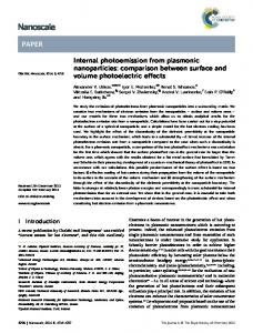
Figure 10. A complex component with 17 instances [Sant, 110, p.206]. Figure 10 above shows an example of a so-called complex component, which describes a group of components with uniform manufacturing properties. Originally, group technology was associated with the grouping of product components according to manufacturing method, so the word "technology" in group technology must be understood in the sense of manufacturing technology. [Sant, 110] draws an analogy between
18
manufacturing processes and decision processes, where group technology for a decision maker means that he has to relate uniform tasks and work out a solution for the group of tasks, rather than specific solutions for each individual task. [Sant, 110, p.37] continues: "The original idea of group technology about simultaneous processing of uniform products is extended in two areas: Products have been replaced by the more general concept of tasks, and the condition of simultaneity in the groupwise processing has been eliminated." In other words, the idea is presented that group technology should be used for knowledge and information tasks (decision processes). Continuing from there, the conclusion is drawn that with the existing classification systems (1976), there are limited possibilities for grouping uniform tasks it is only possible to group tasks in the industrial organisation which are closely associated with a product's origin. Thus group technology can be considered as a method for grouping similar tasks, so as to obtain an increased frequency, which enables us to perform methods engineering to a greater extent, and thus to move further down the cost per item curve of Figure 9. The philosophy of group technology also been seen the use of product modeling, where knowledge and information about similar products are collected in a model which forms the basis for programming an application which can support specification tasks. Thus in this Ph.D. project it has been a question of grouping similar specification tasks and supporting them by the use of product modeling. The pre-condition for using product modeling is, according to [Dataforeningen i Sverige, 34], that it is possible to set up a description of a product (corresponding to a complex component) in principle, where this description contains a description of the product's basic structure with a specification of which parts can be varied and which possible variations can be permitted within the system.
2.1.3 SUMMARY In this section, the technical planning and control functions within a company have been described. The need for analysing, developing and supporting the individual functions with IT, in the same way that the actual work of production has been analysed and supported with mechanical technology, has been pointed out, Until now, companies' use of IT has focused on supporting activities which are generic (or uniform) for a series of companies, such as a part of the activities in the companies' logistic flow, while the activities in the com-panies' specification flow, which are more specific to the individual company in relation to the company's products and production system, have only been supported to a small extent, using general applications such as CAD and programming equipment. This project focus on activities within design and production preparation. Analysis of the specification activities in these functions contributes to determining the content and structure
19
of product and product-related models (see Section 2.3.3), which support the specification work in design and methods engineering. The knowledge and information content of the activities to be supported dictates the knowledge and information which have to be modeled in the product and product-related models. We point out an analogy with traditional work analysis in production, as the criteria for determining which degree of work preparation to choose in production can form a basis for the selection of activities within design and methods engineering which are to be supported, and thus determine the degree of IT support of the individual specification activities, in the same way as production has previously been analysed and supported by mechanical technology. In connection with the determination of the degree of work preparation, there is also a connection to the earlier use of group technology in production, where attempts have been made to group items which are to get uniform treatment, in order to increase the number of items (or the frequency) and thus the optimum degree of work preparation, resulting in lower costs per item. Group technology concepts have here been extended to include grouping of similar tasks (or knowledge and information-related work) in the company's specification flow. Group technology is also associated with the use of product modeling, as one of the pre-conditions for the use of product modeling is that it is possible to produce a description in principle of the company's products, which comprise a number of variants within a given product family. In connection with the analysis and modeling of knowledge and information, a number of analysis and modeling techniques are available today which are analogues of the techniques used to analyse and model the actual work of production. In the following sections, I shall introduce a number of these methods which are used to analyse and model knowledge and information, including the various perspectives (or description orientations) which make up the overall sequence of activities (project life cycle) in the construction of IT systems.
20
2.2 MODELING OF KNOWLEDGE AND INFORMATION In this section I shall start by introducing some of the basic concepts used in modeling knowledge and information, including the three-schema architecture and its relation to the CIM project life cycle. The three-schema architecture is taken as an example of how various mappings of the system, each supporting different phases in the development of IT systems (the project life cycle), are worked out during construction of IT systems. A short introduction to IDEF modeling (functional modeling, IDEF0, and information modeling, IDEF1) will be given, together with a description of object oriented modeling, as these are general methods for analysing and modeling knowledge and information. IDEF0 modeling is described because this modeling method is an element in the project's hypothesis, to be presented in Chapter 3, which deals with the complete procedure for constructing IT systems for supporting the activities in the company's specification flow. IDEF1 modeling is primarily presented because a number of the basic concepts in IDEF1 information modeling are identical to the concepts which are used in object oriented modeling. Object oriented modeling is described in more detail, as this modeling technique is used in most of the phases of the complete procedure presented in Chapter 3. In addition to the modeling techniques mentioned above, the corresponding models for the project life cycle (ICAM's project life cycle for IDEF modeling, and the object oriented project life cycle, respectively) are presented, since, as mentioned in Section 1.3, they form the background for the way in which things proceed in the complete procedure. Particular emphasis has been placed on formulating the object oriented project cycle, as this is used directly in a series of phases in the procedure used in the hypothesis. Finally, the CIM/OSA reference model and the STEP standard are described, as theses contribute to the design of standards and frameworks in this area. CIM/OSA and STEP are not used directly in this project, but are described because it will be relevant in the long term to follow these standards (especially STEP), partly because it will become possible in the future to buy standard modules, which can be incorporated in the complete IT system, and partly because it eases the external communication between companies. The concepts, techniques and reference models mentioned here form a foundation for analysis and modeling of knowledge and information in a given domain. In this project they form the basis (the information technological tools) for being able to build up applications (based on product and product-related models, which will be dealt with in more detail in Section 2.3.3), which can support knowledge and information work in connection with the specification of the product and its manufacturing procedure.
21
2.2.1 DATA AND KNOWLEDGE REPRESENTATION FORMS In the modeling of knowledge and information systems, data, information and knowledge all have to be represented. In this section I shall start by explaining these three concepts, and then give a short description of the principles used in various forms of knowledge representation. To define data, information and knowledge refer to the process of human cognition. In this connection, data do not have any meaning before they are put into a particular context (frame of reference). When human beings receive data from their environment for example a number, a statement (he went'), the whistling of a train, etc. these data have no meaning before they are placed in a particular context. This can be explained by an example. [Kerr, 76, p.65] mentions an example with a train whistle (data), where different people who hear the whistle give the sound (the data) quite different information values. For the lonely wife, it means that her husband is on his way home, for the saboteur that his mission has perhaps failed, and for the fellow who has his foot stuck in the rails the whistle means that an accident will soon take place. Data in a particular context (frames of reference) is called information. Knowledge is associated with human ability to reason out new information from given information. In other words, knowledge can be considered as a system of data, abstractions, theories and models, which together can receive and interpret data, and thus generate new pieces of information. A system which, by using rules and procedures, starting from an existing information base (simple facts), is able to generate new information is called a knowledge base. A knowledge base contains both declarative and procedural knowledge. Declarative knowledge (what knowledge) consists of information and relationships between information, while procedural knowledge consists of procedures which can generate new information.
22
DATABASE
KNOWLEDGE BASE Simple facts (explicit)
Simple facts (explicit)
General rules (explicit) Relationships between facts (explicit)
Constraints on allowable facts (implicit)
Procedures for 'application' of rules to deduce new facts (explicit)
Figure 11. Differences between a database and a knowledge base [Kerr, 76, p.112]. Figure 11 shows the contents of a database and a knowledge base respectively. The database contains information and indirect (implicit) limits to the possible combinations of information. The knowledge base contains not only information and general rules and relationships between information (declarative knowledge), but also procedures for using rules and existing information to generate new information (procedural knowledge). There are a number of different methods for representing knowledge, for example logicbased, rule-based and object oriented methods, all of which are based on the "pattern of direct inference", i.e. a method in which new information is generated starting from existing information and well-defined rules, in contrast to neural networks, for example, which take as their starting point a set of pieces of information, and try to use these to deduce rules for generating new information (deduction machines versus induction machines). Rule-based systems consist of a database, a rule base and an inference machine, where the inference machine contains procedures which activate rules in the rule base in a given order, and thus generate new pieces of information. The rules consist of IF-THEN statements, which can be modeled in a decision tree. Searching for and activation of rules takes place either forwards or backwards in the tree structure, following procedures determined by the inference machine. Figure 12 shows the elements of a rule-based system.
23
INFERENCE ENGINE
Controls firing of rules
RULE BASE
Rule 'actions' modify database
Data matched to rule conditions
DATABASE
Figure 12. Elements in a rule-based system [Kerr, 76, p.127]. Logic-based systems rely on simple propositions which can be composed with the connectives: AND OR NOT IMPLIES
logical symbol /\ (disjunction) logical symbol \/ (conjunction) logical symbol ~ (negation) logical symbol -> (implication)
The individual propositions can be given the values true or false, after which the value of composite propositions is evaluated by using the basic algebra for combination of the truth values of the propositions. By combining propositions with known truth values, new knowledge can be derived by evaluating the truth values of the composite propositions. For programming in logic-based systems, programming languages such as PROLOG are used. Object oriented analysis is based on the use of semantic networks, i.e. networks in which the individual objects and their mutual relationships are described. A node in a semantic network can be either an object or a class of objects. In many ways, a semantic network resembles the network which is produced by drawing entity-relationship diagrams, but differs in that the individual nodes in the network (the objects) can be given a behaviour, in addition to containing information. Semantic networks also contain structures (frames), i.e. a classification of objects into hierarchies, which can either be generalisation-specialisation hierarchies or hierarchies of objects which form a whole (whole-part structure). Similarly, a semantic network can contribute to structuring the rules used in rule-based modeling, as the individual rules are modeled within the frames of the individual object. Thus in object oriented analysis, elements from both rule-based and logic-based models may be included. Object oriented analysis can be supported by object
24
oriented programming languages such as SMALLTALK or C++. The object oriented representation form is described in more detail in Section 2.2.4.
2.2.2 THREE-SCHEMA ARCHITECTURE AND THE PROJECT LIFE CYCLE 2.2.2.1 THREE-SCHEMA ARCHITECTURE Various points of view can be used in connection with the modeling of knowledge and information. Zachmann draws a parallel to house-building, where a series of descriptions of the house are produced for example a sketch of the layout of the house, for use by the purchaser, a detailed drawing of the electrical installations, for use by the electrician, and so on and points out that in a similar manner different pictures of the system are worked out during the construction of information systems [Zachmann, 132]. Zachmann introduces three different types of description for use in the construction of information systems. These respectively describe the system's data (entities), the system's processes (functions) and the physical network. Zachmann combines these three dimensions with a number of points of view, known as perspectives, which are relevant for the individual types of description in the architecture (see Figure 13). Data description
Process description
Network description
Scope description (ballpark view)
List of entities important to the business
List of processes the business perform
List of locations in which the business operates
Model of the business (owner's view)
E.g. entity/ relationship diagram
E.g. functional flow diagram
E.g. logistic network
Model of the information system (designers view)
E.g. data model
E.g. data flow diagram
E.g. distributed systems architecture
Technology model (builders view)
E.g. data design
E.g. structure chart
E.g. system architecture
Detailed description
E.g. data base description
E.g. program
E.g network architecture
Actual system
Data
Function
Communications
Figure 13. Description types and perspectives for building up information systems [Zachmann, 132, p.285]. Within each individual type of description, the individual perspectives form a sequence, in which one proceeds from a general level (and a comparatively coarse system description) to
25
a more detailed (implementation-oriented) system description. The content of the matrix makes up a complete framework for constructing information systems. In connection with the construction of information systems (databases), the so-called threescheme architecture shown in Figure 14, which in many ways is reminiscent of Zachmann's framework for the construction of information systems, is used. The first element, the external schema, involves a description of the domain and an identification of the objects (entities) which are to be included in the model. It will typically be possible to support this schema with an IDEF0 functional model together with the first phases of an IDEF1 information model. External sc hema
Conceptual schema
18
Internal sc hema
18
Equipment Type
Engineering specifications is USED as
is USED as
Conformsto 18
Determines
Equipment Specifications
18
is USED as
Equipment Callout Satisfies
Requires
18
DATABASE
Equipment Spec.Callout
Figure 14. The three-schema architecture [Vesterager et al., 127]. The conceptual schema represents the formal and logical design of the database, with a detailed specification of all entities, attributes, relations and so on. The final element describes the physical storage of the model (the internal schema), in other words the way in which the database is programmed with specifications of files, variable declarations, pointers and so on. In connection with the ICAM project [Vesterager, 124], a project life cycle has been built up in relation to this 3-schema architecture, describing the activities associated with the development and maintenance of information systems (in the ICAM project primarily related to the use of relational databases). The IDEF modeling techniques primarily support the analysis phase. The design phase is supported by traditional dataflow diagrams, and, especially in the first stages, also by IDEF1 information analysis. The use of, for example, the 3-schema architecture supports the task of modeling knowledge and information within a given domain (a particular phenomenon) and of transforming this phenomenon model into an actual system description which can be used as the foundation for building up an application.
26
2.2.2.2 THE ICAM PROJECT LIFE CYCLE In the ICAM project [Vesterager, 124], as previously mentioned, the procedure of building up information systems has been formulated in terms of the so-called project lifecycle. The project life cycle, as shown in Figure 15, contains 4 main phases: analysis, design, programming/implementation and modification/maintenance. The analysis phase contains a need analysis, in which the domain is modeled in its current (AS IS) state, and a requirements specification, in which a model which shows the system's future (TO BE) structure and method of operation is built up. Problem analysis
Maintenance and follow-up
Requirements specification
Introduction and user acceptance
Rough design
Integration & validation
Detailed design
Design & verification
Figure 15. The ICAM project life cycle [Vesterager et al., 127]. The ICAM project life cycle and the corresponding modeling techniques (IDEF0 and IDEF1) were transformed to suit conditions in Denmark in the so-called CIM/GEMS project [Vesterager, 124], which was a research and development program lasting several years, which primary aim was to transfer results from the American ICAM project for use in Danish industrial companies. In the CIM/GEMS project, the project life cycle is extended with a procedure in which the design phase is divided up into the construction of a preliminary design, involving the evaluation of various alternatives which are used in a dialogue with the user (the domain expert), and a detailed design which forms the basis for programming the system. It must also be noted that the notation used for documenting the system deviates from the IDEF notation used in the analysis phase. In the design phase, as previously mentioned, traditional dataflow diagrams are used in addition to IDEF1 modeling, while the detailed design for example uses pseudo-code.
27
The procedure is shown as a cycle for the reason that maintenance of the system involves performing a new cycle in the project life cycle, in which the same activities are carried out as were performed during construction of the first version of the system. Thus the procedure can be carried out arbitrarily many times within a given domain, as it is basically the same activities which have to be performed, regardless of whether it is a new system which is being developed, or an existing system which is being modified. The reason for introducing the project life cycle in the ICAM project was a desire to attain a more structured procedure for development of EDP systems. In the project life cycle, emphasis is laid on performing analysis and design tasks, in which the system's content and structure are specified and evaluated before actual programming work is started. In this way the overall costs of development work are reduced, as the effort expended on analysis and design, as shown in Figure 16, as a rule leads to a considerable reduction in the effort needed for programming, implementation and maintenance.
Use of ressources
Traditional procedure
Structured procedure
TIME Analyse problem
Formulate and Introduce solution
Build and introduce solution
Implement and maintain solution
Problem analysis Requirement specification
Rough design Detailed design
Building and testing Integration og validation
Implementation and user acceptan Maintenance and support
Figure 16. Savings through use of a structured procedure [Vesterager et al., 127]. The ICAM project life cycle helps to structure and divide up the task of developing EDP systems, and involves both the technical and management aspects of the development task. In other words, the project life cycle both supports the technical activities involved in developing EDP systems and works as a management tool for planning and organising large development projects, as they can be broken down into a series of sub-activities with welldefined results, such as an AS-IS model, a TO-BE model, a preliminary design and so on.
28
2.2.2.3 THE OBJECT-ORIENTED PROJECT LIFE CYCLE The object-oriented paradigm for system development attempts to integrate the individual phases of the project life cycle by identifying, at an early stage in the analysis phase, the objects in the domain which the system deals with. The identified objects are subsequently developed and described in detail in all phases of the project life cycle, which in fact contains the same phases as the ICAM project life cycle: Analysis Design Development/ implementation Modification/ maintenance Figure 17 below shows the object-oriented project life cycle, which, in comparison to the ICAM project life cycle, makes it easier to jump round between the different phases of system development. This is because here, in contrast to previously where system developers had to change representation form between the various phases, the same way of dividing things up and the same basic representation form are used in all phases of system development - it is the same objects which appear in the different phases of the project life cycle.
Analysis
Design
Evolution
Modification Figure 17. The object-oriented project life cycle [Booch, 16, p.204]. The model resembles the classical "waterfall model", where the overlapping arrows and the reversed arrows attempt to illustrate the idea that system development based on the object-
29
oriented paradigm, as stated, offers better possibilities for jumping between the individual phases of the project life cycle. In the overall procedure followed in the Ph.D. project, to be described in Section 3.2, objectoriented analysis has been chosen as the common modeling technique from the con-struction of the model to the programming and maintenance of the system. The basis for this choice has been the requirements that: • it should be possible to define a structure for a complex area of knowledge and information. • it should be possible to re-use analysis results throughout the project life cycle from analysis to design, programming and maintenance of the model. • domain experts (such as designers and production engineers) should be put in a position to model their areas of work for themselves. • a more appropriate division of work between the model builder (domain expert) and the developer of the computer system should be made possible. • In the literature, a number of properties of object-oriented analysis are presented. For example, [Coad and Yourdon, 30, pp. 35-36] present the following features (advantages) of using object-oriented analysis: • It becomes possible to analyse more complex domains. OOA helps us to understand and to structure the domain. • It improves the cooperation between the domain expert and the developer of the computer system. • It ensures the consistency of the analysis result throughout the project life cycle. The use of attributes and methods (services) in different phases of the project life cycle helps to ensure the direct application of the analysis result in design and programming. • It focuses on the common features of the objects (generality). OOA uses inheritance to exploit common features of the objects' attributes and methods. • It leads to specifications which can stand modification. OOA constructs models which are stable in relation to changes, amongst other things by focussing on the most stable elements the domain and making them the top-level object classes. • It ensures re-use of analysis results. • It ensures a consistent representation for analysis and design. OOA uses a notation which means that an analysis model (OOA) can directly be extended to give a design model (OOD).
30
An important characteristic of object-oriented analysis is thus the possibility of being able to structure a complex domain by dividing the domain up into subject areas and objects. The chosen structure is maintained throughout all phases of the object-oriented life cycle, which eases the transition between the individual phases and contributes to a more consistent use of the results which are produced in the different phases. The fact that the same way of dividing things up and the same notation are used in the different phases of the object-oriented life cycle leads to an improved collaboration between the domain expert and the developer of the computer system, and to it being possible to divide tasks between the expert and the developer, so that for example the domain expert builds the OOA model and contributes to building the OOD model in collaboration with the system developer, who then takes over the further task of programming the model [Arngrimsson, 12]. In addition the object-oriented modeling technique aims at constructing models which are stable in relation to changes, by amongst other things focusing on the most stable elements in the domain and making them object classes, while those elements which vary within the individual objects are as far as possible modeled internally within the individual objects, for example as the object's variables. Finally, attention is focused on exploiting the common features of objects via inheritance of the objects' attributes and methods.
2.2.3 IDEF MODELING In this section I shall give a short introduction to function modeling (IDEF0) and information modeling (IDEF1). IDEF0 and IDEF1 were developed in the ICAM (Integrated Computer Aided Manufacturing) project, a 10-year research program run by the American ministry of defense [Vesterager, 124]. The starting point for both IDEF0 and IDEF1 is to define the purpose, viewpoint and context for the analysis. The context delimits the model and defines the interfaces to other systems. The viewpoint defines the model builder's starting point, for example a technical, management-related or external customer point of view. The purpose defines the aim of building the model, for example to clarify the system's functional operation, or to create the basis for implementing a computer application.
2.2.3.1 FUNCTION MODELING (IDEF0) IDEF0 technique [ICAM, 62] is based on the so-called SADT technique (Structured Analysis and Design Techniques, developed by Softech), which has formerly been used as an analysis technique in system development projects. In function modeling, the functions (tasks) are mapped onto a limited part of the company (defined in the context of the model). In function modeling, the starting point is the following description of a function:
31
Control (limitation)
Input
Function
Outpu
Mechanism (aid) Figure 18. The basic elements of IDEF0 modeling [ICAM, 62, p.59]. • Function: An activity, action, process or operation. Is described by an active verb, such as "specify component" or "produce component". • Input: Physical objects or pieces of information, which are needed for performing the function. Input is transformed in the function. For example: materials are transformed by the function "produce component". • Output: Physical objects or pieces of information, which are the results of or are produced in the function. For example: "finished component". • Control: Pieces of information which determine or possibly initiate the performance of the function. For example: a production order. • Mechanism: A person, machine, computer system or the like, which performs the function. The individual functions (boxes) can be broken down into sub-functions, which describe the function in more detail, as required. For example, the function "produce component" can be broken down into a series of sub-operations, which can in turn be broken down into the subfunctions "procure materials and specifications", "set up machine", "perform operation", "check component" and "pass component on to next operation". Figure 19 below illustrates the principle in this hierarchical decomposition.
32
More general A-0
A0
A1 A3
A12
A32
More detailed
Figure 19. Hierarchical decomposition of a model [ICAM, 62, p.20]. In addition to its basic elements, IDEF0 contains a syntax and a set of rules which ensure suitable and consistent modeling. For example, all input and output which appear on a diagram also appear on the diagrams which are produced by the breakdown process. The procedure used to build up an IDEF0 model can be described in short as follows, using the phases recommended by ICAM: • Phase 0: Initial delimitation of the problem. • Phase 1: Specification of the factors which the work is based on, such as resources, project organisation etc. • Phase 2: Clarification of the purpose, viewpoint and context. • Phase 3: Collection of data. • Phase 4: Production of a preliminary model. • Phase 5: Review and revision of the model. • Phase 6: Documentation of the final model.
33
The result of an IDEF0 model is a description which specifies the model's context, perspective and purpose, the graphical model (diagrams), with an overall diagram, explanatory text, glossary of terms, explanatory diagrams and references to other models, including an IDEF1 model, if any.
2.2.3.2 INFORMATION MODELING (IDEF1): The IDEF1 technique [ICAM, 63] and [Clausen, 27] is a further development of EntityRelationship modeling developed by [Chen, 23]. The technique is used to analyse and structure information within a company, and involves methods for building up a conceptual model of a company's information system. In IDEF1 modeling, no requirements are placed on the type of database, and modeling can thus take place independently of how the computer system is imagined implemented. To introduce the basic concepts of IDEF1 modeling, I shall here relate these concepts to tables in a database. Figure 20 below shows such a table, in IDEF1 notation known as an entity class, where a row in a table, according to IDEF1 notation, is represented by an entity, a column by an attribute class and a single value by an attribute.
Attribute classes
Entity classes
Columns in table. Each column is an attribute class..
Each table in the relational database is an entity class.
SUPPLIERS
Entities
Attributes
Data values in a row. Each row is an entity.
Data values in a column. Each column can have many attributes.
Figure 20. Elements in a database [Vesterager et al., 127]. An entity class is described by its attribute classes. An attribute class which can uniquely identify an entity (a row in the table) is called a key attribute class. In addition, the IDEF1 technique describes the relationships between the individual entity classes by means of the following types of relation: - one to one (specific)
34
- one to one (non-specific) - one to many (specific) - many to many (non-specific). The different relation types are referred to as the cardinalities of the relations. A "one to one" relation implies that an entity is related to at most one entity in the related entity class, while "one to many" and "many to many" relations imply that zero, one or many entities in a given entity class are related to zero, one or many relations in the related entity class. That a relation is specific means that for a given entity in a so-called dependent entity class there will always be an entity in the related entity class. An IDEF1 model is developed in five phases, where the preparatory phase, following American practice, is denoted Phase 0: Phase 0: In the preparatory phase, the foundation for the modeling task is established, and an overall view of the existing material is created. The result of Phase 0 is that the purpose, viewpoint and context for the model are specified, together with a collection of source material, grouped into a source material list, which is a raw list of the source material which forms the basis for the project, and a source data list, which contains the data to be found in the source material, sorted according to an unambiguous source data number. Phase 1: In Phase 1, the model's entity classes are defined on the basis of the source data list. The result of Phase 1 is an entity class list, with the name and number of all entity classes, together with the entity class definitions, which define each individual entity class and describe the abbreviations which are used. Phase 2: In Phase 2, the relations between the individual entity classes are specified, and entity class diagrams are drawn. To identify the relations, a relation class matrix is worked out. This matrix is a schema, in which the group of entity classes appears both in the rows and the columns, and a relation between entity classes is indicated by a cross in the relevant field. A relation class list with corresponding relation class definitions is worked out as the relations are specified. Entity class diagrams are drawn for each entity class, showing the related entities and the corresponding relations. Finally, an overall diagram, which shows all the entity classes and their mutual relationships at once, is drawn. Phase 3: In Phase 3, the entity class diagrams are developed, so that they only contain specific relations. In addition, attribute classes and key attribute classes (i.e. attribute classes which can uniquely identify entities in the entity class) are identified, and these are used to draw attribute class diagrams, in which the specific relations together with key attribute classes and local attribute classes are shown. To support the task of identifying the attribute classes,
35
an entity class - attribute class matrix, which gives the relationship between entity classes and attribute classes, is worked out. The task of transforming non-specific relations to specific ones is supported by an attribute class migration index, which shows which entity classes the individual attribute classes are inherited to, and an inherited attribute class cross reference, which for each inherited attribute class shows which entity class owns the attribute class. Phase 4: In Phase 4, the model is refined by specification of the remaining (local) attribute classes and where they belong. In addition, the individual attribute classes and their ownership is checked. Figure 21 shows the procedure used to build up an IDEF1 information model.
36
PHASE 0 Purpose Context View Users wishes an requirements
PHASE 1 Entityclasses
Phase 1 model
PHASE 2 Relationclasses
Entityclasses arise in all phases
Phase 2 model
PHASE 3 Attribute- and key classes
Phase 3 model
PHASE 4 Attribute user classes
Phase 4 model
Figure 21. Procedure for building up an IDEF1 information model [Clausen, 27, p.12].
37
2.2.4 OBJECT-ORIENTED MODELING Object-oriented modeling is, like IDEF modeling, an analysis method for modeling knowledge and information in a given system (the real world), where the system is broken down into sub-elements (component parts). Object-oriented modeling differs from IDEF modeling in that the individual objects are associated with a behaviour, i.e. functions which the individual objects can perform for example, carrying out a calculation or presenting information. In addition, object-oriented modeling is characterised by an object being able to inherit information and procedures from other objects (inheritance) and by the individual objects' information and procedures being encapsulated (encapsulation), so that the individual object is defined by a short description of its function and the arguments which are needed to call (activate) the object and bring it to execution. This makes it possible for objects to be handled and re-used with a minimum of knowledge about the object's internal structure and behaviour. The object-oriented philosophy can be illustrated by respectively considering the structure of traditionally developed software and software developed by the use of object-oriented modeling and programming. Figure 22 below shows the structure in the software in relation to a given problem domain in the object-oriented philosophy, the same structure is used in the program and the problem domain, as the program is built up of objects corresponding to the objects which can be identified in the domain. Problem domain
DATA
Problem domain
DATA
PRO CEDURES
PRO CEDURES
DATA PRO CEDURES
Software representation
Software representation
TRADITIONAL REPRESENTATION
DATA PRO CEDURES
OBJECT-ORIENTED REPRESENTATION
Figure 22. Structure in traditional and object-oriented software [Agida, 1, p.10]. An object is partly an abstraction of an element in a domain, and partly an element in a piece of software described by an identity, a state and a behaviour. A number of definitions of objects are found in the literature. Below is given two definitions of objects, both of them covering objects as program elements and objects defined in a domain: "An object has state, behaviour and identity; the structure and behaviour of similar objects are defined in their common class; the terms instance and object are interchangeable." [Booch, 16, p.77]
38
"Object. An abstraction of something in a problem domain, reflecting the capabilities of a system to keep information about it, interact with it, or both; an encapsulation of attribute values and their exclusive services. (Synonym: an instance)." [Coad & Yourdon, 30, p.53] According to [Oxford, 99, p.86], abstraction means the principle which involves ignoring those aspects of a domain which are irrelevant with respect to the purpose, so that one can concentrate on the relevant ones. Thus abstraction is associated with those perspectives and that purpose which are used in modeling a domain. In the definitions referred to, the concept of classes appears as a synonym of the concept of objects. [Booch, 16, p.93] defines classes as follows: "A class is a set of objects that share a common structure and a common behaviour." Thus a class is a collection of objects with identical characteristics. A class of objects is modeled in the same way as an individual object. The concept of an instance is also associated with objects, and according to [Arngrimsson, 9, p.78] denotes a specific object or an individual example from a class. An instance is in itself an object, and thus has an identity, a state and a behaviour. In the following description of modeling, no distinction is made between an object, a class and an instance, as these are all modeled in the same way. Object-oriented analysis consists of two elements, an analytic part, in which the domain is broken down into elements (objects) and the individual elements are analysed and described, and a synthetic part, in which the structure of the elements and their interplay with the remaining elements is specified. In this Ph.D. project, specification of the purpose, viewpoint and context for the model, derived from ICAM's IDEF modeling, is used as the basis for building up the objects' structure. Object-oriented analysis involves three different forms of description: • An information perspective, which describes the object's data, corresponding to the content of entities in IDEF1 analysis. • A functional perspective, which describes the object's behaviour, i.e. the procedures which the object can perform. • A dynamic perspective, which describes the dynamics of the individual objects and of the overall system, by specifying (simulating) the order in which the individual objects call one another. Figure 23 below shows the notation used in object-oriented analysis, as defined by [Coad & Yourdon, 30]. The notation applies both to individual objects and to classes of objects. A class of objects is a description of one or more objects which have similar properties (attributes) and procedures (services), together with a description of how new objects in the class can be created.
39
Class & object
Class
Class & object
Name ( top section )
Class
Attribute 1 Attribute 2
Attributes ( middle section )
Attribute 1 Attribute 2
Service 1 Service 2
Services ( bottom section )
Service 1 Service 2
Whole
Generalization
Whole-part connection 1,m
Gen-Spec Structure
1,m 1
Specialization 1
Specialization 2
Part 1
Class & object 1
1 Part 2
Class & object 2 1
Instance Connection 1,m
Sender
Reciever Message Connection
Figure 23. Object-oriented notation [Coad & Yourdon, 30, p.196]. The figure shows the following types of relation between objects: 1. Whole-part structures, which define objects which are different, but which form parts of a whole, for example parts of a car: wheels, seats, steering wheel etc. Relations in wholepart structures are also defined by their cardinality. Thus a seat corresponds to exactly one car, corresponding to the specification of cardinality in IDEF1 notation. 2. Generalisation-specialisation structures, which define objects with common information (attributes) and procedures (services), as for example in the case of a car object, which contains general information and procedures about cars, and objects which describe particular groups of cars, such as goods vehicles and lorries, with corresponding information and procedures describing the specific group.
40
3. Instance connections, which describe relations between individual objects (instances) in the model. As in the case of whole-part structures, this type of relation is also described by its cardinality. 4. Message connections, which describe the information (message)which is sent from a sender object to a receiver object in order to have a procedure executed. In the following sections, the individual phases in the object-oriented project life cycle (analysis, design and programming) are described in detail, with the main emphasis laid on presentation of the procedure used during object-oriented analysis.
2.2.4.1 OBJECT-ORIENTED ANALYSIS Object-oriented analysis [Coad & Yourdon, 30] builds on the use of concepts from existing methods for information and data modeling, i.e. entity relationship diagrams (such as IDEF1) and semantic data modeling. The concepts of attributes, instance connections, generalisation/specialisation and whole/part are taken from these methods. In addition, elements from object-oriented programming and knowledge based systems which provide the concepts of exclusive procedures (services), communication with messages, generalisation and specialisation, and inheritance are used. In building up an object-oriented analysis model (OOA model), the activities indicated in Figure 24 below, in which the OOA model is described as consisting of five layers, are carried out. The individual activities (layers) can be thought of as different perspectives, which together make up the OOA model. The activities are usually performed in the order in which they are listed, but can also be carried out in any arbitrary order. In practice the modeling task is performed as a series of iterations among the various layers of the model.
Subject layer Class and object layer Structure layer Attribute layer Method layer Figure 24. The five layers of OOA modeling [Coad & Yourdon, 30, p.54]. •
The subject layer contains a sub-division of the complete domain which is to be modeled in different subject areas. In relation to the use of product and product-related 41
models, a subject area can for example be a product model or a factory model (see Figure 40). •
The class and object layer contains a list of the classes and objects which have been identified in the individual subject areas.
•
The structure layer contains the relationships between the objects, i.e. a specification of generalisation-specialisation and whole-part structures.
•
The attribute layer contains a specification of the information associated with the individual objects, i.e. what the objects know about themselves.
•
The method layer contains a description of the individual objects methods (procedures), i.e. what the objects can perform.
A more detailed description of the individual layers and the procedures used can be found in [Coad & Yourdon, 30]. As a basis for building up an OOA model, it can also be useful to perform an analysis of the system's functionality by using IDEF0 functional modeling, as described in Section 2.2.3.1. In this way one obtains a more detailed understanding of the workings of the domain, and thus an improved basis for being able to identify the individual elements in the 5-layer OOA model.
2.2.4.2 IDENTIFICATION AND CHARACTERISATION OF OBJECTS (OOA) In this section I shall present the procedure used to identify subject areas and objects, and to specify the objects' characteristics and mutual relationships. I also refer the reader to Section 3.4, where the procedure and the notation used during this Ph.D. project are described in more detail by means of a simple example concerned with the manufacture of shelves. In Figure 25 below, the content of the OOA model is illustrated, using OOA notation.
42
3
3 OOA Model Name 1,m
1 Subject Number Name Symbol
1,m 0,m 3
3 2
1,m Structure
2
Name Symbol
1
1
2,m
2
InstanceConnection AmountOrRange1 AmountOrRange2 Symbol
1,m 2
Symbol
Gen-SpecStructure
Class-&-Object (or Class) 0,m
MessageConnection
0,m
2 0,m
Name Symbol ObjectStateDiagram
2
0,m
0,m
1 1 Attribute Name Description Constraints
WholePartStructure AmountOrRange1 AmountOrRange2
1 2
Service Name Parameters ServiceChart BulletList
1
1
Figure 25. An OOA model showing the content of an OOA model [Coad & Yourdon, p.205]. Firstly, the model contains a description of the individual objects or classes of objects, defined by the objects' properties (attributes) and procedures (services), and also including the relationships between the objects in the form of instance connections or message connections. Secondly, the structures of the individual subject areas have been determined in the form of whole-part or generalisation-specialisation structures. And thirdly, the domain has been divided up into subject areas (subjects). An object is defined as a element in a domain, which is able to perform in a system by containing information or is able to execute procedures. A class is a description of one or more objects, including how new objects in a class can be created. In this presentation, as mentio-
43
ned previously, I have chosen to use the word "object" to refer both to an object and a class of objects. When identifying objects in a domain, one can amongst other things search for structures in the domain and for functions (procedures) which can be performed within the domain. In addition, it is possible to focus on which information and procedures are necessary in the given system context, including which general properties and procedures are associated with the domain. During identification of structures, a distinction is made, as previously mentioned, between generalisation-specialisation structures and whole-part structures. Generalisation-specialisation structures are identified by starting from the individual objects and investigating whether it would be appropriate in the context (responsibility) of the system to generalise or specialise the object's properties or procedures. If there are many generalisation-specialisation structures in the domain, one should start by identifying the simplest and the most detailed structures, and then determine the remaining generalisation-specialisation structures. Whole-part structures are identified by grouping objects which together form a whole for example, components in a parts list (assembly-parts), objects which can be contained in other objects (container-contents), or objects which together form a collection of objects (collection-members). The individual objects are considered as respectively whole-objects and part-objects in the hierarchy, and the object's contribution to the complete system is evaluated. If the object only contains a status value, the object is removed, and the object's status is instead added as a property of the topmost object in the hierarchy. Subject areas are defined partly in order to make it possible to get an overall view of an otherwise large and complicated model, and partly to organise the resulting system (the program) into well-defined units. A subject area is defined by grouping the uppermost objects in the structures which have been found, together with the remaining objects according to subject. For example, objects which describe a product's construction can be placed in one subject area, while objects which describe the product's manufacturing process are placed in another subject area. An effort is also made to minimise dependencies (structures and instance connections) and communication (message connections) between different subject areas, so that objects which are often connected with one another are as far as possible collected in the same subject area. An object can appear in more than one subject area, in as far as this will make the model easier to understand. Properties (attributes) describe the object's current state, and are identified by asking how the individual objects are described (what must the object know about itself?), and which different states the object can be in. A property can be described by a single value or an array (table) of values. When identifying properties in a generalisation-specialisation struc-ture, the general properties are placed uppermost in the hierarchy, while the specific proper-ties are placed at the bottom of the hierarchy.
44
Properties are as far as possible denoted by terms which are used within the domain, and a permissible interval of values is given, together with units for the values (such as kr., kg., meters etc.). In addition, any limitations on the property, such as dependencies on other properties, are specified. Instance connections denote relationships between objects which are naturally related to one another, such as the object "car" and the object "car owner", and are thus in many ways similar to a whole-part structure. In instance connections, the cardinality of the relation is specified, as shown in Section 2.2.3.2. Procedures (services) denote a given behaviour which the individual object is responsible for demonstrating. Procedures are identified by starting from the various states which an object, according to its specified properties, can be in. This can if necessary be done by using an Object State Diagram, which shows the different states which an object can be in. During the determination of procedures, attention is focused partly on simple procedures, such as creating or making a connection to an object, or definition of the value for a property (attribute value) in an object, and partly on complex procedures, which in turn are divided up into two categories, involving respectively the calculation of object attribute values and the displaying of object attribute values. Procedures are found by asking which calculations the object is to perform, and which information the object is to display. If necessary, procedures can be represented by means of a socalled procedure chart notation (Service Chart Notation) shown in Figure 26 below. Condition (if; precondition; trigger; terminate)
Text block
Loop (while; do; repeat; trigger/terminate)
Connector (connected to the top of the next symbol)
Figure 26. Procedure chart notation [Coad & Yourdon, 30, p.157]. Message connections denote connections in which an object calls another object in order to have a procedure executed. Message connections are found by investigating, for a given object, which procedures in other objects have to be called, and correspondingly which other objects that call procedures are to be found in the given object.
45
2.2.4.3 OBJECT-ORIENTED DESIGN When a system is being built up, the perspective changes from being domain oriented (what and which task?) to being implementation oriented (how?). Thus in the design phase it is made clear how the specified objects cam be implemented most efficiently using given software. To put it another way, the analysis model is moved over into a specific hardware and soft-ware environment, which is used as a tool for building up the specified system. As stated previously, the design phase is made considerably easier by the use of OOA analysis, as the OOA model forms the immediate basis for the OOD model, which in rough terms is produced by giving more details of the individual objects and if necessary by adding new objects. In the design phase the 5-layer model from object-oriented analysis (Figure 24) is used. In addition, according to [Coad & Yourdon, 31, p.24-26], four perspectives are used during development of the OOD model: • User interface, which determines the user's communication with the system. • Problem domain, in which the OOA model is corrected in accordance with design-specific criteria. • Data management, where the structure of the stored data and methods for control of data are modeled. • Task management, which is used in cases where the system has to perform several tasks simultaneously (multi-tasking). Subject layer Class and subject layer Structure layer Attribute layer method layer
Data Problem Taste User control domain control interface component component component component
Figure 27. Procedure for building up an OOD model [Coad & Yourdon, 31, p.26]. Figure 27 above shows the overall procedure for building up an OOD model. In the user interface perspective, the way in which the user can check and communicate with the system, and the way in which the information in the system is to be presented to the user (screen layouts and printouts) are specified. Starting from an analysis of the way in which the users perform the tasks, a detailed design of the user dialogue is built up, together with an objectoriented model of the system's screen layouts and output procedures. The problem domain perspective takes as its starting point the OOA model, and corrects this to match design-specific criteria. This involves evaluating the structures which are specified in the OOA model in relation to the structures which can be handled by a given programming language. The OOA model is checked for errors and omissions. If for example units or value intervals have not been given for the attributes in the OOA model, then they are added 46
in the design phase. Efforts are made to minimise the number of changes in relation to the OOA model, in order to preserve as close a relationship as possible between the original OOA model (the domain model) and the final program code. The data management perspective models the structure of the stored data and determines the method for controlling these data. The starting point here is the choice of basic database principle, which according to [Coad & Yourdon, 31, p.80] can be divided into: • Storage of data in sequential files. • Storage of data in a relational database. • Storage of data in an object-oriented database. It lies in the nature of things that the choice of database principle is closely associated with the choice of programming language. For each principle there is a general procedure for building up the design (structure) of the database and a set of methods for controlling data. The task management perspective is, as stated, only relevant in those cases where the system has to be able to perform several tasks at the same time. Task control is based on an analysis of the dynamic aspects of running the system, including a specification of which tasks have event-based or temporal dependencies. The tasks are given a relative priority and a function for temporal coordination and control of the tasks is constructed. For further details of the procedure used in object-oriented design than we have given in this short introduction, we refer to [Coad & Yourdon, 31]. The advantages of using objectoriented design (OOD) are, according to [Booch, 16, p.215]: • OOD encourages a greater degree of re-use of program code and design results. • OOD build up systems which are more robust with respect to changes. • OOD reduces the risk in system development, amongst other things because the development task can be broken down into smaller and more easily dealt with units. Object-oriented design contributes, like the other phases of the object-oriented project life cycle, to a structured procedure, and thus makes it possible to control the entire project more closely.
2.2.4.4 OBJECT-ORIENTED PROGRAMMING In this section I shall discuss the factors associated with the use of object-oriented programming, and some existing object-oriented programming languages will be presented. Objectoriented programming has become more and more widespread since the beginning of the 1980s. During the same period there has been a rapid development of various object-oriented programming languages. Today there are more than 100 different object-oriented 47
programming languages. Some of the most common such languages are listed below [Booch, 16, p.473]: • Simula • Quick Pascal • Turbo Pascal • C++ • Smalltalk • CLOS (Common Lisp Object System) These programming languages can be divided into two main categories, of which one category (Simula, Quick Pascal, Turbo Pascal and C++), which are based on ALGOL, have their origins in procedural programming, where systems are built up from procedures and functions, while the other category (Smalltalk and CLOS), which are based on LISP, have their basis in the development of systems for representation of artificial intelligence, where predicate logic is used to represent the knowledge which exists in a given domain. An object-oriented model can in principle be programmed in both an object-oriented and a non-object-oriented programming language. Graham stresses the following advantages of using object-oriented programming languages [Graham, 47, p.51-52]: • It becomes possible to re-use previously produced code. • There is an improved possibility for extending existing programs. o It supports a welldefined set of concepts, which can be used both for analysis and programming. In this way it becomes possible to model complex relationships, it becomes possible to structure the tasks of both analysis, design and programming, and finally one obtains an easier and more direct transition between the individual phases of the development process. In addition, it becomes easier to maintain the system. With respect to the first two points it must, however, be noted that the development of object-oriented programming languages is proceeding very rapidly, which may mean that current programming languages will be replaced by new languages which are not necessarily compatible with existing languages, with the result that existing code and the corresponding class libraries cannot directly be re-used. A class library is an hierarchy of objects which describe patterns of inheritance and relationships between objects. Another important aspect of the use of object-oriented programming is, that if one uses an object-oriented programming language then the design model is a sufficient basis for programming, and can be used directly as documentation [Booch, 16].
48
2.2.5 THE CIM/OSA REFERENCE MODEL In the next two sections I shall illustrate the efforts which are being made internationally to build up frameworks and standards for developing IT systems in industrial companies by describing two large international projects, known respectively as CIM/OSA and STEP. This section deals with the CIM/OSA model, which is the result of an extensive ESPRIT project, whose aim was to build up a reference model for the use of IT in industrial com-panies. CIM/OSA (CIM Open Systems Architecture) is an ESPRIT project which is being carried out by a consortium consisting of 21 companies from seven European countries. The big computer companies IBM, Digital, Siemens and others take part in the consortium, together with companies which use computers, such as AEG, Fiat and Volkswagen. Procos A/S takes part from Denmark. According to [ESPRIT-AMICE, 39], the background for the project for companies which sell computer systems is the rapidly expanding number of new software products, with hard competition on price and with rapid market changes, leading to rapid obsolescence of the products. For the users, the background is the lack of attention to the new possibilities which IT offers, inaccessible and inconsistent information systems, in which information is made poor use of, and difficulties in handling the organisational aspects of introducing IT. The aim of CIM/OSA is to support the IT producers' development of new IT systems and manufacturing companies' use of IT systems by designing a CIM reference architecture [ESPRIT-AMICE, 39, p.16]: "The purpose of a CIM Reference Architecture is to define generic structures for the completely structured description of the enterprise as a SYSTEM. This description has to include the dynamic behaviour of its manufacturing processes, its information processes and its management processes. Specific emphasis has to be placed on the Information Technology support environments for system design, maintenance and operation. Only if all three are considered simultaneously will system consistency be achieved." The participants want to build up a generic model (a framework) for all companies, which will include a complete description of the company as a system. Attention is focused on supporting the functions within the company by using IT, with emphasis being laid on the integration of design, use and maintenance of IT systems. Figure 28 below shows the main CIM/OSA reference model (framework), which involves three dimensions. One of these dimensions (drawn horizontal) relates to the generality of the model, described by the levels generic, partial and particular, where the generic level describes all companies, the partial level describes a group of companies, for example with a particular line of business, and the particular level describes a specific company (an instance). Instantiation denotes a stepwise concretisation, where one proceeds from the generic to the particular level.
49
Organisation view
Stepwise generation
Information view
Funktion view
Resource view
Resource view
Resource view Information view
Information view Funktion view
Organisation view
Organisation view
Funktion view
Generic requirements definition building blocks
Partial requirements definition models
Particular requirements definition model
Generic design specification building blocks
Partial design specification models
Particular design specification model
Generic implementation description building blocks
Partial implementation description models
Particular implementation description model
Stepwise deriviation
Stepwise instantiation
Figure 28. The CIM/OSA reference model [AMICE, 39, p.21]. The second dimension (drawn vertical) involves three levels which describe different phases in IT systems' project life cycle: requirements specification, design and implementation, where the design level in the CIM/OSA model acts to separate user requirements from system implementation, and to ensure an appropriate relation between them. The third dimension (drawn perpendicular to the paper) involves four different points of view: function, information, resource and organisation. The function view reflects the company's activities and business processes in a hierarchical structure. The information view reflects the information in the company by using entity modeling based on the 3-schema architecture, corresponding to IDEF1 modeling. The CIM/OSA follows the ISO standard in this area. The resource view reflects the resources, corresponding to mechanisms in IDEF0 modeling, such as machines, computer systems and persons. The organisation view reflects the organisational structure within the company, defining responsibilities for the elements in the remaining views (function, information and resource). The CIM/OSA project group attach great importance to the organisation view, since this view exposes the company's decision processes.
50
With the help of this reference model, CIM/OSA aims to support the development of IT systems by software companies and the procurement and use of IT systems by manufacturing companies. The requirements on the reference model can be expressed as follows: • The generic and partial parts of the reference model (and the standards and architectures built up here) must support the task of building up models for specific companies. • The reference model must be able to describe the decision systems, organisation, activities, business processes and information and materials flow within the company in a manner which can directly support the implementation of IT systems. • The models which are developed and the systems which are implemented must be flexible with respect to changes resulting from changed user requirements. • The reference model must support the design, implementation and operation of IT systems in many different lines of business. • The reference model must support software manufacturers' design, implementation and marketing of IT systems (larger markets, ensuring integration of different suppliers' products, ensuring inter-organisational communication etc.) • The reference model must support the design of the company's systems and ensure consistency in the models, so they can be changed or extended by the introduction of new IT systems or by changes to existing ones. • The operational level (implementation description) in the reference model must contribute to the integration of information handling between different areas of the company. The main aim of the reference model is to support work on development and implementation of IT systems (CIM systems) through the design of company-specific models which, taking the structure in the reference model as starting, are mutually consistent. The requirements specified for the reference model are relatively general and reflect a high level of ambition. The reference model must deal with all elements in the company which are related to IT systems, and with companies in many different lines of business. Figure 29 below shows the content of the different modeling levels (requirements specification, design and implementation) on the particular level (the company-specific level). The figure also shows the procedure used to build up a model, where one passes through the phases of requirements specification (requirements definition model), design (Design specification) and implementation (implementation description model). In what follows we shall mainly go into more details of the requirements specification.
51
Enterprice
Implementation description model
Design specification
Requirements definition model
Activity
Structure
¤ Information ¤ Function Material ¤ Constraints ¤ ¤ Resource
¤ Rules ¤ Organisation
Function model
Information model
Resource model
Organisation model
Enterprise system requirements
Function model
Information model
Resource model
Organisation model
Enterprise system constraints
Function model
Information model
Resource model
Organisation model
Component catalogue
System Components
Figure 29. Modeling levels and procedure for building up company-specific models [AMICE, 39, p.59]. The uppermost level (requirements definition model) contains a number of different views (functions, rules, constraints, information, materials, resources and organisation). The different views are the basis for the 4 views in the CIM/OSA model function, information, resource and organisation which have been introduced above. The function view specifies the tasks which are performed within a company (and their mutual dynamics) by using a notation which is more or less identical to IDEF0 function modeling. The tasks are specified on a general level as business processes, which are in turn broken down into a more detailed description of the functions which are performed, expressed in terms of procedures (procedural rule set), which describe the flow for each individual business process, and activities (enterprise activities). This latter category is distinguished from procedures by being a general function which can be used in several business processes.
52
The information view relates to the information which makes up the input and output of the functions (business processes and enterprise activities) described in the function view. The aim is partly to specify the information needed for performing the specified functions, and partly to identify information entities which form the basis for modeling in the subsequent design level. The resource view determines the necessary resources (corresponding to mechanisms in IDEF0 modeling) for performing the specified functions. The organisation view specifies, as previously mentioned, areas of responsibility within the company. The middle level in the model (design specification modeling level) involves the design of amongst other things the IT systems which are to support the individual activities (enterprise activities) which, as stated, form the lowest level of the function view. The models at the design level contain the same views as for requirements specification: function, information, resource and organisation. The implementation level (implementation description modeling level) involves the same 4 views as the two uppermost levels (requirements specification and design). The model involves both IT systems and production systems, with specification of machines and corresponding programming equipment. At the implementation level, attention is focused on the individual hardware and software elements, and emphasis is laid on specifying interfaces and achieving integration between the individual IT systems. Finally, it must be pointed out that the CIM/OSA architecture is not yet in widespread use. Modeling has mainly been attempted at the generic level, while there are only a few examples of models at the particular level. The organisational view, moreover, has only been dealt with to a modest extent, and the architecture is not based on the object-oriented way of thinking, but uses an approach similar to the ICAM project, where information and functions are separated. An important aspect of building up the CIM/OSA reference model is to make it possible in the long term to purchase partial subsystems (objects) which can be used to support the individual company's engineering tasks - for example, systems which can specify items suited for turning, holes, welds and so on. In this connection it is an essential requirement that standards for IT based representation of product and product-related specifications should be established. Work is currently going on under the auspices of the international standardisation organisation ISO, in order to establish standards for digital specification of products the so-called STEP standard.
2.2.6 THE STEP STANDARD STEP (STandard for the Exchange of Product model data) is, as the title implies, a standard for the representation and exchange of digital product data. The standard has arisen as a result of the increasing use of CAD and CAM systems in industry, which means that, in con-
53
trast to previously where product data were communicated by means of drawings on paper, this communication now takes place electronically and directly between, for example, CAD and CNC programming equipment. A characteristic of transfer of product data by means of drawings is that they generally contain other information than purely geometrical information for example surface smoothness, lists of parts and specifications of materials. Drawings normally pre-suppose human interpretation in order for them to be understood. Electronic transfer of product data differs in the respect that human involvement is avoided. This saves time and avoids errors, but at the same time the requirements for the degree of formalisation of the product data become larger, as there is no human interpretation at the other end. Finally, there is a lot of redundant information in a set of drawings which belong together (for example in a product network), which means that there is a lot of work involved in updating things when a drawing is changed. Another important aspect is the possibility of exchanging data between different computer systems (CAD or CAM systems) from different suppliers. In order to be able to communicate between different systems which use different file formats, pre- and post-processors, which translate data for respectively the transmitter and receiver, are used. The problem here is that the number of pre- and post-processors grows rapidly with the number of systems which have to exchange data: for communication between n systems, n(n-1) processors are needed. In order to reduce the number of processors, a neutral file format can be used. This reduces the number of processors to 2n (see Figure 30). At present, there are standards for exchange of geometrical data via CAD files, but there are no standards for exchange of other forms of product data, such as the product data which are typically used in different CA"X" systems.
Neutral
file format
Exchange by means of a neutral file format
Direct exchange between applications
Figure 30. Use of a neutral file format reduces the number of processors [Friis & Petersen, 42, p.55].
54
Over the last 10 years, an extensive international standardisation effort has been in progress to build up a common semantic data model for the exchange of product data. The STEP standard is based on a series of existing standards developed for various business areas in different countries (see Figure 31). IGES 1.0
1980 1981 1982 1983
VDA-FS 1.0
IGES 2.0 SET 1.0
1984 1985 1986
VDA-FS 2.0
IGES 3:0 SET SOLID
1987 1988
IGES 4.0
1989
PDES
1990 1991 1992 1993
STEP
Figure 31. National standards which have influenced STEP [Dansk Standard, 33, p.6]. The existing standards which form the basis for STEP can be divided into three main groups, of which the first is the American IGES (Initial Graphics Exchange Specification), which was originally (1980) developed with a view to exchanging geometrical data and technical drawings between the Boeing factories in the USA. The standard was subsequently extended, so that it today covers many different geometrical entities. The latest version is from 1992. The IGES standard has a somewhat complicated structure, as it was not developed on the basis of a general semantic model. VDA-FS (Verband der Deutschen Automobilindustrie FlachenSchnittstelle) was developed in the German car industry, and is a standard exchange format for transfer of descriptions of 55
3D surfaces between different CAD systems. The standard is relatively simple, as it only contains five different entities; all other geometrical elements are converted to one of these before transfer, and are converted back again by the receiving system. SET (Standard d'Exchange et de Transfert) is a French standard for the exchange of product data between CAD/CAM systems and between CAD/CAM systems and central databases. PDES (Product Data Exchange Specification) is the name of the American predecessor to STEP, and is an improved and extended version of IGES. Work on building up the STEP standards was started in 1983 by the international standardisation organisation ISO in technical committee TC184, which contains five sub-committees, with the following areas of responsibility: • SC1 Numerical Control and Machines • SC2 Robots for Manufacturing Equipment • SC3 Manufacturing Application Languages • SC4 External Representation of Product Definition Data • SC5 System Integration and Communication Work on STEP takes places in SC4. 24 countries take part in the STEP work, of which 17 are active members and seven passive (with observer status). Denmark is represented by Dansk Standardiseringsrad (DS), who have a standardisation committee (S242) entitled "Industrial Automatisering" with observer status in SC4. The committee presented the first proposals for STEP standards in 1988. The proposal was rejected, after which work on development of standards was split up into a series of subprojects (parts) which have subsequently been approved, or are about to be approved, individually. The division into sub-projects took place because it was recognised that the task of working out a standard in this area was larger and more complicated than had originally been imagined. In work on the individual sub-projects, a choice has been made to focus on the development of the basic parts of the standard - the specification of basic concepts and general tools which are to be used for the modeling and presentation of product information. Together with the standard, a general modeling tool in the form of a formal language has been deve-loped EXPRESS, which is an object-oriented description technique [Arngrimsson, 7]. The aim of STEP is, according to [Dansk Standard, 33, p.5], to establish an international standard for digital exchange of complete information about technical products in such a way that it can be read and interpreted by advanced computer systems without human intervention. The standard must be independent of both hardware and software. In order to
56
achieve this, STEP has been built up in three levels, so as to make the standard flexible with respect to a number of situations of implementation and use (see Figure 32). APPLICATION PROTOCOL
APPLICATION PROTOCOL
GENERIC ENTITIES
APPLICATION PROTOCOL
APPLICATION-SPECIFIC ENTITIES
FILEFORMAT AND DATA STRUCTURE
Figure 32. Three levels in the STEP standard [Wix, 130, p.57]. The application protocols at the uppermost level are a model for the implementation of STEP within a particular application area, such as a specific area of business. The middle level contains both general standards with generic entities for the representation of products' forms and properties, such as geometry, topology, form, surfaces, tolerances and materials - and some sub-standards with application specific entities which are used by several applica-tion protocols. The lowest level contains sub-standards which specify file formats and descriptions of data structures. Three different methods have in the first instance been proposed for exchange of product data [ISO, 68, p.6]: Exchange of physical files, direct exchange and database exchange. Exchange of physical files takes place by data from an application being read and written in a specified sequential file format described by STEP. In direct exchange, different applications use data directly in the form specified by STEP. Database exchange means that different applications read, write and modify a common database. At present, only the first form of data exchange, in the form of physical files, has been specified. STEP differs from the previous standards in this area (VDA-FS, IGES, PDES and SET) in the respect that the earlier standards focus on the transfer of geometrical data (drawings), while STEP focuses on all the data which describe a product throughout its life cycle. STEP's starting point is the construction of a basic conceptual model, in order to avoid inconsistency in the structure in the final standard. And finally, it should be noted that STEP is a leading edge standard, in which an attempt is made to standardise an area which has not yet been developed [Mulvad, 94, p.39]. In relation to the original aims for STEP to build up a standard for representation and exchange of data for a product through the entire product life cycle only a small step has been taken. On the other hand, there is general agreement to continue the work on the basis of
57
what has been achieved so far, and an increasing number of CAD and CAM applications follow the STEP standards which currently exist. In addition, there are a number of projects for the development and implementation of STEP in different business areas, such as for example the German ProSTEP, which focuses on the development and implementation of STEP in the car industry and the electronics industry. [Arngrimsson, 8, p.28] gives two different strategies for the use of STEP in manufacturing companies: "The passive use does not directly seek to follow the standard. In connection with in-house development of information models, the STEP models are used as sources of inspiration, or those parts of the STEP model which suits the company's situation are imported or used directly in the in-house models. No special effort is made to preserve the standard model's information structure. In the active use, the standard becomes the focus of attention. The strategy is to take the standard as the starting point and if necessary to extend it to cover your own needs, without changing the basic information structure in the stan-dard model." The passive use is directed towards company-specific tailor-made solutions, in which STEP is seen as a help for performing the modeling task, while the active use lays more emphasis on following the STEP standards so that standard applications can be used to a greater extent, and in order to ease external communication with the company's suppliers and customers. The possibility of using STEP for product modeling has been investigated in a Master's thesis. [Friis and Petersen, 42, p.138] conclude: "Based on the above it is our opinion that the parts of STEP which have currently been approved should not be actively drawn into a company-specific development of an integrated knowledge system. STEP will not give companies real advantages for such forms of system development until more application specific entities and application protocols have been specified. These entities and protocols can be used actively in company-specific system development for, for example, the identification of relevant entity classes, but will probably have most significance for companies in the way that software suppliers can develop standard systems within the specified application areas." The background for this statement is firstly, that STEP, via the language EXPRESS, attempts to deal with the implementation of both relational and object-oriented databases. This means that a model defined in EXPRESS cannot immediately form the basis for implementing an object-oriented program it is necessary to reformulate the model according to the principles of object-oriented analysis and design. In addition, there is no description of a formalised procedure which can be followed when modeling by means of EXPRESS.
58
Secondly, the STEP standard is by no means completely developed, as there are so far only a small number of application specific entities and application protocols. For manufacturing companies, however, the use of STEP will be of significance for the purchase of applications, as it will be convenient to buy applications which are based on the STEP standard. For suppliers of CAD and CAM systems, STEP is an extremely relevant standard, and there are increasing demands for conformance to STEP standards in the development of systems in the CAD/CAM area.
2.2.7 SUMMARY In these sections I have, as indicated in the introduction to Section 2.2, presented the project's IT toolbox. The concepts, modeling techniques, architectures and reference models which have been discussed are tools which are needed in order to analyse and model the knowledge and information which is used in the activities of the company's specification flow (design and methods engineering) for specifying the product and its manufacturing procedure. In connection with the analysis and modeling of knowledge and information, it is usual to make use of different views in describing a system, for example as shown in the so-called three-schema architecture, where there is an external schema (or phenomenon model), which describes the domain, a conceptual schema, which describes the system's logical and formal design, and finally an internal schema, which describes the system's physical implementation. The different views are related to the working procedure or project life cycle used for designing, using and maintaining IT systems. In this project I have chosen to use objectoriented modeling, which affects the working procedure (see the "procedure" presented in Chapter 3) used in designing IT systems, as the use of object-oriented modeling makes it possible to model knowledge, at the same time as it facilitates the transition between the individual phases in the object-oriented project life cycle. An important aspect in this connection is that the use of object-oriented modeling makes it possible to use prototyping to a greater extent in the development of IT systems. In other words, it becomes possible as part of the analysis phase to perform detailed modeling (OOD model) and possibly also to program critical elements in the system, and thus to investigate whether it is possible to implement the system description which has been formulated. In addition, prototyping can be used when designing IT systems to investigate which possibilities exist (explorative prototyping). This question is also discussed in [Kiil, 77] and [Vesterager, 126]. Another aspect is that the use of object-oriented modeling makes it possible to have a greater degree of division of tasks between, for example, a domain expert, who designs an OOA model, and a computer system developer, who programs the system, as there is, as stated, a uniform notation and structure in the models in all the different phases of the object-oriented project life cycle. 59
Object-oriented modeling differs from IDEF modeling in the way that IDEF modeling involves a separation of pieces of information, which are modeled as entities in IDEF1 information modeling, from functions (procedures), which are modeled in the IDEF0 function model. In object-oriented modeling, the individual objects (which can be compared with entities) contain both information and procedures, so objects can be assigned a behaviour (functions). IDEF0 functional modeling is used in this project to analyse and create an overall view of the functional structure of the system, as IDEF0 is a "pure" functional model, and therefore provides insight into the functions of the system faster and more easily than the object oriented modeling technique. In connection with the design and use of IT systems there is a considerable need to standardise their structure and external interfaces, so as to be able to ensure that it will be possible to communicate between systems both internally within the individual company and external-ly between companies. In this area there are two projects which dominate the field: The CIM-OSA project, which has recently been finished and which involves the design of a reference architecture for the design and use of IT systems in industrial companies, and the STEP project, which was started in 1983 and is still going on. In the STEP project the aim is to build up standards for the exchange of digital product data. This work is supported by important interests both in industry and in the software branch, and it is expected that a number of the entities and protocols which are developed as part of STEP will be promoted to standards in coming years. As mentioned in the introduction to Section 2.2, CIM/OSA and STEP are not used directly in this project. These two projects are dealt with in this thesis because they contribute to the formulation of coming standards. An important point in this connection is that standardisation in this area makes it possible to develop generic models (entities or objects) which can be used during the design of company-specific systems (based on the construction of product and product-related models), such as modules which describe turned items, holes, drilling processes and so on. In addition to the general modeling techniques and architectures already mentioned, a considerable research effort is currently being expended on the design of systems which contain knowledge and information about products and, for example, their manufacturing processes. This work is known as "product modeling", and its aim is to formulate how such systems are to be structured and constructed. In the next section I shall discuss a number of examples of results from projects in the area of product modeling, and the relationship between this area and the overall concept of concurrent engineering, whose aim is to achieve increased integration and concurrency in the company's specification activities.
60
2.3 CONCURRENT ENGINEERING AND PRODUCT MODELING 2.3.1 CONCURRENT ENGINEERING In this section I shall introduce a number of the concepts and reference models which are used in connection with the design of knowledge and information systems which can support the activities in the company's specification flow. In this connection, product modeling denotes the construction of a database which contains knowledge and information about the product and, for example, its manufacturing process. I shall start by introducing the overall concept of Concurrent Engineering (CE), which denotes a way of thinking in which one attempts to achieve increased integration and concurrency in the activities taking place in the individual phases of the product's life cycle which are executed internally within the company. The word integration here expresses a desire to obtain insight, as early as possible in the design process, into the consequences for the remaining phases in the product's life cycle for example methods engineering, planning, production and use of the decisions which are taken when the product is being designed. Figure 33 below shows the individual phases in the product's life cycle. In general terms, the product passes through the phases of design, production, use and disposal [Andreasen, 5, p.16]. The individual phases in the product life cycle are supported by systems, for example for design, methods engineering, production, sales, service, transport and recycling/ destruction. SYSTEMS AND LIFE PHASES: Phases of development:
Concept
Struc ture
Deta ils
Estabilishing or fitting
Use
Total system innovation model:
The tec hnical management of the c ompany
Develop ment
Contracting Supply
Sa les Prod uc tion
Use
Distrib ution
Destruc tion
Figure 33. Phases in the product life cycle [Andreasen, 5, p.17].
61
It is primarily systems which support the early phases of the product life cycle with development, production, sales and so on which are to be found within the company, while the two last phases (use and disposal) lie outside the company. Like Figure 6, the figure shows two levels within the individual systems, where the lower level is the executing system, which performs the daily operational tasks, while the upper level involves the development and maintenance of the systems which take care of these tasks. In addition, a development procedure has been outlined for the development of those systems which support the individual phases of the product life cycle. The background for today's interest in CE is firstly that the extensive division of labour within companies, where tasks are broken down into well-defined sub-elements, gives a requirement for increased integration, and secondly increasing market requirements for rapid product launches, as a result of ever shortening product lifetimes and ever more customerspecific products.
Production
Qua lity p
Prod u
ct pla nn
and ning d pla n
Me t ho
cont
rol
ning an d co ntr ol
g an d
lity p lan
Time
Q ua
Prod uct p lann in
Time
ing a nd c ontr ol lann ing a nd c Me t ontr hod ol p lan ning an d co n Prod tro l uctio n pla nnin g an d co ntro l
Simultaneous (overlapping) arrangements of activities in technical managements and control.
co
Sequential arrangement of activities in technical management and control.
ntro Prod l uctio n pl annin g an d co ntro l
The temporal aspect of CE is, as stated, associated with a desire for faster and more certain routes to completion during the development and specification of new products or customer variants. Figure 34 below shows the technical planning and control activities in development and specification of products and production methods, logistics, and quality and production planning and control.
Production
Figure 34. Sequential and overlapping sequences of activities in technical planning and control [Christiansen, 26, p.19].
62
Figure 34 shows firstly the traditional sequential arrangement of technical planning and control activities and secondly an arrangement with concurrent execution of these activities. The aim in using CE is to achieve an arrangement with overlap, and thus increased concurrency in the activities, together with a reduction in the time which elapses between the design and specification of the product and the initiation of production. Thus CE is related to the concept of Time Based Management (TBM) [Hvid & Sant, 60], in which attention is focused on the reduction of throughput time and the time consumption of all activities from product concept to market. Due to the increasing requirements for rapid reactions and low costs, many companies focus on the reduction of throughput time and time consumption. For example, the ABB concern [Källberg, 85], as previously mentioned, have been working since 1991 to reduce the throughput time from order input to the initia-tion of production, with the aims of halving the throughput time from order to delivery and of increasing the productivity per employee by between 20 and 80%. Another important aspect of CE is the reduction of costs through the achievement of greater insight into the consequences of the choices (dispositions) which are made in the early stages of the development process. Figure 35 below shows the relationship between the costs which have been determined and those which have actually been incurred during the product life cycle [Andreasen, 4]. As can be seen, most costs are determined at an early stage of the product's design phase, even if the main part of them do not become due until the manufacture, use or disposal of the product.
Percentage [%] 100
Disposed costs
80 70
Incurred costs 10
Lifecycle phases internally within company Figure 35. Relationship between disposed and incurred costs during the product life cycle [Andreasen, 4]. The choice of design solutions determines costs which do not become due until later in the product's life cycle. By obtaining greater insight into the consequences of the dispositions
63
which are made, the designer becomes able to select solutions which lead to lower costs in the later phases of the product life cycle, phases often known as the victim area [Andreasen, 4]. Figure 36 shows the progress of the design of the product and its manufacturing sequence, where the solution space is gradually reduced from an early outline of the principle of its design (from the problem to the determination of the structure of the product), to a detailed specification of materials, dimensions and surface. The figure also shows the relation to the product's manufacturing sequence, where there is a corresponding reduction and selection of details within the solution space. DESIGN DEGREES OF FREEDOM
PRODUCTION DEGREES OF FREEDOM Problem
Problem Process Function Principle Organ structure Structure Form of element
Layout
PRODUCTS COMPONENTS
Material
Process groups Material
Dimension
Machine
Surface quality
Tools and dies
Details of shape
Process chains
Figure 36. Degrees of freedom and relationships between specification of a product and its manufacturing procedure [Lenau et al., 86, p.141]. The relationships at the component level between the system for the specification of the product and the system for the specification of the production of the product are illustrated by the crossing lines at the bottom of the figure. In the uppermost levels, the relationships between the two sub-systems are related to a coordination of the product's design principle and the production system's general structure with the deployment of machines and their layout. At the detailed level, the relationships are associated with a detailed description of the product (or components) and the corresponding processes and process chains (routings).
64
In connection with the product model idea, attention is mainly focused on the relationships at the detailed level. On the product side, the integration between product and production specification is dealt with by building up a theory for the construction of "Design for X" systems, which are discussed in Section 2.3.3. On the production side, integration is dealt with by building up the process selection systems, also known as CAPP (Computer Aided Process Planning) systems, presented in Section 2.1.1. In such systems, starting from use of group technology, an attempt is made to build up knowledge-based systems which are able to work out process specifications for a group of similar products [Alting, 2]. The overall aim of using CE can be summarised as: •
Faster introduction of new products or customer specific products (reduce time to market), by reduction of the throughput time for the development, methods engineering and production of the product.
•
Lower costs for the complete product life cycle internally within the company, firstly by reduction of the time consumed for specification and production of the product, and secondly by choice of design solutions which consider the consequences in later phases of the product life cycle, so that solutions are selected which have the lowest total costs.
Various approaches are used for implementing CE. One way is the organisational solution, in which employees involved in design, methods engineering and so on are organised in a group (team work), whose task is to design and carry out methods engineering for a limited group of products. The organisational solution can either be permanent or based on concrete development projects, where the group is set up in order to carry out a particular development task and is then disbanded. A second approach involves classifying basic data for specification without the use of IT. Here an attempt is made to support the task of designing and carrying out methods engineering for products by using technical handbooks which describe a group of similar products with the corresponding manufacturing specifications based on a group technology analysis of products or components. A third approach is based on using IT, and makes use of the concepts of features and product modeling as tools for structuring knowledge and information for specifying the product in various phases of the product life cycle, such as manufacturing. In the current project attention is, as stated previously, focused on the use of IT for supporting the activities of the company's specification flow, so in the following sections we shall concentrate our attention on elements of product modeling which can support precisely these activities.
2.3.2 THE CONCEPT OF FEATURES A concept known as features [Kristensen &Andreasen, 83] and [Salomons et al., 107] is utilised to support the design process and improve the coordination between the design of the product and, for example, the specification of its manufacturing process. Features (in Sweden 65
called engineering elements [Dataforeningen i Sverige, 34]) originate from a particular way of thinking about the product. To explain the concept of features, I shall make use of an example from the constructional industry, involving the design and dimensioning of a room in a building [Bjork, 15]. To give a complete description of the considerations on which the design and dimensioning of a room are based, it is necessary to include 30 to 40 different perspectives, such as perpectives which consider questions of strength, questions of aesthetics, questions of illumination, heating, escape routes and so on. The final design and dimensioning of the room takes place via a relative evaluation of the various perspectives, often through negotiations among the parties involved, such as the client, the architect, the engineer, the electrician, the plumber, the fire authorities etc. In a corresponding manner, there are a number of perspectives which have to be considered in connection with the design and method preparation of industrial products, such as strength, surfaces, tolerances, aesthetics, production, assembly, delivery etc. There are a number of examples of such features in the literature. According to [Salomonsen et al., 107], these can be divided into two main perspectives, a design perspective (design features) and a production perspective (manufacturing features). Others define more perspectives, corresponding to the phases in the product life cycle. For example, [Tjalve, 121] defines five lifetime phases: development, manufacture, sales/distribution, use and disposal. In connection with phase 1 of the IPS (Integrated Production Systems) project, work has been going on in sub-project 9, "Integrated Design and Process Technology", to define the concept of features, focusing especially on how to combine design features with manufacturing features, and thus on how to use features as a means for integrating design and production. [Kristensen & Andreasen, 83] define the difference between design features and manufacturing features for mass reduction processes as follows: "The difference between design and production features is that design features consist of describing characteristics, where production features is composed of physical characteristics by blank and machine in a technological transformation." Design features describe an item in terms of geometry, materials, surfaces and so on, whereas manufacturing features describe the item's manufacturing procedure, which is associated with the machine which is to perform the process, and with the concept of a "blank", which describes the material which is to be removed by mass reduction processes such as turning. In the above-mentioned IPS sub-project 9, an investigation of a long series of the features which have been described in the literature has been carried out. Examples are described in which geometrical elements are used to create a connection between design features and manufacturing features, including a system for turning items [Tsiotsias, 122], programmed in
66
the CAD system CATIA, where the features described contain information about the geometry, turning process and tools, so that the system can provide the designer with information about the extent to which a given item geometry can be produced using the existing process equipment and tools. It is pointed out that in the literature there are many different ways of looking at the concept of features out of 7 articles with a definition of the features concept, no two were alike. This marked difference in how the concept of features is defined is connected with the fact that the particular content of the concept is associated with a particular application area, for example the design of items to be milled. The conclusion of the project was that it was not possible in the literature to find a definition of features which can be used directly for the purpose intended (integrated design and process technology), and an effort was therefore made to produce a definition which could be used in the project. The starting point for this was an analysis of the relationships between a function-oriented surface design feature and a manufacturing feature for working up items on a lathe. The result was a set of design features and manufacturing features which are related to one another. The design features are based on Tjalve's theory of functional surfaces [Tjalve, 121], in which the configuration of the component's functional surfaces is carried by a skeleton which shows the item's surface geometry and functional surfaces in stylised form, and where the skeleton is the first step towards materialising the component (Figure 37). Transmits force
Guiding surfaces Skeleton
Transmits force and torque
Figure 37. Stylised description of surface geometry and functional surfaces [Kristensen & Andreasen, 83, p.127]. Design features and manufacturing features contain a considerable amount of detailed information about both the product's geometry and functional surfaces and its manufacturing process, with a specification of the machine, fixtures, set-up and tools. Together with a description of the paths of the tools which are to perform the machining processes, the stylised description of the item's geometry and functional surfaces makes up the contents of the resulting design feature shown in Figure 38. 67
WANTED RESULT (addition of surface shape 4 - a design feature ) skeleton type surface form 4
origin point closed cylinder configuration with boring surface shape 1 position
L 1
dimension
L
D1 D
lenght diameter orientation of material tolerance of position tolerence of dimension lenght diameter tolerence of shape material and process related properties Disk
surface shape 2 position dimension
lenght orientation of material tolerance of position tolerence of dimension lenght tolerence of shape material and process related properties surface shape 3 surface shape 4
Cylinder
position dimension lenght diameter
L 1 D 1
orientation of material
away from A
tolerance of position tolerence of dimension lenght diameter tolerence of shape material and process related properties
Figure 38. Design feature with specification of machining surfaces [Kristensen & Andreasen, 83, p.131].
68
The feature definition illustrated is produced by combining a so-called blank feature, which gives the geometry and so on in the individual steps, i.e. each time a layer is removed by the machining process (described by the resulting shape after each step), together with the geometry of the item from the original design feature, i.e. a combination of the final item geometry with the material which has to be removed during manufacture of the item. The process which produces the resulting item geometry is associated with the specific production equipment, tools and fixtures and with a specification of the individual manipulations (described by "blanks"). Figure 39 shows a feature which describes machines (lathes).
MACHINE OUTPUT spindle Skeleton type
1
pattern of movement matrices configuration
1
surface shape tail spindle Skeleton type
1
pattern of movement matrices configuration
2
2
surface shape saddle cross slide slide rest Skeleton type 1 spindle
pattern of movement matrices 2
configuration 1 tail spindle cross slide
pattern of movement matrices
slide rest saddle
Skeleton type 1
Figure 39. Feature describing lathes [Kristensen & Andreasen, 83, p.132].
69
[Kristensen & Andreasen, 83, p.128] conclude that the content of a process database for use in feature-based design is associated with a specification of the machine and its fixtures with given areas of operation, set-up, tools and the individual machining paths (blanks). The resulting set of features then consists of 5 elements. The first element is the raw design feature, which shows the desired design for the item, the second element shows how the item can be produced by specifying machining paths (blanks), the third element shows the resulting geometry after the individual sub-processes have been performed, the fourth element contains a description of machines, fixtures and tools for the individual machining paths (blanks), while the last element sums up the resulting item description after the entire process has been carried out. The example of features given here is associated with a limited domain: turning items in lathes. As stated above, there are many different definitions of features associated with different application areas. [Vesterager et al., 128, p.7] define the general concept of a feature as follows: "Feature: engineering knowledge element or concept. Features are engineering knowledge dependent and as a consequence when talking about concurrent engineering either dependent on the single functions in the engineering process with its purpose, viewpoint, context, and semantics, or referring to a (well)defined engineering knowledge domain (for instance turning). Product specifications are expressed in and/or perceived as features. Features can be basic/atomic (relative to an engineering knowledge domain) or compound/combined (last-mentioned normally dependent on the specific engineering task in question). A physical object described by features can be described in many different ways with highly unlike features, dependent on the perspective or the purpose of the description...." The concept of a feature is here defined as a knowledge element. Features are related to a given function (for example, designing or preparing a method) or to a particular domain (for example, turning or assembling electronic components). Thus the specific content of the concept of feature (the descriptive elements) can only be specified in relation to a given application area. Products are specified by means of features, which can be related to a single domain or to two or more domains (as in the example above with a combination of design and production features). Features describe an item from a particular perspective (function or domain). Features which describe the same item can therefore differ markedly, depending on the perspective. The implementation and use of features is associated with the concept of product modeling, which I shall describe in more detail in the next section.
2.3.3 PRODUCT MODELING The concept of product modeling denotes the construction of a knowledge base which contains all the knowledge and information associated with the product in different phases of its life cycle, such as design and production (drawings, lists of parts, routing, operation instruc70
tions, CNC code, etc.). Product modeling is related to CE and to the concept of features in the way that it seeks to integrate different perspectives (for example, sales, design, production and use) within a coherent model, which can thus be assembled from a number of features. Internationally, a considerable research effort is being put into the use of product modeling. This work is partly concerned with how product and product-related models are to be built up (content and structure) and partly with which modeling technique can be used to document the model. There is some confusion of concepts in the area of product modeling. A product model is, according to [Krause, 82], a model which contains knowledge about the product. In addition, there are a number of other models related to the product, such as a production model, which contains knowledge about the product's manufacturing process, and an application model, which contains knowledge about the use of the product. In many contexts, the term product models is, on the other hand, used as a term which in a broad sense denotes all models which contain knowledge and information about the product during the various phases of the product life cycle. In this presentation the term product model is used to denote a model containing a description of the product's functional and structural design, while product-related models are the remaining models related to the product (for example, a process model). Product modeling denotes the activity of building up product and product-related models. In the next sections I shall briefly describe some examples of the content and structure of product and productrelated models.
2.3.3.1 THE FRAUNHOFER INSTITUTE IN BERLIN The first example of product modeling comes from the Fraunhofer Institute in Berlin, where [Krause, 82] has presented a concept for product modeling using features as a means for integrating different perspectives of the product. Emphasis is am on the fact that the architecture presented is a framework (or an example) which can form the basis for building up various systems in different companies. [Krause, 82, p.179-180] defines product modeling as follows: "Integrated product modeling is a concept for integrating all information concerning a product into one logical context. Information concerning geometry, topology, functions and processes will be linked and serve as a basis for other application functions, as planning, scheduling or sales forecast. Knowledge integrated product modeling will provide a semantic network, including models and methods, so that every piece of information can be evaluated within its logical context and related to the knowledge about applicable methods. Different models are used in knowledge integrated product modeling
71
providing the kernel for integration. A model of the product will allow to store specific knowledge about a class of similar products." Product modeling is seen as a means for collecting knowledge and information about the product's structure and function in an integrated knowledge base which can form the basis for the transfer of product specifications to other sub-systems, such as production preparation or planning. Modeling results in the building up of a semantic network, in which the individual nodes (objects) in the network independently contain knowledge and information. A product model contains knowledge about a class of similar products with common characteristics, and is thus reminiscent of the definition and use of complex components [Sant, 110] given previously. As mentioned, product modeling involves building up several models which, in addition to the product's structure and function, also contain knowledge and information about the manufacture and use of the product [Krause, 82, p.180]: "Every component of the product within the product model is related to information of the application model. The application model provides those pieces of experience gathered as a feedback from field application or internal quality inspection. Manufacturing, assembly and inspection processes are mapped within the process model. For planning activities this model serves as one basis. The other basis are information from the factory model, describing all information concerning shop floor, as transportation, cells, stations, robots, feeders and tools. The equipment model, as part of the factory model, describes more in detail properties of tools and devices." Figure 40 below gives a general view of the various models, their contents and mutual relationships.
72
Plant Lay-out Model Stock Model
Capacity and Sceduling Model Equipment Model
Factory Model 3D-Volume Model
Product Model
Operations Model
Process Model
Calculation Model
Application Model Functional Model
Tool Path Model
Application Experience
Figure 40. Content and structure of product and product-related models [Krause, 82, p.183]. • The overall system of product and product-related models is divided into four main areas: • An application model, which contains knowledge and data about experience with the use of the product, including quality specifications. • A product model, which contains knowledge about the product's functions and constructional structure, together with any derived product properties, such as weight, center of gravity etc. • A factory model, which contains knowledge about the production system, layout, number and type of machines, tools, fixtures etc. • A process model, which contains knowledge about the individual processes, tool paths, operation descriptions, setting-up instructions, CNC codes etc.
73
The individual models can both contain a collection of previous specifications (instances) or general descriptions on a higher level, from which instances can be generated. Krause distinguishes between "integrated product models", which contain instances (i.e. a catalogue of previously specified products) and "knowledge integrated product models". This latter category contains knowledge which describes the product and its related properties generically and contains sets of rules for the specification of new instances. The use of features is a central element in Krause's concept for product modeling. Krause distinguishes between "design features", which contain knowledge about the structure and function of the product, and "manufacturing features", which contain knowledge about the product's manufacturing procedure. In addition he describes two quite different ways of using features, of which the first focuses on the use of features to support the task of designing the product and preparing its production, while the second focuses on the use of features for analysing and describing existing products (drawings). This latter use is relevant which existing products are to be grouped within product or product-related models. Figure 41 below shows an example of a complete concept for a system which contains product and product-related models:
Figure 41. Concept for building up product and product-related models [Krause, 82, p.194].
74
The complete model is built up of a series of layers (information layers), which contain different perspectives on the product, such as design or methods engineering. The individual perspectives are in their turn further divided up into layers, which represent knowledge and information (features) which together contain the knowledge and information needed to specify an instance from the given perspective. In this way, the complete model can generate product components with corresponding specifications, covering the perspectives contained in the model.
2.3.3.2 THE UNIVERSITY OF ERLANGEN-NÜRNBERG At the University of Erlangen-Nürnberg, work is also going on building up product and product-related models. The primary point of view in building up product and product-related models is to support the task of designing products. Thus the system is considered as a "design for X" tool which contains knowledge and information needed for designing products which are good in relation to the perspectives contained in the system. The article referred to in this connection [Meerkamm, 90] deals primarily with design for production. A design system is defined as one which supports the task of the designer, and emphasis is placed on the system being able to be used more or less actively by the designer, so that it does not necessarily imply that design routines have to be performed automatically by the system. The system is built up so that it contains various levels of abstraction, ranging from a general sketch with a description of the functional principle to a detailed specification of the geometry, materials, surface etc. Figure 42 below shows the contents of a "design for X" system.
75
SYNTHESIS
ANALYSIS
Information Module
Design Module Generate
Diagnosis
Modify Consultancy
Delete Correction
Component Model
Function Geometry
Design Elements
Technology Organisation
Knowledge Base
Basic Design Elements
Know-Why
ø30
IF
For notch no tool
Design Elements
BB
THEN
Report
Know-How TW
TT
TT < = TW BB = BW
BW
Know-What
Design Building Block ø 40
R Z 6,3
Prof. Dr.-Ing. H Meerkamm Universität Erlangen-Nbg.
Design System mfk
52. 01. 144 Kr
Figure 42. Architecture for a design system [Meerkamm, 90, p.2]. The system is divided into three parts: A component model, containing the data needed for definition of product components (instances), a synthesis part, containing generic, object-
76
oriented descriptions of components building blocks which when synthesis is performed lead to the creation of product components (instances), and finally an analysis part in which the consequences of the specified solutions with respect, for example, to tolerances or tools are worked out. The analysis part returns an evaluation of the component in relation to the given perspective (diagnosis), together with proposals for changes (advice and corrections), if any. Figure 43 below shows an example of the contents of the analysis part, which in this case contains knowledge and information about the manufacture of turned items. The knowledge base is divided into three layers, where the uppermost layer (Know-why) analyses the ways in which the specified component can be manipulated, and works out a diagnosis. The middle layer (Know-how) proposes any changes which may be necessary in the design of the component (Consultancy), so that it can be manufactured using the available tools. The lowest layer (Know-what) makes changes in the design of the component (Correction) after these have been approved by the person responsible for the design of the component.
Production Knowledge Base Know-Why
IF
For notch no tool
Information Module Diagnosis
Tool continuity error
THEN
Report
No tool available
Consultancy
Know-How
BB
Radius or groove
BB = BW
TW
TT
TT < = TW
Notch width 3 mm or 5 mm
BW
Know-What
Correction
Analysis part of the Design System
52. 01. 132 Kr
Figure 43. Analysis part of the design system [Meerkamm, 90, p.3]. The knowledge base contains rules for working out diagnoses, consultancy and corrections, while the information part contains the specifications (diagnosis, consultancy and corrections) which are worked out, and looks after the communication with the remaining subsystems in the design system.
77
The component model, shown in Figure 44, contains all the data needed for specifying and looking up a product component; the specifications in the component model are produced, as mentioned, via the synthesis part. Rough Shape
Cylinder
Precise Shape
Quadrilateral
Chamfer
Radius
Notch
-0,1
100 -0,2 -
Geometric Element GE Geometry
Technology Element TE
Technology Function
Function Element FE
RZ 16
Tolerance
Surface Area
Direction of Force
Shaft Position
RSt 37-2
225 HB
Material
Material Properties
Torque T
Relation
Organisation Organisation Element OE
Released
G.Huber
7851
Status
Person Responsible
Component Number
Component Model and Basic Design Elements
53. 50. 001 Me
Figure 44. Design elements in the component model [Meerkamm, 90, p.3]. The model is divided into four elements: A geometric element, which contains the geometric description of the component, a technology element, which describes tolerances, surfaces, materials and material properties, a function element, which describes the component's functional structure, including a specification of functional surfaces, forces, momenta etc., and finally an organisation element, which allocates each component a number, specifies the person responsible for the design, and gives the component's status. Starting from the system description given above, a prototype has been constructed for components produced on lathes. The prototype, based on the CAD system "Sigraph Design" (Siemens), contains 80 basic elements (geometric, technology, function and organisation) and helps the designer to design the components and to analyse the consequences of the chosen design from a production point of view. Meerkamm's description of product and product-related models is, as mentioned, oriented towards use in a "Design for X" tool, and differs from Krause's by focusing more on the implementation of product and product-related models, with descriptions of the individual analysis and synthesis tools and the way in which the designer interacts with them.
78
2.3.3.3 DATAFORENINGEN IN SWEDEN In Sweden, Dataforeningen has quite recently established an interest group in the area of product modeling. The group's aim is to contribute to the use of product modeling in Swedish industry. Amongst other things, this involves increasing the participants' knowledge of product modeling, and attempting to reach a definition of product modeling and of those concepts which are associated with this area. The initiative takers held a workshop on product modeling at the Technical University in Linkoping on 27-28 October 1993. The starting point is a desire to support the task of designing and performing methods engineering of products by the use of object-oriented modeling and knowledge based systems. As stated previously, there does not yet exist a proper definition of product models (here, product models denote both product and product-related models). At the workshop, one presentation gave a number of properties of product models [Dataforeningen i Sverige, 34, p.18-19]: 1. A product model is a digital representation of a real or imaginary product. 2. It is built up of objects which are called engineering elements. These contain concepts which engineers normally use. 3. The model includes relationships between details (components) and engineering elements. 4. The model is made "intelligent" by the use of classified and typified components, enginee-ring elements and relationships. 5. The model can therefore be interpreted during subsequent data processing, where knowledge based systems (AI) are used to derive new information. 6. Information in product models is built up gradually, and each time an instance is generated, it contains sufficient information for parallel and subsequent specification activities. 7. For the individual company, there is a model in principle for the company's product families. Product-oriented knowledge is incorporated into these models and is associated with the engineer elements. For example, in the case of a hole, how it is produced and for example that for reasons of strength it must not lie too close to an edge. The product model consists of two parts: - A geometry model, which specifies the component's form - A technology model, which gives the meaning from an engineering point of view. The properties described are based on the possibility of producing a digital representation of a product by using objects which describe the concepts (engineering elements) which are used by the engineer in designing and preparing for production of products (components). The complete model is viewed as a knowledge-based (intelligent) system which is able to generate new information (here, new instances of products).
79
It is assumed that it is possible for each individual company to derive an overall description in principle of the product families which the company deals with. An important element in building up product models is therefore to build up a collection of classified and typified components with their corresponding engineering elements and relationships. Finally, a division is made between a geometric model, containing a description of form, and a technology model, which contains "everything else", such as, for example, materials, tolerances, roughnesses etc. The division into a geometric and a technology model is explained by the fact that a drawing or a 3D solid model require human interpretation in order for it to be possible to exploit the information, for example in connection with the manufacture of the item. Figure 45 below shows how individual geometry elements are given a meaning (engineering significance) through the use of object-oriented modeling.
Baseplate
Supporting flange
Rules Dimensions Min. thickness
Rules Dimensions Min. thickness
Thickness = Area =
Thickness = Area =
Design method
Design method Non-throughgoing hole Diameter = Depth = Thread Thread depth Design method
Rules Depth/thread depth Distance to edge Working method
Ear Radius 1 = Radius 2 =
Rules Produced on basis of hole Radii based on rules for hole
Design method
Figure 45. Object-oriented product model [Dataforeningen i Sverige, 34, p.21].
80
The individual parts (engineering elements) are classified and typified with the help of the objects' attributes. The baseplate, for example, is described by the object atributes of thickness and area. The figure also shows how rules can be associated with the individual parts or engineering elements. In addition, a division into various sub-models is used, as in the work of Krause and Meerkamm, where the Swedish workers talk of a master model, which contains a specification of the component's form and function corresponding to Krause's product model and derived product models, which include all the remaining models, for example a model for calculation of strength or a model for a given process, such as turning. The sum of the master model and the derived models is denoted the total product model. As previously mentioned, object-oriented modeling is used in the description of the information structure of the product model. Figure 46 below gives a general view of this information structure. The central part of the model is a generic description of components (articles), which are described by means of engineering elements (features), which in their turn are divided up into technology elements and geometric elements.
D E S C R I P T I O N
ARTICLE
ENGINEER ELEMENTS
D A T A TECHNOLOGY
I N S T A N C E D A T A
GEOMETRY
Figure 46. The product model's information structure [Dataforeningen i Sverige, 34, p.30]. In relation to the central component description, there is an element known as "description data" which contains a description of the structure of the individual engineering elements, relationships between engineering elements, and finally the methods (procedures) contained in the individual engineering elements. The component description and the "description data"
81
form the basis for building up an application (knowledge base), which is able to generate specific component descriptions (instances) which are stored as instance data. The authors point out that the use of standards is of great significance for building up product models, but at the same time they conclude that there are as yet no accepted standards for product modeling or features. International standardisation work, especially work to develop the STEP standard (see Section 2.2.6), is being followed. The presentations and discussion at the workshop gave the clear impression that "something is going on", and that attempts are being made to achieve a clearer and more unambiguous definition of the concepts used in product modeling, including a definition of principles for the content and structure of product models.
2.3.3.4 THE INSTITUTE OF ENGINEERING DESIGN, DTU (THE CHROMOSOME MODEL) The final contribution to a description of product modeling which has been chosen for use in this thesis comes for the Institute of Engineering Design at DTU, where a product model is viewed as a structural description of the product's components considered as a system in four different ways. Thus the model contains a description of the product's function (proces-ses and functions) and its structure (organs and components). The idea is, as in the case of Meerkamm, that a product model forms an element in a tool for supporting the design task a Design for X tool. The product model is described by drawing an analogy to a chromosome, which contains the code for describing itself and for generating new instances. The chromosome model, which can be seen in Figure 47, is divided up into four domains. The uppermost domain (the process domain) contains a description of the process or processes which the product is able to perform. A process is associated with a particular technology. A process is performed (realised) by means of a number of functions, which are described in the function domain. As in IDEF0 terminology, a function is described by an input which is transformed to an output; some functions, however, can be passive (for example, to protect).
82
RELATIONS:
CHROMOSOME:
DOMAINS
Process Operation Process domain This process/operation needs theese functions
Function
Function
Function domain
This function is realised by this organ
Organism
Organ
Organ domain
This organ is realised by theese components Assembly structure
This component contribute to theese organs
Part Subass.
Assembly / parts domain
Part
Figure 47. The chromosome model [Andreasen, 5, p.6]. A function is realised by organs, shown in the organ domain. An organ is "a set of materialised surfaces with given relationships". Organs help to the create the transition between the product's functions and its components. The final domain describes the individual components within the product and their mutual relationships (position in the product network). The individual domains contain both abstract/non-detailed descriptions and concrete/detailed descriptions. To explain the chromosome model, [Mortensen, 92] uses an example with a paper punching machine. The process is described by a hierarchy, which at the top level is described as a "punching process", which in turn consists of two processes: a process to position the paper, 83
and process to produce the holes. The functions are described by a function which supports the paper, a function which controls the punch, and a function which produces power. The organs are described by an organ which steers and an organ which cuts. The components are described by the components "punch" and "frame". The chromosome model reflects the process of designing products, where one starts by considering the product's functional properties and goes on from there, via the organs, to approach the structural design of the product. Thus the content of the model in the process and function domains is generally on a conceptual level with few details, while the contents of the organs and component domains are more concrete and, especially in the component domain, include all details. As mentioned, the chromosome model contains descriptions of the product's structure and function, and thus corresponds to the product model which according to Krause and the Swedish Dataforening is part of a complete model system. Figure 48 below shows the contents of a designer's workbench (a "Design for X" system), in which the chromosome model is related to a model for production method. The total model is here considered as consisting of a knowledge base, analysis and synthesis tools and finally the product model and the production model, where the production model is included as an example of one out of several possible life cycle models. Product Products
Production methods
Product processes
Functions
Organs
Components
Property models
Functionality models
Relations
Target specifications
Productionequipment
Manufacturing processes
Materials
TASK-IDEN.
EVALUATE
SPEC. -CHAIN
CALCOR
$. Tid
Productionmethods SOL-LIB
MODE AF ACTION When -----------------The organ works
CAD
NAVIGATE
Features
Master plans
KNOWLEDGE BASE
ACTIVE ANALYSIS AND SYNTHESIS TOOLS
MODELS FOR CU TASK.
Figure 48. The chromosome model in a designer's workbench [Mortensen, 92, p.3].
84
The complete model system is here divided up into a knowledge base and models which contain instances (product and production method models). An analysis and synthesis tool is produced by utilising part of the knowledge which lies in the knowledge base, for example knowledge about production equipment. The analysis and synthesis tools represent a series of different perspectives. In some of these, calculations of the product's derived properties (such as strength calculations or FEM analysis) are performed, while in others the descriptions in the chromosome model are related to the product life cycle (manufacture, use and disposal).
2.3.4 SUMMARY In this section, product modeling has been described by means of a series of examples. Product modeling is associated with the general concept of Concurrent Engineering (CE), which denotes a way of thinking in which an attempt is made to achieve concurrent and parallel execution of the company's technical planning and control activities, with a view to obtaining better integration of the activities which are carried out in connection with, for example, design and manufacturing of the product. CE is associated with the product's overall life cycle, partly because an attempt is made to achieve insight into the consequences of decisions made during the design of the product for later phases in the product life cycle, and partly because a reduction in the overall throughput time of the various phases of the product life cycle, such as design and manufacturing, is achieved by performing activities concurrently. In this Ph.D. project, attention is focused on those parts of the product life cycle which concern specification of the product and its manufacture, i.e. design and methods engineering. The feature concept is an important tool for achieving IT-based CE. A feature represents one or more perspectives on the product. For example a design feature or a production feature respectively contain knowledge and information about the product's structure and operation, and about the product's production. The concrete contents of features are deter-mined by the specific area of application (perspective), corresponding to what is called the "universe of discourse" i.e. the conceptual domain which the particular system element (feature) is to describe in connection with the construction of knowledge-based systems. Features are used in the construction of product and product-related models, which can be considered as a realisation of the features which are defined, where the individual features are related to one another, and the knowledge and information which is represented by the individual features is represented in a coherent model which can form the basis for the construction of an application. Thus product modeling is a method for structuring knowledge and information about the product and its manufacture, and can therefore help to determine the content and structure of the IT-based systems which are built up to support the activities in the company's specification flow.
85
In this presentation, four different descriptions of product modeling have been referred to. To conclude this section, I shall summarise the common aspects of the four descriptions. As stated previously, there is some confusion of concepts in this area. For both Krause and Meerkamm a product model is a model which describes only the product's structure and operation, while the Swedish Dataforening call such a model a master model. In addition, there are a number of other models, such as a process model and an application model. Krause calls the sum of the product model and the remaining models the integrated product model, while the Swedish Dataforening call it the total product model. In the current presentation, the term "product and product-related models" is used to denote the sum of the product model and the remaining models. Another common feature is that product and product-related models contain both generic descriptions and instances of products expressed for example in terms of drawings, bills of materials and routings. The generic description contains knowledge and information for generating new instances. Figure 49 below shows examples of the content and the two levels (generic and instance) used in the construction of product and product-related models. Derived properties
Relational properties (lifecycle properties)
Derived properties
Product model
Process model
Factory model
Application model
Generic description
Rules for e.g. calculating centre of gravity, or FEManalysis
Rules for e.g. functional and structural product description
Rules for e.g. process specification and cnc programming
Rules for e.g. operations sequence and time estimation
E.g. rules for determining quality specifications
Instances
Centre of gravity, FEMcalculation
Drawing Bill of material
process specification CNC-code
Routings
E.g. quality specifications
Etc.
Figure 49. Product and product-related models. Examples are shown on each level of the content for example, rules for choosing a process and calculating time consumption on the generic level, and routings on the instance level. The models shown here should only be taken as examples. The production model, which is here shown as a single model, is by Krause, for example, divided up into a factory model and a process model. In this project, derived models are considered as a part of the product model and contain a description of ways of analysing the product (for example, calculation of the center of
86
gravity or Finite Element Analysis (FEM)). Relational models here denote models which describe the product's relation to systems in the later phases of the product's life cycle. The descriptions of product and product-related models shown here can be considered as examples or reference models. The content and structure of a model within a given company has to be specified in each individual case, and it is necessary to consider which products or components have to be represented in the model, which perspectives are to be included for example production (factory and process model) or application (application model). Finally, it is necessary to decide which level of knowledge representation is to be chosen, i.e. whether it is to be a model which contains a generic description of the product and rules for generating new instances, or whether it is solely to be a catalogue of previously specified instances. The specific content and the structure of product and product-related models within the individual company is in this project associated with an analysis of activities in the company's specification flow, with subsequent determination of the optimal degree of work preparation for the individual activities. Thus determination of the degree of work preparation and analysis of the knowledge and information content of the activities which are to be supported determines, when related to the reference models described in this section, the content and structure of the systems which have to be built up in order to support the company's specification tasks.
87
2.4 THE TASK CONCEPT An important aspect of the development of systems related to a company's technical planning and control is to determine the requirements which the environment (customers, suppliers, public authorities, other parts of the company etc.) places on the system, so as to be able to build up a system which matches these requirements to the greatest possible extent. This has resulted in the introduction of the task concept, where an analysis of the system's task leads to a specification of the future structure of the system through an analysis of the environment's functional requirements on the system, and at the same time to the specification of the system's structural design. Through analysis of the system's task, one proceeds to determine the system's overall structure, using the company's strategic planning as one's starting point, in order to ensure that the system which is built up matches the company's overall target and strategic plans. In this project I shall attempt to use the task concept in the development of systems for specifying the product and its manufacturing process, where the main idea, as stated, is to determine the optimal degree of work preparation in the company's specification flow, and to go on to develop systems to support activities which are to be performed with a high degree of work preparation. In this section I shall describe the content of the task concept, which especially in the last 10 to 15 years has formed the basis for the development of companies' technical systems (manufacturing, production control and design/product development). The task concept was originally used (in the UPS project) as a means for developing the production system in a concrete company, so manufacturing policies and structures were in agreement with the requirements set by the manufacturing environment. Via two Danish projects, the VIPS and the UNIC projects, the task concept has also been used in connection with the development of the company's production planning and control system (ViPS) and product development activity (UNIC). The purpose of considering the task concept in the current work is to investigate whether the procedure used in the projects mentioned above, involving formulation of the system task, specification of the overall system concept, and finally the detailed development and implementation of the system, can be transferred to the development of systems for specifying the product and its manufacturing procedure.
2.4.1 BACKGROUND In Danish industry, the task concept has become known and used particularly through three large development and exposition projects: the UPS project [Rode & Sant, 105], which introduces the manufacturing task [Nielsen, 95], the ViPS project, which introduces the production planning and control task [Johansen, 71], and finally the UNIC project, which fo88
cuses on the development of the company's design activity with the development and specification of products, and for this purpose introduces the development task [Kirkegård, 79]. The task concept, which forms the basis for these Danish projects, has been known internationally since the end of the 1970s. Skinner introduced the manufacturing task in 1978 [Skinner, 115, p.98-123]. The background for the increasing interest in specifying a system's task was the turbulent market conditions, and the shorter and shorter product lifetime, which arose in the wake of the oil crisis in 1973-74 after a long period with stable market conditions and constantly increasing demand. Another important factor is that, in connection with the changed market conditions, where it to an increasing extent became a buyer's market, a new interest arose in rationalising companies' manufacturing systems. The manufacturing task must in this context be seen as a means for optimising the company's production activity by adapting the basic manufacturing structures (layout, processes, organisation, management principles etc.) so that they match current product and market conditions. The aim of describing the manufacturing system's task is to determine the factors which decisively affect the company's choice of, for example, production technology, layout or organisation, and at the same time to coordinate the chosen solutions. The basis for the manufacturing task can be summarised in the following four factors: •
Manufacturing companies experience turbulent markets, so that the external conditions for and requirements on manufacturing can change dramatically over a short period of time.
•
Many manufacturing companies have not understood their manufacturing task, and therefore perform a different task from what the market requires.
•
Many manufacturing companies place themselves between two stools and try to solve several different (and incompatible) manufacturing tasks at the same time.
•
Manufacturing companies ought to know the current manufacturing task and arrange their production structure and policies to suit it.
The task concept should be seen as a reaction to the point of view that it is possible to build up generic models of production and production planning and control which are valid for a given type of company or a given business area. An example of a generic model is the framework for production planning and control which was worked out by the Danish Engineering Employers' Association and the Institute of Production Technology about 1970, in which a detailed and a general model of the production planning and control system and its relationships to the remaining systems within the company are formulated. Descriptions are given for make-for-stock production [Produktionsstyring: et rammesystem, 102] and for one-of-akind production [Produktionsstyring: et rammesystem - anvendt i enkeltstyksproduktion, 103].
89
The background for the development of the framework was the incipient use of EDP, and thus an increasing requirement for a detailed description of manufacturing companies' systems for materials and capacity planning. The frameworks for make-for-stock production and for one-of-a-kind production have become extremely widely used within Danish indu-stry, and have made a useful contribution to companies' use of EDP for production planning and control. By using the task concept one breaks with the generic view of the company. By formulating the task of the manufacturing system, the requirements placed on the manufacturing activities within a particular company are specified. In this connection, the frameworks can be seen as a reference framework (or a contribution to a catalogue of solutions) for the development of a system for a given company (corresponding to the framework formulated in the CIM-OSA project, which in general covers companies' use of IT or reference models for product modeling presented in Section 2.3.3). Thus specification of the manufacturing task forms the basis for the company's being able to focus its manufacturing system, with a choice of production form, production technology, management principle and organisation, starting from a specification of the environment's requirements on the manufacturing system. In the next section I shall go into more detail about the individual elements which are included in the specification of the company's manufacturing task.
2.4.2 THE PRODUCTION TASK In formulating the manufacturing task, Skinner [Skinner, 115, p.98-99] takes as his starting point a desire to specify a company's manufacturing task in such an operational manner that it can form the basis for development of the company's manufacturing system, so that manufacturing can to a greater extent live up to the requirements of the company's strategic plan (achieve a focused manufacturing activity). The arguments can be summarised by: • The organisation does not recognise the necessity of having understood its production task. • There is a lack of recognition of and theory for the significance of the production activity for the company's overall strategic planning. • There is a failure to give priorities to the aims of manufacturing. • The existing view of the manufacturing task is too general and does not include conditions specific to the company, including the critical factors for achieving the target of the manufacturing task. • The existing view of the manufacturing task is insufficient with respect to the task's consequences for the structure of production. There is a failure to describe precisely which tasks/aims are to be excluded or given lower priority.
90
It is considered important that the individual company understands its current manufacturing task, and it is argued that manufacturing is an important element in the company's overall strategic planning, as manufacturing determines critical competitive parameters, such as cost price, ability to deliver, inventory investment etc. Skinner also argues that the existing task concept (1978) is too general, and does not ex-press specific conditions in the company, such as which areas have to be focused on in order to achieve the specified target. Finally there is a need to determine a more operational relationship between the formulated manufacturing task and the structure of manufacturing. A list of the most important obstacles (cardinal sins [Skinner, 115, p.110-115]) to the development of a focused manufacturing structure, which matches the requirements that are placed on production in accordance with the production task, is as follows: 1. There is a new manufacturing task, but you continue to use the old policies and structures. 2. Production managers have no clear idea of the manufacturing task. 3. Production policies and structures are inconsistent and uncoordinated. 4. There is a lack of focus too many technologies, products and markets. More than one manufacturing task. 5. Wrong process technology and equipment for the given manufacturing task. 6. Investments are only made on the basis of economic decisions, not strategic considerations. 7. You sub-optimise in accordance with mass production's old virtues. 8. Production is organised according to product, process and line (mass) production all at one time. General inertia has the effect that people continue to "do as usual", even if the requirements on manufacturing have changed. There is no mechanism which can express the current requirements on production (the name of the game), so these can be clearly seen. The lack of clarity with respect to the current manufacturing task also means that production policies and structures become uncoordinated, amongst other things because they can have been formulated over a period of time with changing tasks. Another aspect is the desire to focus production, so as to avoid having to perform several inconsistent tasks in the same production system. For example, production of standard products in large runs, where productivity is essential, and production of customer-specific specialised products in small numbers, where flexibility is essential. A result of mixing several tasks in the same production system is that one gets to organise production according to product, process and line production all at one time. 91
In this context, the manufacturing task is to be seen as a means for explicitly expressing the requirements on production, and thus for structuring and focusing the production, so it is divided up into several sub-systems, each of them focused on one task. It is important that production managers obtain understanding of and insight into the company's manufacturing task by performing a procedure in which the product's and production system's structure, current market conditions, organisational conditions, management routines and so on are analysed. It is pointed out that this process of comprehension is just as important during analysis of the manufacturing task as the actual result - the formulation of the manufacturing task. A manufacturing task which is formulated without the employees' participation and active engagement has very little value. Skinner describes the procedure for analysis of the company's manufacturing task in terms of five steps, of which the first involves formulation of all the targets for the company's production activity. These targets are derived from the company's strategic planning by determination of the requirements and wishes which are put on production by the market and by the other parts of the company (sales, product development, finance etc.). The next step involves giving priorities to the targets, where those targets for production which are of decisive importance for the execution of the company's overall strategy are indicated and given relative priorities. In addition, a choice is made between targets which are mutually incompatible, such as high exploitation of capacity and high flexibility. In the third step, the critical target(s) are analysed, and the question of whether these targets can realistically be achieved is considered. Requirements on production and other activities, such as sales, design or purchasing, are formulated, and it is decided which parts of the overall production system are to be focused on in the subsequent work. In the fourth step, the defined targets are made still more operational, and the consequences for production are analysed. This includes a formulation of the solution space (or ideas for solutions) for the overall manufacturing task; for example, a reduction of changeover times for a given group of machines, or that the throughput time for manufacture of component A must at most be 7 working days. The fifth and final step involves the final formulation of the manufacturing task, including any necessary revision of the elements which have been derived in the first four steps. The form and content of the final manufacturing task can be summarised by the following seven points: 1. It is formulated in simple statements. 2. It must express requirements and constraints on production, derived from the company's strategy and policies for the remaining areas of activity. 3. It must express requirements for what is to be achieved and measured.
92
4. It specifies areas of special effort (name of the game). 5. It gives priorities to areas of production, specifying which ones are to be sacrificed. 6. It must express special demands on the infrastructure, such as planning and monitoring. 7. It is to be formulated as a single statement, image or slogan, to ensure its communication value within the organisation. In order to ensure its communication value within the organisation, an effort is to be made to express the manufacturing task on one or two pages, using simple statements and possibly simple figures. In this connection Skinner proposes that the manufacturing task is summarised in a single statement, image or slogan, which can be used to disseminate the content of the task to the rest of the organisation. The formulated manufacturing task forms the basis for further work on designing the manufacturing system. In other words, one proceeds from the task's analysis phase to a synthesis phase, in which the overall policies and structures in the manufacturing system are specified. This synthesis phase can involve design of a completely new manufacturing system or, more usually, changes to the existing manufacturing system. For use in the synthesis phase, a check list has been produced for revision (audit) of the existing manufacturing system. This list is means for specifying the structure of the future manufacturing system, starting from the manufacturing task as formulated, by analysing and describing the individual elements of the manufacturing system: 1. Buy - make 2. Capacity 3. Production units 4. Equipment and process technology 5. Summary overall production concept 6. Production planning and control 7. Work force 8. Quality control 9. Development of production technique 10. Financial control (information systems) 11. Supplies (purchasing)
93
12. Organisation By an analysis of the individual points, the ideal structure of the future production is derived, so it matches the requirements placed on the manufacturing task. The structure outlined (the ideal system) is then compared with the existing system, after which a decision is made as to which changes have to be made. The design phase involves both specifying the production equipment, process technology, capacity and so on (hard items) which form the basis for summarising the overall production concept with a specification of production units and layout, and dealing with the planning and control systems for production, supply of materials, organisation and so on (soft items), which form the basis for a specification of the production infrastructure. Skinner operationalises the points given above further by giving 15 questions about the production structure (hard items) and 30 questions about production infrastructure (soft items). The task concept has been widely used in Danish industry. As mentioned, three large development and dissemination projects have been carried based on Skinner's ideas. The first of these (UPS) is based directly on Skinner's theories and the manufacturing task, the second (ViPS) is based on that part of the manufacturing task (the production planning and control task) which is related to the company's production planning and control systems, and the third project (UNIC) attempts to use the task concept in those activities which are perfor-med in connection with product development. In the next sections I shall go into more detail about the way in which these projects looked at the task concept and how they used it.
2.4.3 THE MANUFACTURING TASK IN THE UPS PROJECT The UPS project (from the Danish: Udvikling af ProduktionsSystemer (development of production systems)) was carried in the period 1980 to 1983 in collaboration between the Danish Metalworkers' Union, the Association of Salaried Workshop Staff in the Engineering Industry in Denmark, the Institute for Product Development and the Association of Danish Engineering Employers. The background for the project was, as previously mentioned, a growing turbulence in the conditions experienced by companies, where the financial, technological and marketing requirements on companies changed continually. Many companies therefore experienced that their production activity was out of step with the requirements placed by the world about them. The aim of the project was to introduce methods and tools for developing production systems by presenting a complete procedure for specifying the external requirements on the production activity (the manufacturing task), and by giving methods for specifying basic structural elements in production, so that the production matches the external conditions.
94
The principal theoretical basis for the UPS project was Skinner's theory of development of a focused manufacturing system, where the manufacturing task, as described in the previous section, serves to specify the requirements on production, including if necessary a division into several production tasks, which form the basis for a corresponding division of production into several sub-systems, where work in each individual production system follows a well-defined and consistent task. Thus in the UPS project it is possible to recognise the elements of Skinner's theory. The manufacturing task is formulated via five steps, starting from a specification of the critical target(s); the resulting manufacturing task is formulated in terms of simple statements and possibly simple diagrams on one or two pages; importance is attached to production managers achieving a good understanding of the company's production task; and finally, the manufacturing task forms the basis for building up a manufacturing system (the ideal factory) which matches the specified production task. The UPS project also used 30 description points, which form the basis for specifying the production task and building up the production system (the ideal factory). These description points [Nielsen, 95, p.56] are listed in the table below: Product lifetime
Number of process types
Number of finished wares
Training requirements
Number of items per year per product
Length of delivery time
Market stability
Delivery time security
Seasonal sales
Flexibility of capacity
Requirements for degree of renewal
One-of-a-kind production
Once-off production
Make-for-stock production
Product variation
Quality control
Product value
Product flexibility
Machine investment per operation
Environmental requirements
Product quality requirements
Production dependability
Production reliability
Maintenance requirements
Product value increment
Operation sequence
Number of products
Technical requirements for staff
Product structural depth
Transport equipment
95
The description points in the UPS project are listed in an arbitrary order, their mutual relationships are not given, and no arguments are given, as by Skinner, for whether the list is complete and covers all relevant perspectives. The individual points are explained further [Nielsen, 95, p.57-86], and here examples are given of the relationships between the individual points. The points are general ones and are intended as a help to specifying the manufacturing task, where for the concrete case in hand a limited number of points, which are considered important for the chosen critical production target(s), are selected. For the manufacturing task there is also a list giving 35 general solution examples [Nielsen, 95, p.88], for example component factories, FMS, cyclic planning, modularisation and so on. The solution examples are, like the description points, listed in arbitrary order, and they are not grouped or classified. The purpose of the list is, during analysis of the manufacturing task, to have some knowledge of the possible solutions. [Nielsen, 95, p.87] argues that the solution examples "illustrate a direction" and "can be used for support" when specifying the solution framework by reference to the critical target(s). The procedure for specification of the manufacturing task corresponds, as stated, to Skinner's, with five steps starting from a specification of the critical target(s). In addition (see Figure 50), an overall procedure for the development of manufacturing systems, which in the main follows the same procedure as Skinner's, is outlined. The procedure involves three main elements: an analysis element, which results in a specification of the manufacturing task, a design element, which results in the description of the ideal factory, and an execution element, in which the ideal factory is compared with the existing manufacturing system, and where it is decided which changes have to be made. PHASE 1
PHASE 2
EXTERNAL
STRATEGY AND FORMULATION OF TARGETS
CONDITIONS
PHASE 3
PRODUCTION TASK
PHASE 4
PHASE 5
STRUCTURING
THE IDEAL
PRODUCTION
FACTURY
DESIGN
ANALYSIS
PHASE 6
EXECUTION
PLANNING AND EXECUTION
Figure 50. The procedure used in the UPS project [Rode & Sant, 105, p.16]. The first two phases are related to the company's strategy, and thus involve the entire company, while the following phases, starting from the chosen strategy, focus solely on production. The result of the analysis phase is a formulation of the production task, i.e. a specification of what the system has to be able to do, given the critical target(s), the external conditions, and to a certain extent the internal conditions.
96
2.4.4 THE PRODUCTION PLANNING AND CONTROL TASK The ViPS project (from the Danish: Virksomhedstilpasset ProduktionsStyring (companyspecific production planning)) was carried out over the period 1984 to 1989 in a collaboration between the Institute of Production Technology at TUD, the Institute for Product Development at TUD, and the Institute for Production at AUC. The project was funded by the Danish Technology Board. The project describes itself as a research and development program, but at the same time placed great emphasis on dissemination of its results through the publication of a series of booklets which describe the procedure used in developing and implementing production planning and control systems, together with booklets with examples (cases) describing the procedure within concrete companies who have worked on the development of production planning and control systems, and finally a series of booklets summarising topics which are related to the development of production planning and control systems, for example the booklets "An Overview of Forms of Planning" and "New Forms of Collaboration with Subcontractors". A number of courses in this area were also held. The background for the ViPS project was, amongst other things, that in the years before the project started attention had been focused on automation of production planning and control activities through the use of computers [Produktionsstyring et rammesystem, 102]. Many companies had introduced computer systems for production planning and control, and this had contributed to an increase in efficiency in planning activity, and had at the same time made it possible to plan in a much greater degree of detail than before. On this background, [Dam & Riis, 32, p.13] argue that the increasing use of computers has led to production planning and control often being considered as a specialist function within the company. In this way the construction of the planning and control system's routines has often been left to the planning department and to the computer company, if any. This in turn has lead to the solution often being moved in the direction which was easiest from a computer point of view. A result of this has been that the management in many companies has lost its grasp of production planning and control, while at the same time experiencing the production planning and control system as a missing link within the company. The purpose of the ViPS project is to give a general view of the company's production planning and control task and to ensure coordination between the company's production structure and the production planning and control system. A keyword in this connection is "controllability", and it is argued that the essential factor in ensuring the effectiveness of the control system is that the system to be controlled is controllable. An illogical and inappropriate production system can not be changed by means of a complicated control system into a production system which performs well, while a logically constructed system, which is in balance between requirements and possibilities, can easily be controlled in an appropriate manner.
97
The project involved an analysis and diagnosis tool for specifying the main problems and areas for special attention, and introduces the term "control concept" for specifying the initialisation form and control points during production. It is argued that the control routines and computer systems have to be adapted to the individual company's needs, and so the project also describes the procedure for the final, detailed construction of the production planning and control system and the corresponding information system. The analysis and synthesis parts have as their aim a clarification of the company's production planning and control task via specification of the most important areas of effort in the production planning and control system (corresponding to Skinner's critical target(s)) by a socalled gap analysis, in which the targets related to production planning and control, i.e. ability to deliver, inventory investment and exploitation of capacity [Johansen & Mitens, 70, p.24] are specified and compared with current performance. Consideration is also given to the way in which the system operates (the internal conditions) via a so-called problem matrix, in which the most important obstacles to the achievement of the specified targets are represented by formulating problems for the individual functions within the company in a problem matrix and revealing their mutual relationships by drawing up cause and effect chains. The ViPS project wanted to relate production planning and control to the company's overall strategic planning, and introduced the production planning and control task as a means for specifying the requirements on production planning and control and relationships with the other activities in the company, especially the production system. The project took basically the same point of view as Skinner, and directly made use of Skinner's manufacturing task as a starting point, defining it by three elements [Johansen, 71, p.55]: 1. External conditions (product/market relationships) 2. Internal conditions (organisation, systems, product structures, financial degree of freedom, etc.) 3. Declared targets (ability to deliver, inventory investment, etc.) The ViPS project differs from Skinner and the UPS project by laying more emphasis on the constraints within the existing system (internal conditions) and, unlike the UPS project, does not mention the ideal factory. The internal conditions are brought into play as early as the formulation of the production planning and control task, and not, as in the UPS project, during evaluation of the solution. The production planning and control task is viewed as a subset of the manufacturing task, with the entire production task being defined by three sub-tasks: 1. Manufacturing task
98
2. Control task 3. Organisational task The individual sub-tasks are mutually dependent. This the control task is to be seen in relation to parts of the manufacturing and organisational tasks. The relationships between these sub-tasks are illustrated in Figure 51 below.
PRODUCTION TASK MANUFACTURING TASK
CONTROL TASK
ORGANISATIONAL TASK
Figure 51. Sub-tasks of the production task [Johansen, 71, p.57]. An important point in the ViPS project is therefore that the production planning and control system is developed together with the remaining sub-systems in manufacturing, manufacturing technology, factory layout and organisation. This is expressed in the so-called four flow model [Dam & Riis, 32, p.21]. The argument for this is that a parallel and coordinated development of the four sub-systems gives an overall effect which is significantly larger than if the individual elements are worked on their own. As stated previously, the production planning and control task is defined by specified targets, external conditions and internal conditions, in the same way as the overall manufacturing task. The production planning and control task is viewed, like the overall manufacturing task, as the starting point (reference framework) for the development of the company's control systems. The elements (description dimensions) of the production planning and control task are summarised below [Johansen & Mitens, 70, p.69]: Product characteristics:
Delivery requirements:
99
Number of products
Delivery time (length)
Structure depth/width
Reliability
Product variation
Dependability
Product lifetime/life cycle
Flexibility
Degree of renewal Market characteristics: Production form/control principle:
Variation
One-of-a-kind production/ production to order
Volume/run length
Variant production
Season
Make-to-stock production
Reliability of forecast
Standard production Value increment (sequence)
Materials/supply conditions:
Layout
Reordering times
Operation sequence
Reliability Sub-contractor agreements
The description points are here divided up into five main groups, which describe the product, the production and the external conditions for production. The points are by and large a selection of the points listed by Skinner and in the UPS project, but where the ViPS pro-ject focuses attention on those points which are related to production planning and control. The main aim of the ViPS project is, as stated, to develop production planning and control systems which are adapted to particular companies, and which match the requirements which these companies put on production planning and control. The project considers the structure of the production system and focuses on performing parallel, coordinated develop-ment of the production system and the production planning and control system. The produc-tion planning and control task is used to define control points and principles for a given production system.
2.4.5 THE DEVELOPMENT TASK The UNIC project (from the Danish: UdviklingsevneN I Centrum (Focus on development ability)) was carried out in the period from 1986 to 1988 as a collaboration between the 100
Danish Engineering Employers Association, the Institute for Product Development at DTH, and the consultancy company Sant + Bendix A/S. The aim of the project was "to create procedures and a basis which Danish companies can use to improve their product development ability" [Kirkegård, 79]. The project used the task concept as a means for creating an overall view and giving structure to the tasks which are performed as part of development activities. The development task is viewed as a functional description of the development activity, i.e. a specification of the tasks which are performed during the development activity and the targets which it achieves. In contrast to this, the development system is viewed as the system's structural design, organisational structure, decision structure, persons etc. The background for the UNIC project was, as in the case of Skinner, an idea that the requirements put by the outside world onto the system are continually changing (tightening). Thus it is necessary to renew the development function, so that it can live up to the increased demands, for example shorter development times and product lifetimes, and requirements for increased adaptation to the requirements of individual customers. Another factor is that staff in development departments often choose to perform urgent customer tasks first, and to push other types of task, including new development tasks, to one side. Thus there is a need for more conscious control of the resources in the development department, so that activities are not solely controlled by short-term customer requirements. The starting point for specification of the task of the development system is, as in the UPS project, a diagnosis phase, in which the way in which the development system currently operates is exposed a specification of which tasks are performed today and with what results. During this process, a gap analysis is performed to specify the most important areas of effort in relation to the company's targets, and work is done to achieve insight into the most important problems and their mutual relationships within the development system. Starting from the diagnosis which has been worked out and the company's strategic basis, the tasks which the development department is to solve in the future are evaluated. In this way the development task can form the basis for development of the development system of the future, where the ability to perform tasks and achieve targets is built into the develop-ment system. Figure 52 below shows the overall procedure for renewing the development function. Diagnosis of development ac tivities
Choise of targets and tasks for development system
Spec ific ation of development system
Planning of changes
Execution and measurement unic
Intenventation
Finish
Figure 52. UNIC - the renewal process [Kirkegård, 79, p.8].
101
The starting point for the process of renewal is, as stated, a diagnosis of the development function, where amongst other things the current tasks, targets and performance are mapped out. The next phase involves a specification of the development task, which contains future targets and tasks for the development function. The development task makes up a functional description of the future development system and forms the basis for specification of the development system's elements, organisation, staffing, tools etc. The fourth phase in the procedure involves planning the changes, where the outline of the future development system is used together with the current development system as a starting point for setting up a plan of action for carrying out the necessary changes. The final phase involves implementation of the plan of action and continual monitoring of whether the targets which have been set are reached. Kirkegård argues, like Skinner, that it is of essential importance that the staff involved in development activities, who work to specify the development task, go through a process of elucidation, in which they obtain insight into and understanding of the company's current development task: "The development task becomes cold and sexless, and is without value as an image of the future or as the starting point for the future development system, if it is formulated without knowledge, without deep insight into the company's situation and into the situation for the current product area at present and in the future" [Kirkegård, 79, p.13]. As regards the specification of the development task, it is argued that the requirements (targets) for the development system should be derived from a coherent strategy for the company. In other words, efforts should be made to ensure that the sales strategy, product strategy and production strategy are coordinated. An number of examples of coordinated strategies are given for example a sales strategy which focuses on a narrow standard range of products, a production strategy which focuses on productivity with low unit costs, and a product strategy which focuses on designs which are optimal with respect to materials and wage costs. For these strategies, development activities can be characterised, amongst other things, by production being considered during the product development procedure with a view to reducing manufacturing costs, great emphasis being put on cost reduction projects, attention being focused on the costs structure of production, and great emphasis being put on standardisation of products for cost reduction reasons. The UNIC project views the development task as consisting of the following three elements of perspectives: 1. Structuring the development task, i.e. specification of which types of tasks are to be dealt with and the relationships between them. 2. A qualitative specification of the content and aim of each individual task. 3. A quantitative specification of the level of ambition in terms of measurable quantities, and the content, extent and number of the individual tasks.
102
The first point structuring the development task takes as its starting point a classification of development tasks , which are divided into three main groups: contingency development, multi-product tasks and market-related tasks. This third type is further divided into breakthrough projects, new developments and (possibly customer-initiated) variant creation projects. Contingency development includes more general activities such as research, new technology, development of new research areas etc. Multi-product tasks include system concept development, modularisation, standardisation etc. The market-related tasks include the design of products divided up according to the degree of innovation in the products. To ensure that the most important factors affecting the future development system are considered and described during specification of the development task, a number of description points have been formulated, as in Skinner's case. These take as their starting point the structure of the tasks, and can in general terms be divided into four main classes: 1. Principal aim (creation of business or contingency planning) 2. Degree of innovation (breakthrough projects or variant creation) 3. Initiation of task (by market, single customer, or the company itself) 4. Object of the task (single product, several products, knowledge or organisational factors). In addition to this perspective, the description elements are derived from the requirements of the environment and the internal conditions of the development department, corresponding to Skinner's division: 1. The company's environment 2. The company's general decisions 3. Requirements put by other parts of the company 4. Internal conditions in the development department 5. Customer needs and the product These description points, which are also broken down into a number of more detailed points, form the basis for formulation of the qualitative content and aim of the individual sub-tasks, expressed as a short verbal description. The third and last perspective concerns quantification of the development task. Here emphasis is laid on specifying measurable quantities, so that it is possible to check the degree to which targets are fulfilled, and the individual sub-tasks' content and extent in time are quantified.
103
The UNIC project differs from the previously mentioned projects by using the task concept within another area (development of products) that the original focus area (production). This is most obvious in the formulation of the description points, which are related to development activities. A procedure is used which in many way corresponds to Skinner's and to that of the UPS and ViPS projects, where the system's task is formulated on the basis of an analysis of the requirements on the system in relation to the company's general strategic plans. The concept of diagnosis from the ViPS project is used as a tool for obtaining insight into the system's current method of operation and the central problems. The development task forms the basis for building up the future development activity and setting up a plan of action for carrying out the necessary changes.
2.4.6 SUMMARY OF THE TASK CONCEPT In the current project, I want to use the task concept in the development of the company's specification systems, which in relation to the UNIC project can be considered as the more operational parts of the company's development activity, with variant creation and customerinitiated tasks together with methods engineering. The task concept was, as stated above, introduced by Skinner at the end of the 1970s. The background for this was partly the turbulent situation which lead to a rapid change in the environment's requirements on production, and partly a desire to relate production to the company's overall strategic planning. The main idea was in this connection a desire to achieve a more focused production function, one task - one system. Starting from a specification of the current task(s) in the given company, the system is designed by choosing solution elements, such as the form of production (mass production, maketo-stock production, one-of-a-kind production) or the form of control (cyclic planning, kanban, project control etc.) from a relatively well-defined catalogue of possible solutions. The UPS project is in the main based on Skinner's theory, and is in fact the project which has most effect in Danish industry. In the UPS project, emphasis was laid on making the procedure operational, amongst other things by giving detailed description points for formulating the manufacturing with solution elements for use in designing the manufacturing system (the ideal factory). The ViPS project focuses on production planning and control, and extends Skinner's theory. Compared to Skinner and the UPS project, the ViPS project takes the system's current method of operation and internal conditions more into account as its starting point. The point of view company-specific production planning and control systems, where a parallel and coordinated development of the production planning and control system and the pro-duction is performed is less sharp in the ViPS project than in Skinner's case.
104
Skinner and the projects which have been presented here all emphasise that analysis of the task is a process of perception, where it is essential to obtain insight into and understanding of the requirements which the environment places on the system. The perception achieved can then form the basis for designing a system (choosing a solution) which is in accordance with these requirements. The procedure for using the task concept is in many ways reminiscent of the rational decision process the requirements for the solution are formulated so they cover the relevant perspectives in the domain, the solution space is formulated explicitly, and by comparing requirements and possible solutions the optimal solution is chosen. Use of the task concept for development of the company's production or parts of the technical planning and control system can be characterised by the features that: 1. The task formulates, on the basis of the company's strategic plans, the environment's requirements on a given sub-system within the company. 2. The task is related to a given solution space, so that for a given task there exist welldefined solution elements, such as type of layout, control principle etc. 3. The task is related to one or more perspectives which specify criteria for the choice of solution. For example: achievement of focused production activity or control of resources in development activities. Thus use of the task concept for development of a given system is conditional on it being possible, in an unambiguous and operational manner, to specify the environment's requirements on the system, and on the solution space being well-defined so that it is possible, starting from the defined task, to choose an optimal solution for building up the system's future structure. In this project, the solution space is however less well-defined, which makes it necessary to use, for example, prototyping in connection with analysis of the task. For formulation of the solution elements it can here be appropriate to describe the critical elements in the overall solution, and perhaps program them, both in order to evaluate whether the desired function can be implemented and to investigate the possibilities which lie in product modeling. There may then be a large number of iterations between analysis of requirements on the system and formulation of solution elements. It will also be necessary when using the task concept for development of the company's specification systems to formulate other descriptive dimensions which suit the specific area and are related to the project's general perspective on work preparation.
105
2.5 PROBLEM FORMULATION In this section I shall define the problem which forms the basis for this project more precisely, set the limits for the subject to be dealt with, and formulate the assumptions which the project rests on. The starting point for the project is a desire to specify the optimum degree of IT support (or the degree of work preparation) during the development of systems for a company's technical planning and control. An associated aim is to give a procedure for building up IT systems for supporting activities within the company's technical planning and control. For reasons of time the project has been limited to involve only those design and methods engineering activities which are related to specification of the product and its manufacturing procedure. To support the actual engineering tasks involved in these activities, use is made of the product and product-related models described in Section 2.3. As shown in Figure 1, the activities within the company's technical planning and control can be divided up into a logistic flow, involving the functions of receipt of orders, planning and purchasing, together with a specification flow, in which the product and its manufacturing procedure are specified. The activities within the specification flow (design and methods engineering) differ from the activities in the logistic flow by being related to the individual company's specific products and production system. As mentioned previously, this means that the activities in the specification flow cannot be supported by generic applications to the same extent as in the logistic flow. Thus the activities in the specification flow, which can be considered as activities involving knowledge and information, must be analysed and supported by applications based on modeling knowledge and information associated with the individual company's specific products and production system. Modeling of knowledge and information within design and production preparation is, as stated previously, associated with the product modeling described in Section 2.3. Product and product-related models denote a knowledge base which contains the totality of the knowledge and information which is associated with the product during various phases of its lifecycle. Techniques for modeling knowledge and information have been described in Section 2.2. I have here chosen primarily to use object-oriented modeling for two reasons: this modeling technique is well-suited for modeling knowledge and information and it forms a basis which can directly be used as documentation during programming of an application. To specify which activities within design and methods engineering are to be supported and thus which knowledge and information are to be modeled the same point of view has been used as for the specification of the degree of preparation in the actual task of production. That is to say, an investigation of the extent of similar work routines which are carried out very frequently, and where the work can be analysed and described unambiguously.
106
During the analysis of which activities are to be supported and thus during the specification of the content and structure of product and product-related models within the individual company, use is also made of the task concept described in Section 2.4. The formulation of the system's task is seen as a means for achieving insight into the requirements which are placed on one or more departments in the company (here, design and methods engineering) by the company's environment and the remaining parts of the company. Specification of the task is thus a means for relating the development of systems within design and methods engineering to the company's overall strategic planning. In addition, formulating the product and method specification task helps to focus the job of developing systems for supporting the task of specification, at the same time as an understanding of the system's task helps to make it possible to choose the right solution (in this case, the content and structure of the product and product-related models).
2.5.1 ASSUMPTIONS The project builds on the assumption that product modeling is an appropriate way to sup-port a part of the activities of the company's specification flow, seen from a work study point of view. It is also assumed that an analysis of the system's task is appropriate for rela-ting the development of systems for the company's general aims and strategic plans, and that objectoriented modeling are well-suited for building up product and product-related mo-dels. We summarise the assumptions which lie behind the project below: •
Modeling of knowledge and information in the company's specification flow is associated with the use of product and product-related models.
•
Object-oriented modeling, and its associated procedures, is the most appropriate modeling technique and can form the basis for specification of the procedure for building up product and product-related models.
•
Concepts and methods from traditional work analysis of the actual task of production can be used for analysis of work within the company's specification flow.
•
The task concept should be used as a means for obtaining insight into the requirements which are placed on activities within the company's specification flow.
The assumptions which lie behind the formulation of the project hypothesis are based on the theory which has been presented in Sections 2.1 to 2.4.
2.5.2 LIMITATIONS OF THE PROJECT The main idea of the project is to specify the optimum degree of IT support of design and methods engineering activities, seen from a work study point of view and seen in relation to the company's overall strategic planning. Certain important perspectives have only been con-
107
sidered to a modest extent in this project; of these, I shall here only mention the integration perspective, which concerns the effect of integrating design and methods engineering activities by means of a coherent model, the organisational perspective and the quality perspective. In relation to the product lifecycle, the project has been limited to including only the phases related to the product and its manufacture, and thus not the later phases with, for example, use and disposal. The project has also been limited with respect to the types of company, as the use of product modeling according to [Dataforeningen i Sverige, 34] requires the company to have a welldefined product concept from which variants are specified. Thus product modeling is basically particularly well-suited for companies which can be characterised by variant production. The project's limitations are summarised below: •
It focuses on the company's specification flow (in this project only design and methods engineering), i.e. the early phases of the product's lifecycle with specification of the product and its manufacturing sequence.
•
It analyses activities within the company's specification flow primarily from the point of view of work preparation.
•
It focuses on companies with variant production.
2.5.3 SUMMARY On the basis of the discussion above, the problems to be dealt with in the project can be summarised as: • How to specify, from a work preparation point of view and for a given company, which activities in the company's specification flow it will be appropriate to support with IT by building up product and product-related models. • How to specify, in relation to the above, the content and structure of product and productrelated models for a given company. • Which procedure to use when building up product and product-related models from analysis of activities to programming and implementation of IT systems.
108
3. HYPOTHESIS 3.1 INTRODUCTION In this chapter I shall present an hypothesis for the development of IT systems which can support activities within design and methods engineering involving specification of the product and its manufacturing sequence. The hypothesis involves a complete procedure for specifying which activities are to be supported by IT, and for the subsequent construction of such systems.
3.2 THE PROCEDURE The overall hypothesis is based on the use of the theoretical foundation which has been presented in Chapter 2. The procedure is formulated from a starting point which involves firstly the object-oriented project lifecycle for construction of IT systems, and secondly the use of the task concept in which, amongst other things, the activities within the company's specification system are analysed in order to determine the optimum degree of work preparation. Here, the starting point is existing techniques and methods for analysing work preparation in production (see Section 2.1). Thus the first phase of the procedure involves specifying the task of the system, here denoted the product and method specification task, which is seen as a means for determining the optimum degree of IT support for the company's specification activities (within design and methods engineering), and then the content and structure of the IT systems which are to support these activities. Thus the knowledge and information content of the activities to be supported leads to the content and structure of the IT systems which have to be built up. The general theoretical foundation for determining the content and structure is the existing models for the content and structure of product and product-related models which we presented in Section 2.3.3. In addition, a specification of the model's aims, perspective and context, based on the ICAM definition of these concepts, is used as a basis for further modeling work. For modeling IT systems in detail, object-oriented modeling is used, and during this activity the feature concept can be used as a basis for identifying objects and object hierarchies. In Section 4.4.2 is shown see how an identification of features as a basis for identifying and characterising objects in the OOA model has been carried out as part of the empirical work in this project. As a basis for building up the OOA model, it is also possible, in order to get some insight into the functional design of the system during analysis of the product and method specification task, to work out an IDEF0 model describing the system's method of operation (AS IS).
109
Figure 53. The procedure.
110
Figure 53 above shows the overall procedure, with the elements of theory which form the basis for the individual phases, and the modifications or extensions which have been performed on the theory used. In this project, attention has particularly been focused on the development of methods for supporting the analysis sequence, i.e. the first three phases in the procedure, up to and including the building up of the OOA model. The later phases of the procedure follow in the main the procedure of the object-oriented project lifecycle described in Sections 2.2.2.3 and 2.2.4. When building up product and product-related models (here called the OOA model), the object-oriented analysis technique helps to ensure that, as mentioned in Section 2.2.2.2, the same notation and the same division in the later phases of the procedure (project lifecycle) are used, as the objects which are identified during construction of the OOA model are used both for design and for programming. This property of object-oriented modeling facilitates the overall procedure for the development of systems, and makes it possible quickly to carry out a procedure from analysis to programming, and possibly to jump between the individual phases. In the overall procedure shown in Figure 53, emphasis has been placed on it being an iterative procedure, where it is possible to jump between the individual phases of the sequence, so that there is an interaction between the formulation of requirements and wishes for the system, and the specification of solution elements. As mentioned in Section 2.5.2, organisational aspects have not been dealt with in this project, but in connection with the procedure arguments are presented for a division of work between the model builder (who as a rule should be a domain expert) and the developer of the computer system. One of the arguments for choosing object-oriented modeling is that this modeling technique just exactly permits such a division of work. In addition to the domain expert and the developer of the computer system, it is also here necessary to have a person with the role of consultant, i.e. a person who masters the techniques used in the project procedure (analysis of the product and method specification task, product modeling and object-oriented modeling). The main task for a consultant will in this context be to teach domain experts etc. the techniques necessary for carrying out the activities of the project procedure, and to lead the project. For further information, the reader should refer to [Arngrimsson, 12], who deals in more detail with the roles of the various actors (the leader, domain expert, user, system developer, consultant etc.) in object-oriented modeling.
3.2.1 A/S REOLER -AN EXAMPLE To illustrate the content of the procedure and of the product and method specification task, I shall introduce a simple example involving the manufacture of bookcases. The company A/S Reoler produces bookcases and has about 180 employees, 60 of them white-collar workers.
111
In recent years, the company has experienced a shift toward smaller and smaller sizes of order and a greater proportion of customer-specific orders, which has led to the volume of bills of materials and routings growing explosively to more than 25000 different specifications. The company receives 10 to 15 orders a day, most of them resulting in new product variants. The increasing volume of small, customer-specific orders has led to considerable pressure on the activities of specifying the product and its manufacturing procedure (drawings, bills of materials and routings). The overall throughput time is about five weeks two weeks in production and three weeks for technical and administrative activities. The pressure also leads to an increasing number of orders being put into production without being completely specified, so that it is possible to keep to the agreed delivery times. A consequence of this is that a number of orders pass "outside the system", which amongst other things means that materials and capacity planning in the company's MRP system becomes unreliable. The main part of the resources used to specify the product and its manufacturing procedure are used to specify bills of materials and routings for bookcases. The company receives, as stated, 10 to 15 orders per day, and typically 2 to 4 hours are used on each order for buil-ding up a bill of materials and a routing. In addition, a large number of tenders are sent out, often on a rather shaky foundation. The product (bookcases) can be described parametrically as a combination of dimensions, veneer materials, colour and surface finish. The structure of the bills of materials is uniform, as the bookcases consist of veneered chipboard, defined by similar parameters to the bookcases. The overall routing complex is the same for all the veneered chipboard, and the specific routing is produced by choosing an operation station from the group of possible stations and calculating the corresponding time consumption.
Saw chipboard
Cut veneer
Join veneer
Press veneer and chipboard
Work up in machine lines
Paint
Pack
Figure 54. Bookcases and their manufacturing procedure. Figure 54 above shows bookcases and their manufacturing sequence. The bookcases consist of veneered chipboard in various board sizes, while the manufacturing sequence includes the operations of cutting out the boards, cutting and joining veneer, bonding boards to veneer, machining the boards in machine lines (trimming edges, drilling and milling), and painting and packing the finished boards. As stated, the veneered boards all follow the same opera-
112
tion sequence, and there are well-defined rules for selecting a machine for the next operation and formulas for calculating the time consumption of the operation. L