Finally, it is expected that the definition of commands directlyat the end-effector ... methods are obtained by establishing the non-holonomic nature of ... and free-flying manipulators. ..... Providence: American Mathematical Society, 1972. 12. ... R. M. Murray and S. S. Sastry,"Nonholonomic motion planning: Steering using ...
249
of redundant
Reconfiguration kinematic
robots
under
inversion
ALESSANDRO DE LUCA and GIUSEPPE ORIOLO Dipartimento di Informatica e Sistemistica,Universitàdegli Studi di Roma 'La Sapienza', Via Eudossiana 18, 00184 Rome, Italy Received20 April 1995; accepted 5 February 1996 Abstract-We consider the problem of reconfiguringthe joints of a redundant robot driven only through end-effector velocity commands. Depending on the chosen kinematic inversion scheme, this system behavior is subject to differential constraints that may be integrable or not. An analogy is established with non-holonomicsystems, allowingthe use of existing techniquesto design cartesian inputs that bring the robot to the desired configuration. Two different control approaches are presented for a robot with a single degree of redundancy, based on the holonomy angle concept and on sinusoidal steering of chained-form systems. Simulationresults are reported and generalizationsare briefly discussed.
1. INTRODUCTION Consider a kinematically redundant robot with n joints performing an m-dimensional task (m < n) and assume that the joint motion q(t) is generated using a kinematic inversion scheme at the velocity level
Here, G is any generalized inverse of the analytic Jacobian J(q) = aflaq, with f (q) the direct kinematic map and u E ]Rm is a task velocity command. A generalized inverse satisfies JGJ = J, implying that any feasible vector u is exactly realized [1]. When a desired motion pd(t) of the robot end-effector is specified, a typical choice is to set u = pd [2]. In this paper, the following problem is considered: find an input u(t) in (1) such that the robot is driven from an initial configuration qo to a desired configuration qd. Note that this amounts to reconfigure the n joints of the arm using only m velocity The equations of motion (1) are those of a non-linear system without commands. drift. From a mechanical point of view, the system is underactuated, because there are less inputs u than generalized variables q.
250 In the above formulation, we have assumed that the arm posture may be changed only by steering u in (1). This assumption restricts our interest to those robotic applications where commands are necessarily or more naturally defined at the task level. A first situation of this kind occurs when multiple redundant arms manipulate an object, like in dextrous grasping with a multifingered robotic hand. As a matter of fact, the fundamental grasp constraint for these systems can be expressed in a form similar to (1) (e.g. see [3, pp. 237 and ff.]). If we wish to reconfigure the robots (say, for achieving maximal manipulability) without losing the grasp, we may simply plan a suitable object trajectory by choosing the velocity command u(t) in the kinematic control scheme (1) so as to achieve the desired reconfiguration for the system. As a second example, assume that a pick-and-place operation must be performed with a redundant robot controlled through the kinematic scheme (1). One may ask whether it is possible to design forward and backward cartesian motions that drive the robot from the 'pick' configuration to the 'place' configuration and vice versa with a cyclic joint trajectory, so that it can be repeated over time. With our approach, this problem is simply split into two separate and symmetric joint reconfiguration tasks. Finally, it is expected that the definition of commands directly at the end-effector level will be particularly convenient for commercial redundant robots equipped with a built-in kinematic inversion scheme G. Indeed, the availability of joint-level commands will still be required for the execution of other kinds of tasks. For example, when performing a self-motion [4] the end-effector should be kept fixed, so that it is from the case necessary to specify commands directly at the joint level-differently considered here. The existence of a task input u driving the arm to an arbitrary qd is guaranteed if system (1) satisfies the so-called accessibility condition over the whole state space. With this hypothesis, a solution to the reconfiguration problem exists and can be found by exploiting its relationships with the motion planning problem for nonholonomic systems. Denote by A the accessibility distribution, defined as the involutive closure of the distribution `.4q = span{g¡ (q), ..., gm(q)} under the repeated Lie bracket operation. Recall that the Lie bracket [vi, V2] of two vector fields vi and v2 is defined as
For the reconfiguration sibility condition
problem to be solvable, we need to check whether the accesdim A(q) = n
(2)
holds globally [5]. An interesting connection can be recognized between the accessibility condition and the recently studied issue of cyclicity in redundant robots [6-8]. A given G in (1) is said to provide a cyclic inversion scheme if all closed task trajectories are mapped to
251 closed motions in the joint space. Shamir and Yomdin [6] proved that this property is guaranteed under the following involutivity condition:
As a matter of fact, the fulfillment of this condition is rather exceptional [9]. In [10], it has been shown how to use condition (3) in order to modify a given (non-cyclic) generalized inverse so as to obtain a cyclic kinematic inversion scheme. The property of cyclicity is lost when the distribution associated to the vector fields gi's is not involutive (however, depending on the initial condition qo, it may still be possible to find special cyclic task paths leading to the repetition of the initial joint setting [8]). In the particular case of a single degree of redundancy, n - m = 1, the involutivity condition (3) is violated if and only if the accessibility condition (2) is satisfied. In the general case, n - m > 1, the violation of (3) becomes a necessary but not sufficient condition for accessibility. In any case, while the lack of cyclicity of a generalized inverse G is seen as a drawback when the end-effector task requires to trace closed paths, it represents a prerequisite for the solvability of the reconfiguration problem. If the chosen kinematic inversion scheme is not cyclic, suggestions for the synthesis of reconfiguration methods are obtained by establishing the non-holonomic nature of the corresponding system. In fact, the joint velocities generated under ( 1 ) automatically satisfy n - m differential constraints of the form
where matrix C is implicitly defined by
where N (.) and R(.) denote the null space and the range space of a matrix, respectively. For system (1) to be accessible, it is necessary that constraints (4), although restricting the admissible generalized velocities, do not limit the attainable system This situation occurs when the differential constraints (4) are not configurations. i.e. non-holonomic [11]. In particular, the accessibility property, that guarintegrable, antees the existence of a solution to our reconfiguration problem, is equivalent to the maximal non-holonomy of system (1), i.e. to the complete non-integrability of the set of constraints (4). We note also that these non-holonomic constraints should not be confused with the m rheonomic constraints
imposed by the direct kinematics mapping. In view of the above relationship between accessibility and non-holonomy, for the reconfiguration of system ( 1 )we can borrow existing techniques from the literature on
252 motion planning for non-holonomic robotic systems, such as wheeled mobile robots For such systems, no continuously differentiable staand free-flying manipulators. bilizing feedback exists [12], so that one must resort to either open-loop control, or non-smooth and/or time-varying feedback. We will use both the idea of holonomy angle, similarly to [13], aad of sinusoidal steering of chained-form systems, proposed in [14]. All our developments will be illustrated on a planar PPR arm, a robot with a single degree of redundancy with respect to the end-effector positioning task. The applicability of the results to more general cases will be briefly discussed in the concluding section.
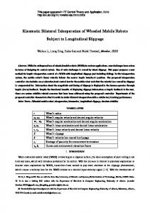
2. INVERSION SCHEMES FOR A PPR ROBOT Consider the PPR planar robot shown in Fig. 1, having one revolute and two prismatic joints. This robot is redundant for the task of positioning the tip of the end-effector in the plane with unspecified orientation (n = 3, rrc = 2). Denoting by the length of the third link, the direct kinematic equations are
has always full row rank. 2.1. A holonomic
inversion scheme
We begin our analysis by identifying all cyclic generalized inverses G = [g, g2] of J, i.e. those kinematic inversion schemes under which arbitrary reconfiguration is not
Figure 1. A PPR planar robot.
253 possible. To this end, note that all generalized be obtained as
inverses of a full rank Jacobian
J can
where G1 is any generalized inverse of J, ni is a vector spanning A((J) and r(q) is an arbitrary vector in R'. For the PPR robot, it is convenient to choose C¡ in (6) as follows. Given a positive-definite matrix
where w is a constant with the same units of is the particular generalized inverse defined as
the W-weighted
pseudoinverse
of J
Note that the weighting factor w2 is introduced for achieving dimensional homogeneity. Therefore, all the generalized inverses of the Jacobian for the PPR robot can be expressed as in (6), where G1 = JW and
Imposing
the involutivity
condition (3), we obtain
with the two-dimensional vector function r(q) as a parameter. cyclic inverses are characterized by r, and r2 in (6) satisfying
For example,
a feasible choice is
Assuming
r = r(q3),
254
In fact, by using (5), the differential inverse (8) is computed as
that can be integrated
constraint
(4) associated
with the generalized
as
where c is a constant depending on the initial conditions. The motion of the PPR robot is constrained to the level surface 1io of h(q) corThe kinematic inversion manifold). responding to q(0) = qo (a two-dimensional scheme corresponding to the generalized inverse (8) is then holonomic. This implies that we cannot reconfigure the arm from qo to an arbitrary qd, unless qd E 1io. On the other hand, whenever the cartesian command u(t) is cyclic with period T, we have necessarily q (T ) = qo. Thus, the generalized inverse (8) gives a cyclic inversion scheme. 2.2. A non-holonomic
inversion scheme
Consider now the kinematic control scheme directly corresponding to the W-weighted pseudoinverse (7), obtained from (6) for C¡ = JW and r = 0. The joint velocities are then obtained as
Denoting by jwl and jwZ the two input vector fields in (9), a simple computation shows that --
It can be readily verified that the above Lie bracket does not belong to span jw2 1. }. In fact, the As a consequence, dim A = n = 3 and system (9) is non-holonomic. associated kinematic constraint computed from (5)
is not integrable. the Since accessibility holds for the PPR arm under weighted pseudoinversion, reconfiguration problem is solvable by a proper choice of ul and U2 in (9). In the next sections we shall present two different solution approaches.
255 3. RECONFIGURATION VIA HOLONOMY ANGLE METHOD A peculiar feature of non-holonomic systems is that if m coordinates are forced to coordinates perform a cyclic motion over a time interval [0, T], the remaining n - m will display a drift at time t = T with respect to their initial values. This drift is often called holonomy angle [15]. In this section, the basic idea is to plan a specific motion for a set of m coordinates so that the holonomy angle matches the value associated to the desired reconfiguration. In order to apply this method to the PPR robot under the weighted pseudoinverse scheme (9), it is convenient to rewrite the system equations in terms of the new set of coordinates (px, p," q3) as
with a = .e/(W2 + .e2). Since this change of coordinates is always invertible, there is a unique configuration (pd, q3d) = (Pxd, Pya, q3d) corresponding to the desired qd. Based on (10), it is straightforward to choose u I and u2 in feedback so as to bring the end-effector position to pd. In particular, by using non-smooth controls, this first phase can be completed in a finite time t¡. Next, it is necessary to transfer the robot from q(tl), the configuration at the end of the first phase, to the final qd. Since p(tl) = pd, this objective can be achieved by moving the end-effector on a closed path r. The resulting drift of the third joint is the holonomy angle
where T is the (arbitrary) duration of the cycle r. In order to have a cyclic Cartesian motion, the integral of the command u(t) should be zero over the time interval [tl, t, + T]. For ease of analysis, a parameterized class of inputs is selected. In the second phase, we need to solve the following problem: given the desired reconfiguration y = q3d - q3(t¡), determine the parameter values in the chosen class of inputs so as to satisfy (11). Accordingly, q, and q2 will move to the desired angles qld and q2d. We note that, since the right-hand side of (10) depends on q3, the system is not in the so-called Caplygin form [13] and the value of y in (11) will depend on the initial value q3(tl)We will consider as input class a sequence of constant velocity commands in which only one input is active at each instant:
256 For a given T, this class is parameterized by A. The path r traced by the robot end-effector will be an xy-square of side A in the counterclockwise direction, located right and above pd for A > 0, or left and below pd for A < 0. For the special case E = w = 1(a = 1/2), the forward integration of the third equation in (10) gives
i.e. q3(tl + T) = q3d, and using the transImposing the desired reconfiguration, formation x = é/2, leads to the following fourth-order polynomial equation to be solved:
Only the real positive roots of (13) are relevant: for a root x > 1, we have A > 0 and an upper right square; for a root 0 < x < 1, A < 0 and a lower left square. Besides, x = 1 (A = 0) is a root only if y = 0 (no reconfiguration needed). This method has been simulated for qo = (1, 1, n/3), qd = (2, 1, 2n/3) and T = 4 s. In this case, the initial end-effector position po coincides with the final end-effector position pd, and the first phase is not necessary. The desired reconfiguration y = n/3 is obtained along a square path of side A = 1.578, corresponding to the solution of (13) with the smallest magnitude. Figures 2 and 3 show the motion of the arm along the square path and the evolution of the joint variables, respectively. The peaks correspond to the sudden changes of the end-effector velocity at the comers of the square path r. We finally note that: . In most cases, the smallest value of A is of interest, so as to obtain the reconfiguration with the smallest end-effector motion. . For some special values of q3(tj ) and q3d, no real root of (13) exists. In these degenerate cases, two or more cyclic motions of the end-effector are needed to It can be proven that this strategy is build up the desired joint reconfiguration. always successful. 0 . Equation (13) can also be used for exploring the existence of a solution such that the holonomy angle y = 0, i.e. q (t, + T) = q (tl ). In other words, even if the kinematic inversion scheme (9) is non-holonomic, there may exist holonomic paths, i.e. particular end-effector cycles along which no drift occurs in the joint The occurrence of such paths is not frequent. For example, in the coordinates. case 2 = 1, it can be shown that no joint configuration is repeatable along squares of side A < 3.52.
257
Figure 2. Reconfigurationof the PPR robot with the holonomy angle method.
Figure 3. Joint evolutionsof the PPR robot with the holonomyangle method: qi(-), yz
(- -), q3 (...).).
4. RECONFIGURATION VIA SINUSOIDALSTEERING A powerful approach to non-holonomic motion planning relies on the existence of canonical forms for which the problem can be efficiently solved. The most common is the so-called chained form [14]. In particular, a two-input system
258 admits a chained-form representation if there exists an invertible state-dependent inx5(x) (a feedback put transformation v = f3 (x) wand a change of coordinates = that transformation) such
In view of the application to the PPR robot, we restrict our attention to the case n = 3. Define the distributions
If, for some open set U C ]R3, we have dim Ao = 3, Ai is exists a smooth function h1: U H M83such that
involutive on U and there
then there exists a feedback transformation (local on U) that puts the system into chained form. 3 II83 In fact, in the above hypotheses, one can find a smooth function h2: U H satisfying so that the change of coordinates
and the input transformation
is
is
where Lgh = g denotes the Lie derivative of h with respect to g. For the PPR robot, it is convenient to use the system representation (10), and to set x = (p,, px, q3) and v = (VI, Uz) _ (u2, ul). Correspondingly, we have
Being
259 it is easy to see that A is involutive. Applying the constructive part of the proof of Frobenius Theorem (see [5, p. 26]) to solve the partial differential equations (16) and (17), a feasible state transformation is obtained as
where il(p,, q3) = COS 2(q3/2) + e2,px sin2(q3/2) =1= 0. The corresponding tion for the original input u in (10) is given by
transforma-
with wl and W2 external inputs to be designed. Indeed, the feedback transformation (18)-(19) is just one possible choice, with the nice feature of being globally defined. The initial configuration qo and the desired configuration qd are mapped through and (18) into respectively. With the robot kinematic control system in chained form, the choice of sinusoidal steering is particularly advantageous, as shown in [14]. The reconfiguration task may be executed in two phases: to their desired values 41d and 42d in a finite (1) Steer the base variables ?l and time tl, using non-smooth feedback laws for w, and w2. The remaining variable will move to (2) Use sinusoidal
open-loop
commands
where t E [tl, tl + T] and T > 0 is arbitrary. In this way, over T returning to their desired values. In order to bring at t = ti + T, the amplitudes are chosen as desired value
This method has been simulated section. The duration of the two this simulation, we have used for The arm is practically still at tl,
and will cycle from $3 (ti ) to its
for the same reconfiguration task of the previous phases is tl = 0.6 s and T = I s, respectively. In simplicity a linear feedback within the first phase. corresponding to 30 times the time constant with
260
Figure 4. Reconfigurationof the PPR robot with sinusoidal steering.
Figure 5. Joint evolutionsof the PPR robot with sinusoidal steering: ql (-), q2 (- -), q3
).
the chosen gains. The resulting motion is shown in Figs 4 and 5. Both joint and end-effector evolutions are smoother than those obtained with the first method. Note that: . As in the holonomy angle method, the first phase is performed in feedback, while the second specifies w(t) in a feedforward mode. However, in both phases the input transformation (19) must be applied in order to obtain the state-dependent actual task command u(t). . Sometimes it is convenient to use multiple sinusoidal phases, each achieving part of the reconfiguration for $3. In this way, it may be possible to limit the required end-effector displacement along the cycle.
261 . While the holonomy angle method prescribes the execution of a cycle over the task coordinates px and p,., in the sinusoidal steering method the cycle takes place over and £2. the transformed base variables
5. CONCLUSION We have shown that the possibility of reconfiguring redundant robots driven only through end-effector commands is related to the non-holonomy of the differential constraints associated with the chosen kinematic inversion scheme. For robots with a single degree of redundancy, accessibility is equivalent to noncyclicity. In this case, two solution approaches have been presented for the reconfiguration problem, based on the established analogy with motion planning for nonholonomic systems. As useful tools, we used the holonomy angle concept and the transformation in chained form. The synthesis of the two control laws was carried Both schemes are nonsmooth out on a PPR robot under weighted pseudoinversion. and prescribe an open-loop phase, and thus are sensitive to numerical approximations or errors in the initial conditions. In the presence of multiple degrees of redundancy, it will be necessary to check the accessibility condition even if cyclicity has already been excluded. In fact, a subset of the differential constraints associated with the chosen kinematic inversion scheme may be integrable. In these intermediate situations, reconfiguration is possible only submanifold of the joint space. within a lower-dimensional While the holonomy angle concept is effective only for robots with a single degree of redundancy, the sinusoidal steering method may be generalized to an arbitrary number of joints and to higher degrees of redundancy by steering with sinusoids at integrally related frequencies, as in [14]. In particular, the results of [16] on the existence of chained forms guarantee that the associated reconfiguration strategy can be applied to any redundant robot with up to n = 4 rotary and/or prismatic joints and m = 2 task inputs, provided that the inverse kinematic scheme is non-holonomic. However, deriving the chained form representation can certainly become a difficult job. Finally, we briefly mention a natural extension of the problem considered in this paper, i.e. reconfigure the arm by using a kinematic inversion scheme that includes a null-space term:
where v(q) is typically chosen as the gradient of a configuration-dependent criterion, from or obstacles The of such a distance [17]. singularities adoption workspace e.g. scheme could be desirable, because reconfiguration is attempted while maintaining a certain degree of control of the joint motion. It can be shown that, provided the chosen generalized inverse G is non-holonomic, it is still possible to drive the robot to a desired joint configuration qd by a proper choice of u in (20). While a proof of this fact is not given here, we wish to emphasize the two following facts:
262 term in (20) represents a drift for the cor. The additional configuration-dependent control net motion with zero input). As a connon-linear (i.e. system responding condition becomes the (2) accessibility only a necessary condition for sequence, to the of small-time local controllability [18], concept controllability. By resorting it is possible to derive a sufficient condition for the solvability of the reconfiguration problem, that is satisfied if G is non-holonomic. . The presence of a drift term must be taken into account also for the a reconfiguration method. While sinusoidal steering cannot be used, system cannot be put in chained form, the holonomy angle method applied, provided that one compensates for the perturbation introduced A detailed discussion of these and related issues may be found in [19].
synthesis of because the can still be by the drift.
Acknowledgements This work is supported by ESPRIT III Basic Research Project 6546 (PROMotion).
REFERENCES 1. Y. Nakamura, AdvancedRobotics: Redundancyand Optimization.Reading, MA: Addison-Wesley, 1991. 2. C. A. Klein and C. H. Huang, "Reviewof pseudoinversecontrol for use with kinematicallyredundant manipulators,"IEEE Trans. Systems,Man, Cybernet.,vol. 13, no. 3, pp. 245-250, 1983. 3. R. M. Murray, Z. Li and S. S. Sastry,A MathematicalIntroduction to Robotic Manipulation. New York:CRC Press, 1994. 4. G. Oriolo, "Stabilizationof self-motionin redundant robots," in Proc. IEEE Int. Conf. on Robotics and Automation,San Diego, CA, 1994, pp. 704-710. 5. A. Isidori, Nonlinear Control Systems.Berlin: Springer-Verlag,2nd edn, 1989. 6. T. Shamir and Y. Yomdin,"Repeatabilityof redundant manipulators: Mathematicalsolution of the problem," IEEE Trans. AutomaticControl, vol. 33, no. 11, pp. 1004-1009, 1988. 7. F. A. Mussa-Ivaldiand N. Hogan,"Integralsolutionsof kinematicredundancyvia impedancecontrol," Int. J. Robotics Res., vol. 10, no. 5, pp. 481-491, 1991. 8. A. De Luca, L. Lanari and G. Oriolo, "Control of redundant robots on cyclic trajectories,"in Proc. IEEE Int. Conf. on Robotics and Automation,Nice, 1992, pp. 500-506. 9. R. G. Roberts and A. A. Maciejewski,"Singularities,stable surfaces, and the repeatable behavior of kinematicallyredundant manipulators,"Int. J. Robotics Res., vol. 13, no. 1, pp. 70-81, 1994. 10. R. G. Roberts and A. A. Maciejewski,"Nearest optimal repeatablecontrol strategiesfor kinematically redundant manipulators,"IEEE Trans. RoboticsAutomat.,vol. 8, no. 3, pp. 327-337, 1992. 11. J. I. Neimark and N. A. Fufaev, Dynamicsof NonholonomicSystems.Translationsof Mathematical Monographs33. Providence:AmericanMathematicalSociety, 1972. 12. R. W. Brockett, "Asymptoticstability and feedback stabilization,"in Differential Geometric Control Theory, R. W. Brockett, R. S. Millmann and H. J. Sussmann, eds, Boston: Birkhäuser, 1983, pp. 181-191. 13. A. M. Bloch, M. Reyhanoglu and N. H. McClamroch,"Control and stabilization of nonholonomic dynamic systems,"IEEE Trans.AutomaticControl, vol. 37, no. 11, pp. 1746-1757, 1992. 14. R. M. Murray and S. S. Sastry, "Nonholonomicmotion planning: Steering using sinusoids," IEEE Trans.AutomaticControl, vol. 38, pp. 700-716, 1993. 15. J. E. Marsden, R. Montgomeryand T. Ratiu, Reduction,Symmetry,and Phases in Mechanics. Providence, RI: Memoirs AMS, vol. 88, no. 436, 1990. 16. R. M. Murray, "Control of nonholonomicsystems using chained form," Fields Inst. Commun.,vol. 1, pp. 219-245, 1993.
263 17. A. Liègeois, "Automaticsupervisorycontrol on the configurationand behavior of multibody mechanisms," IEEE Trans. Systems,Man, Cybernet.,vol. SMC-7, no. 12, pp. 868-871, 1977. 18. H. J. Sussmann, "A general theorem on local controllability,"SIAMJ. Control Optimization,vol. 25, pp. 158-194, 1987. 19. A. De Luca, R. Mattone and G. Oriolo, "Dynamic mobility of redundant robots using end-effector commands," in Proc. IEEE Int. Conf. of Robotics and Automation, Minneapolis, MN, 1996, pp. 1760-1767
ABOUT THE AUTHORS Alessandro De Luca receivedthe Ph.D. in SystemsEngineering,from the Università di Roma 'La Sapienza' in 1987. From Fall 1985 to Spring 1986, he was a Visiting Scholar at the Robotics and Automation Laboratory of the Rensselaer Polytechnic Institute, Troy, NY. From 1989 to 1992 he was a Research Associate and then he became Associate Professor of Automatic Control and Industrial Robotics at the Universitàdi Roma 'La Sapienza', where he currentlyheads the RoboticsLaboratory. He is an Associate Editor of the IEEE Transactionsof Roboticsand Automation. His research interests include non-linear control with applicationsto robotics, modeling and control of manipulators with elastic joints and flexible links, redundant manipulators,hybrid forcevelocity robot control, and non-holonomiccontrol systems. Giuseppe Oriolo received the Laurea degree in Electrical Engineeringin 1987 and the Ph.D. degree in SystemsEngineeringin 1992, both from the Universitàdi Roma 'La Sapienza'. From September 1990 to April 1991 he was a Visiting Scholar at the Center for Robotic Systems and Manufacturingof the University of California at Santa Barbara. Since January 1994, he has been a Research Associate at the Dipartimentodi Informaticae Sistemisticaof the Universitàdi Roma 'La Sapienza', where he is a member of the Robotics Laboratory. His research interests focus on planning and control for robotic systems, including redundant manipulators,mobile and non-holonomicrobots.