1246
IEEE TRANSACTIONS ON IMAGE PROCESSING, VOL. 16, NO. 5, MAY 2007
3-D Model-Based Frame Interpolation for Distributed Video Coding of Static Scenes Matthieu Maitre, Student Member, IEEE, Christine Guillemot, Senior Member, IEEE, and Luce Morin
Abstract—This paper addresses the problem of side information extraction for distributed coding of videos captured by a camera moving in a 3-D static environment. Examples of targeted applications are augmented reality, remote-controlled robots operating in hazardous environments, or remote exploration by drones. It explores the benefits of the structure-from-motion paradigm for distributed coding of this type of video content. Two interpolation methods constrained by the scene geometry, based either on block matching along epipolar lines or on 3-D mesh fitting, are first developed. These techniques are based on a robust algorithm for sub-pel matching of feature points, which leads to semi-dense correspondences between key frames. However, their rate-distortion (RD) performances are limited by misalignments between the side information and the actual Wyner–Ziv (WZ) frames due to the assumption of linear motion between key frames. To cope with this problem, two feature point tracking techniques are introduced, which recover the camera parameters of the WZ frames. A first technique, in which the frames remain encoded separately, performs tracking at the decoder and leads to significant RD performance gains. A second technique further improves the RD performances by allowing a limited tracking at the encoder. As an additional benefit, statistics on tracks allow the encoder to adapt the key frame frequency to the video motion content. Index Terms—Distributed source coding (DSC), distributed video coding (DVC), image-based rendering (IBR), motion-adaptive key frames, point tracking, structure-from-motion (SfM).
I. INTRODUCTION ISTRIBUTED SOURCE CODING (DSC) has gained interest for a range of applications such as sensor networks, video compression, or loss-resilient video transmission. DSC finds its foundation in the seminal Slepian–Wolf [1] and Wyner–Ziv (WZ) [2] theorems. Most Slepian–Wolf and WZ coding systems are based on channel coding principles [3]–[9]. The statistical dependence between two correlated sources and is modeled as a virtual correlation channel analogous to binary symmetric channels or additive white Gaussian noise (AWGN) channels. The source (called the side information)
D
Manuscript received May 10, 2006; revised January 2, 2007. This work was supported in part by the European Commission in the context of the network of excellence SIMILAR and in part by the IST-Discover project. The associate editor coordinating the review of this manuscript and approving it for publication was Dr. Fernando M. B. Pereira. M. Maitre is with the Beckman Institute, University of Illinois at UrbanaChampaign, Urbana, IL 61801 USA (e-mail:
[email protected]). C. Guillemot and L. Morin are with the IRISA, Campus Universitaire de Beaulieu, 35042 Rennes Cedex, France (e-mail:
[email protected]; lmorin@ irisa.fr). Color versions of one or more of the figures in this paper are available at http://ieeexplore.ieee.org. Digital Object Identifier 10.1109/TIP.2007.894272
(called the main is, thus, regarded as a noisy version of signal). Using error correcting codes, the compression of is achieved by transmitting only parity bits. The decoder concatenates the parity bits with the side information and performs error correction decoding, i.e., MAP or MMSE estimation of given the received parity bits and the side information . Compression of video streams can be cast into an instance of side information coding, as shown by Aaron et al. [10]–[12] and Puri and Ramchandran [13]–[15]. These schemes are also referred to as distributed video coding (DVC) systems. A comprehensive survey on distributed video compression can be found in [16]. One key aspect in the performance of the system is the mutual information between the side information and the information being WZ encoded. In current approaches, the side information is generated via motion-compensated frame interpolation, often using block-based motion compensation (BBMC) [16]. Motion fields are first computed between key frames, which may be distant from one another. An interpolated version of these motion fields is then used to generate the side information for each WZ frame. The frame interpolation based on these interpolated motion fields is not likely to lead to the highest possible PSNR, hence, to the highest mutual information between the side information and the WZ encoded frame. To cope with these limitations, BBMC is embedded in a multiple motion hypothesis framework in [16] and [17]. The actual motion vectors are chosen by testing the decoded frames against hash codes or CRCs. Here, we address the problem of side information generation in distributed coding of videos captured by a camera moving in a 3-D static environment with Lambertian surfaces. This problem is of particular interest to specialized applications such as augmented reality, remote controlled robots operating in hazardous environments and remote exploration by drones or planetary probes. Augmented reality applications include scenarios where mobile-phone users would transmit videos of their surroundings in order to get semantic or geographic information in return. We explore the benefits of more complex motion models belonging to the structure-from-motion (SfM) paradigm [18]. These motion models exhibit strong geometrical properties, which allow their parameters to be robustly estimated. Unlike predictive coding, DVC has the advantage of not requiring the transmission of motion model parameters. Therefore, increasing the complexity of motion models, and, thus, their ability to accurately represent complex motions, offers potential gains in mutual information without additional bitrate overheads. When used in computer vision applications, SfM approaches aim at generating visually pleasing virtual views [19]. On the
1057-7149/$25.00 © 2007 IEEE
MAITRE et al.: 3-D MODEL-BASED FRAME INTERPOLATION
other hand, when used in DVC, the objective is to generate intermediate frames (the side information) with the highest PSNR. This requires a reliable estimation of the camera parameters as well as sub-pel precision of the reprojected 3-D model, especially in edge regions where even small misalignments can have a strong impact on the PSNR. In addition, constraints on latency in applications such as video streaming, as well as memory constraints, prevent the reconstruction of the 3-D scene from all the key frames at once, as is usually done in SfM. Instead, a sequence of independent 3-D models is reconstructed from pairs of consecutive key frames. In this paper, we first describe two 3-D model-based frame interpolation methods relying on SfM techniques, one block based and one mesh based, both being constrained by the epipolar geometry. These first approaches suffer from the following limitation. The motion fields associated to the intermediate frames are interpolated with the classical assumption of linear motion between key frames. This creates misalignments between the side information and the actual WZ frames, which have a strong impact on the rate-distortion (RD) performances of the 3-D modelbased DVC solution. This observation led us to introduce two methods to estimate the intermediate motion fields using point tracks, instead of interpolating them. The motion fields are obtained by computing the camera parameters at intermediate time instants. A first technique relies on feature point tracking at the decoder, each frame being processed independently at the encoder. In addition to the key frames, the encoder extracts and transmits a limited set of feature points on each key frame, which are then linked temporally at the decoder. Feature point tracking at the decoder greatly reduces misalignments, hence, increases the side information PSNR, which has a significant impact on the RD performances of the 3-D model-based DVC system. A second technique further improves these RD performances by tracking points at the encoder. The encoder, thus, shares some limited information between frames under the form of intensity patches to construct the tracks sent to the decoder. The latter technique has the additional advantage of giving the encoder a rough estimation of the video motion content, which is sufficient to decide when to send key frames. The problem of key frame selection has already been studied in the context of SfM [20] and predictive coding [21]. However, the approaches described rely on epipolar geometry estimation at the encoder, which DVC cannot afford. An alternative to tracking has been proposed in [22], where the authors advocate the use of statistics on intensities and frame differences. The remainder of the article is organized as follows. Section II presents the estimation of the 3-D model, while Sections III and IV describe the model-based frame interpolation, using the assumption of linear motion in the former and using point tracks in the latter. Finally, Section V presents our experimental results. Preliminary results were presented in [23]. II. THREE-DIMENSIONAL MODEL CONSTRUCTION A. Overview We begin by presenting a codec based on the assumption of linear motion, that is, without point tracking. This codec, called
1247
Fig. 1. Outline of the codec without point tracking (3-D DVC). The proposed codec benefits from an improved motion estimation and frame interpolation (gray boxes).
3-D DVC and outlined in Fig. 1, derives from the DVC codec described in [16] and [24]. At the encoder, the input video is split into groups of pictures (GOP) of fixed size. Each GOP begins with a key frame, which is encoded using a standard intracoder (H.264/AVC, in our case) and then transmitted. The remaining frames (WZ frames) are transformed, quantized, and turbo-encoded. The resulting parity bits are punctured and transmitted. At the decoder, the key frames are decompressed and the side information is generated by interpolating the intermediate frames from pairs of consecutive key frames. The turbo-decoder then corrects this side information using the parity bits. The proposed decoder differs from classical DVC by its novel 3-D model construction and model-based frame interpolation. In this section, we first describe the 3-D model construction, whose overall architecture is presented in Fig. 2. Unlike the SfM techniques it extends, the proposed model construction focuses on the PSNR of the interpolated frames to maximize the quality of the side information. Toward that goal, we present a novel robust correspondence estimation with subpixel accuracy. In particular, correspondences are scattered over the whole frames and are dense in areas of high gradients. Furthermore, the 3-D model construction is robust to quantization noise. After introducing some notation, we shall first describe the camera parameter estimation and then the correspondence estimation. B. Notation We shall use the typesettings , , to denote, respectively, scalars, column vectors, and matrices. In the following, denotes the scalar entry of the vector of a set at time . Likewise for matrices, denotes the scalar entry at row and column, while represents its row vector. denotes the transpose of matrix , the Moreover, column vector obtained by stacking the together and the cross-product operator. The identity matrix shall be denoted and . by and the norms 1 and 2 by, respectively, We shall use homogeneous vectors, where and represent, respectively, a 2-D and a 3-D point. These entities are defined up to scale, i.e., is for any non-null scalar . Without equivalent to loss of generality, the two key frames delimiting the current and GOP are assumed to have been taken at times and are, respectively, denoted by and .
1248
IEEE TRANSACTIONS ON IMAGE PROCESSING, VOL. 16, NO. 5, MAY 2007
Fig. 2. Outline of the 3-D model construction. Camera parameters estimation is performed by the top line blocks. Correspondence estimation is performed by the bottom line blocks.
C. Camera Parameter Estimation We assume here that an initial set of point correspondences is available between the two key frames. It is used to estimate both the camera parameters, e.g., translation and rotation, and the depth associated with each point correspondence. 1) Robust Weak-Calibration: The assumption of static scene introduces a constraint on correspondences given by the following:
We constrain the depths in the new WCS to be bounded by 1 to reduce numerical issues during the bundle adjustand ment detailed later. Assuming that the camera parameters do not undergo large variations between key frames, we look for a as close as possible to the identity matrix and commatrix patible with the fundamental matrix . The optimal vector is under the linear then found by minimizing constraints
(1) where is the so-called fundamental matrix, from which the camera parameters shall be extracted. The robust weak-calibration procedure aims at estimating this fundamental matrix. As an additional feature, it identifies erroneous correspondences. It consists of three steps: and the set of inliers using 1) an initial estimation of MAPSAC [25]; and the set of inliers using 2) a first refinement of LO-RANSAC [26]; 3) a second refinement of over the final set of inliers by a nonlinear minimization of the Sampson distance [18]. 2) Quasi-Euclidean Self-Calibration and Triangulation: The next step is to recover the projection matrices and the depths . We choose the World Coordinate System (WCS) of , the 3-D scene to be the camera coordinate system at time . This leaves four degrees of freedom in the leading to WCS. They appear in the relation between and the projection matrix of the second key frame , given by
(4) is given by A lower bound on the value of . The self-calibration starts with this value and increases it until the linear programming problem admits a solution. 3) Bundle Adjustment: The camera parameters and the depths obtained so far are refined by minimizing their euclidean reprojection error on the key frames. First, the basis of the projective space has to be fixed to prevent it from drifting. This is done by fixing two 3-D points and performing the optimization over a reduced parameter space. As shown in Appendix I, can be expressed as a linear the 12-D projection matrix combination of an 8-D unit vector , i.e., where is an orthonormal matrix. The minimization of the euclidean reprojection error is defined as
such that and
(5)
(2) where
where is an arbitrary 3-vector and has an arbitrary norm. For the time being, these degrees of freedom are fixed by with unit norm and setting , where the choosing and are recovered from the singular value epipoles decomposition (SVD) of the matrices and , respectively [18]. Since the projection matrices are defined up-to-scale, they . are normalized so that their Frobenius norm will be The depths are then recovered. Let a 2-D point be the projection of a 3-D point on the camera image plane. These two where is the projective depth. points are related by Therefore, correspondences allow the recovery of a cloud of 3-D points by triangulation, solving the system of equations (3) for each correspondence. The initial choice of WCS is refined by quasi-euclidean selfcalibration [27] so that the WCS is as euclidean as possible.
is the euclidean reprojection error given by
(6) The minimization is solved using the alternated reweighted linear least square approach detailed in Appendix II. D. Correspondence Estimation We now turn to the estimation of the set of point corresponbetween the two key frames. dences are de1) Feature Point Detection: First, feature points tected on each key frame independently. We use the Harris– Stephen corner detector [28] to find feature points. Its sensitivity
MAITRE et al.: 3-D MODEL-BASED FRAME INTERPOLATION
is adapted locally to spread feature points over the whole frame [18], which improves the weak calibration detailed previously. 2) Feature Point Matching: Feature points are then matched across key frames to form correspondences. All pairs of feature points are considered as candidate correspondences. A first series of tests eliminates blatantly erroneous correspondences. 1) Correspondences with very large motion are discarded. 2) Correspondences with dissimilar intensity distributions in the neighborhoods around feature points are discarded. Distributions are approximated using Parzen windows [29, Section 4.3] and sampled uniformly to obtain histograms. -test The similarity of histograms is tested using the [30, Section 14.3]. 3) Subpixel Refinement: The locations of the remaining correspondences are then refined locally by searching for the least mean-square error (MSE) between neighborhoods around feature points. The minimization is solved using the Levenberg–Marquardt algorithm [30, Section 15.5]. This refinement compensates for errors from the Harris–Stephen detector and computes feature point locations with subpixel accuracy. 4) Outlier Removal: A second series of tests is applied to eliminate erroneous correspondences. These tests are performed as soon as the camera parameter estimation provides the relevant information, as shown by the workflow in Fig. 2. 1) Correspondences with large MSE are discarded. 2) Each feature point is only allowed to belong to at most one correspondence. This unicity constraint is enforced using the Hungarian algorithm [31, Section I.5], which keeps only the correspondences with the least MSE when the unicity constraint is violated. 3) Correspondences identified as outliers during the robust weak-calibration are discarded. 4) Correspondences with aberrant motion are removed by testing the difference between their motion and the weighted median of the motions of their neighbors positioned on Delaunay triangles [32, Chap. 9]. Neighbors are assigned weights inversely proportional to their distances. 5) Correspondences with large reprojection errors are discarded. 6) Correspondences for which the sign of the product of prois different from the majority are jective depths removed [33, Th. 17]. 7) Correspondences too close to the epipoles are discarded, to avoid ill-conditioned triangulation equations. 8) Correspondences with aberrant depths compared to the depths of their neighbors are removed. 5) Correspondence Propagation: The set of correspondences obtained so far is reliable and accurate but still fairly sparse. It is first densified over unmatched feature points by increasing the tolerance of the tests described previously and enforcing motion smoothness using the weighted median of neighboring motions. Correspondences are then propagated along edges, under the epipolar constraint. The goal of this procedure is to get accurate motion information in edge regions, where even a slight misalignment can lead to large MSE, degrading the side information PSNR.
1249
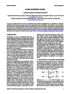
Fig. 3. Correspondences and epipolar geometry between the two first lossless key frames of the sequences street and stairway. Feature points are represented by red dots, motion vectors by magenta lines ending at feature points, and epipolar lines by green lines centered at the feature points. (a) Epipolar geometry after robust weak calibration. (b) Correspondences after propagation along edges. TABLE I THRESHOLDS USED IN THE TESTS FOR OUTLIER REMOVAL
Edges are found in the first key frame using the Canny edge detector [34]. Correspondences are propagated along edges, starting from correspondences between the feature points. At each iteration, edge points around previously known correspondences are selected and their motions are initialized to those of their nearest neighbors. Their motions are then improved by full search over small windows along associated epipolar lines, minimizing the MSE between intensity neighborhoods. Their motions are finally refined by a Golden search [30, Section 10.1] to obtain subpixel accuracy. The robustness of this procedure is increased by removing edge-points too close to the epipole, as well as those whose edge tangents are close to epipolar lines or which have large MSE. E. Results Fig. 3(a) and (b) shows the correspondences obtained between the first two key frames of the sequences street and stairway after, respectively, robust weak-calibration and correspondence propagation. The parameters used for outlier removal are summarized in Table I. In both cases, the epipolar geometry was correctly recovered and correspondences are virtually outlier-free. Moreover, propagation greatly increases
1250
IEEE TRANSACTIONS ON IMAGE PROCESSING, VOL. 16, NO. 5, MAY 2007
the correspondence density, from 394 correspondences to 9982 for the street sequence and from 327 correspondences to 6931 for the stairway sequence. These figures also underline some intrinsic limitation of the SfM approach. First, the street sequence has epipoles inside the images, as can be seen by the converging epipolar lines. Since triangulation is singular around the epipoles, there are no correspondences in their neighborhoods. Second, the stairway sequence contains strong horizontal edges whose tangents are nearly parallel to the epipolar lines. This explains why so few correspondences are found in this region. III. THREE-DIMENSIONAL MODEL-BASED INTERPOLATION The frame interpolation methods developed in this paper rely on the projection of the 3-D scene onto camera image planes. This projection requires the knowledge of the projection matrices associated with the interpolated frames, as well as the knowledge of a dense motion field between the frame being interpolated and each of the two key frames. We consider two motion models to obtain dense motion fields from the correspondences and the projection matrices: one block based and one mesh based, both being constrained by the epipolar geometry. A. Projection-Matrix Interpolation The projection matrices at intermediate time instants are recovered by generalizing the bundle-adjustment equation (5) to three or more frames
such that
(7)
are independent In this equation, the projection matrices of one another given the depths. They are, therefore, solutions of simple reweighted linear least square problems. of the feature points on the intermeSince the locations diate frames are unknown to the decoder, they are interpolated by assuming linear motion, that is (8) Section IV shall present two other codecs which make use of additional information from the encoder to avoid this assumption. B. Frame Interpolation Based on Epipolar Blocks In the first motion model, each intermediate frame is divided into blocks whose unknown texture is to be estimated. The search space of the motion vectors is limited by the epipolar constraint and trifocal transfer [35]. As shown in Fig. 4, given a in the intermediate frame, its corresponding block located at and blocks in the key frames lie along the epipolar lines . For a given candidate location in a reference key frame, say in , the location of the corresponding block in the is uniquely defined via trifocal transfer: other key frame
Fig. 4. Trifocal transfer for frame interpolation based on epipolar blocks.
Fig. 5. Outline of the frame interpolation based on epipolar blocks.
Using (3) with and gives the 3-D point , which is to give as . then projected onto The key frame whose optical center is the furthest away from the optical center of the interpolated frame is chosen as the reference key frame so that the equations of trifocal transfer are best conditioned. As outlined in Fig. 5, the algorithm initializes the motions of the blocks using the motions of the nearest correspondences. It then refines them by minimizing the MSE of the block textures in the key frames, using a local full search along the epipolar lines, followed by a Golden search [30, Section 10.1] to obtain subpixel accuracy. Since trifocal transfer is singular around epipoles, the motions of the blocks too close to the epipoles are not refined. Finally, the block textures from the key frames are linearly blended with weights based on time instants to obtain the texture of the block in the interpolated frame. C. Frame Interpolation Based on 3-D Meshes In the second motion model, the first key frame is divided into blocks which are themselves subdivided into pairs of triangles, thus forming a triangular mesh. Each vertex is associated with , one in each key frame. Due to two locations the epipolar geometry, the second location is constrained to lie on an epipolar line such that (9) where is a line tangent vector, a point on the epipolar line and a scalar. All these quantities are stacked together to form a matrix and two vectors and . Likewise, the point correspondences obtained in Section II are stacked into two loand . Equation (9) rewrites cation vectors (10)
MAITRE et al.: 3-D MODEL-BASED FRAME INTERPOLATION
1251
Fig. 6. Outline of the frame interpolation based on 3-D meshes.
As outlined in Fig. 6, the mesh is first fitted to the set of correspondences. Mesh fitting is cast into a minimization problem using a Tikhonov regularization approach [36]. The motion inside each triangle is assumed to be affine, which approximates the projection of a piecewise-planar 3-D mesh. Therefore, the motion of any point in the first key frame can be written as a linear combination of the motions of the mesh vertices. Let us represent these linear combinations by the , such that . The mesh also has an matrix internal smoothness, which favors small differences between the motion of a vertex and the average motion of its four neighbors. Since the average is a linear operation, it can be represented by a matrix . Let be a scalar controlling the smoothness of the mesh, set to 0.5 in the experiments. The minimization problem is then
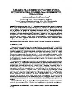
Fig. 7. Norm of the motion vectors between the first two lossless key frames of the stairway sequence for (a) epipolar block matching, (b) 3-D mesh fitting, and (c) classical block matching.
IV. THREE-DIMENSIONAL MODEL-BASED INTERPOLATION WITH POINT TRACKING A. Rationale
(11) This is a linear least-square (LLS) problem, which can readily be solved. Since LLS is not robust to outliers, an additional step removes them. Outliers are detected by testing whether the mesh triangles abide by these two criteria: 1) they must have the same orientation in both key frames; 2) the motion compensation errors must be small. Correspondences inside triangles failing these tests are considered outliers. They are removed and the mesh is fitted again. This process is iterated until all triangles pass the tests. Finally, the mesh is reprojected onto intermediate frames using trifocal transfer. The key frames are warped using 2-D texture mapping [37] and linearly blended. D. Comparison of the Motion Models Epipolar block motion fields approximate well depth discontinuities but only provide a fronto-parallel approximation of the 3-D surfaces. On the other hand, mesh-based motion fields are able to approximate 3-D surfaces with any orientation and are more robust to outliers due to their internal smoothness. At the same time, they tend to over smooth depth discontinuities and they do not model occlusions. These properties are clearly visible in Fig. 7, which shows the norm of the motion vectors on the stairway sequence. This figure also displays the motion field obtained using a classical 2-D block-based motion estimation minimizing the sum of absolute differences (SAD) at integer locations. In comparison, both proposed motion estimations exhibit a reduced number of outliers.
As will be shown in the experimental result section, the above 3-D model-based interpolation techniques barely increase the PSNR of the side information. This comes from the underlying assumption that the tracks have linear motion (8) during the estimation of the intermediate projection matrices (7), which gives inaccurate projection matrices. Since the motion fields are obtained by projecting 3-D points or a 3-D mesh onto image planes, inaccurate projection matrices lead to misalignments between the interpolated frames and the actual WZ frames. These misalignments then create large errors in regions with textures or edges, which penalizes the PSNR. Instead of interpolating correspondences to obtain tracks, it is proposed here to detect actual tracks from the original frames. The linear motion assumption represented by (8) is, thus, not used anymore. We propose two methods to achieve this goal: one tracking points at the decoder and one tracking them at the encoder. In both methods, a set of feature points is extracted at the encoder with a Harris–Stephen feature-point detector [28]. When the tracking is performed at the decoder, the set of feature points is encoded and transmitted to the decoder. When the tracking is done at the encoder, a list of tracked positions per feature point is encoded and transmitted. Unlike previous works [16], [17], no information is sent about the actual intensities of the WZ frames. Computing and transmitting the feature points or tracks introduces overheads on the encoder complexity and on the bandwidth. However, these overheads are minor because only a small number of feature points is required to estimate the eleven parameters of each intermediate projection matrix. Moreover, in the case of tracking at the encoder, statistics on tracks allow the encoder to select key frames based on the video motion content, thus increasing bandwidth savings.
1252
Fig. 8. Outline of the codec with tracking at the decoder (3-D DVC-TD).
B. Tracking at the Decoder This codec, called 3-D DVC-TD, builds upon the 3-D DVC solution based on the frame interpolation techniques presented in Section III, and includes in addition a Harris–Stephen featurepoint detector [28], a feature point encoder and a point tracker at the decoder (see Fig. 8). The set of feature points is encoded and transmitted as a list, , by defined for each time instant t as scanning the image column by column. Due to the chosen scanning order, the horizontal component of the feature-point coordinates varies slowly, so it is encoded using differential pulse code modulation (DPCM) followed by arithmetic coding. On the other hand, the vertical component varies rapidly and is encoded using fixed-length codes. The decoder receives these points and matches them to form tracks. It starts by matching points between key frames using three constraints: the epipolar geometry, motion smoothness with previously matched correspondences and the MSE. It then creates temporal snakes [38] between key frames, with one control point at each time instant. It initializes them assuming a linear motion and optimizes them to fit the set of received points. The optimization procedure solves a LLS problem with equations similar to the ones of mesh fitting (11). To make it more robust to outliers, points are given weights which decrease as the square of their distance to the snakes. The final locations of the snake control points define the tracks in (7). C. Tracking at the Encoder This codec, called 3-D DVC-TE, extends the 3-D DVC solution presented in Section III by adding at the encoder the Harris–Stephen feature-point detector [28], a point tracker and a point-track encoder (see Fig. 9). Therefore, unlike the two previous codecs, some information is shared between the frames. The encoder detects feature points on the current key frame and tracks them in the following frames. Tracking relies on the minimization of SAD between small blocks around point tracks. The minimization only considers integer pixel locations and is biased toward small motions to avoid the uncertainty due to large search regions. It begins by a spiral search around the location with null motion. Once a small SAD is detected, it continues by following the path of least SAD, until a local minimum is found. Tracks for which no small SAD can be found are discarded.
IEEE TRANSACTIONS ON IMAGE PROCESSING, VOL. 16, NO. 5, MAY 2007
Fig. 9. Outline of the codec with tracking at the encoder (3-D DVC-TE).
Tracking is used to select the key frames based on the following two stopping criteria: either the longest track becomes too long or the number of lost tracks becomes too large. In the experiments, the thresholds are set, respectively, to 20px and 75%. The former criterion enforces that key frames sufficiently differ from one another, while the latter criterion ensures that the estimation of intermediate projection matrices is always a well-posed problem. Once a stopping criterion is met, a new key frame is transmitted and the process is reiterated. in the first For each feature point at location key frame, a list of tracked positions is encoded using DPCM followed by arithmetic coding and transmitted. The decoded tracks define in (7). V. EXPERIMENTAL RESULTS We have assessed the performance of the 3-D DVC incorporating the two interpolation methods based on the SfM paradigm as well as the variants of this codec augmented with the feature point tracking either at the encoder (3-D DVC-TE) or at the decoder (3-D DVC-TD). These codecs have been implemented by replacing the frame interpolation of the 2-D DVC codec [24] and adding point tracking. The key frame frequency was estimated automatically in 3-D DVC-TE and set to one key frame every ten frames in 3-D DVC and 3-D DVC-TD, which introduces a delay of about one third second. Experimental results are presented on three sequences: street, stairway and statue. They correspond to augmented reality applications. The first two, shown in Fig. 3, are CIF at 30 Hz with 50 frames. The third one, shown in Fig. 10, is CIF 25 Hz with 50 frames. These sequences contain drastically different camera motions, as can be seen from the motion vectors and the epipolar geometries. In the first one, the camera has a smooth motion, mostly forward. In the second one, the camera has a lateral translational motion with hand jitter, creating motions of up to 7 pixels between consecutive frames. In the last one, the camera has a lateral rotational motion with hand jitter, which creates a large occlusion area around the statue. A. Frame Interpolation Without Tracking (3-D DVC) In DVC, the key frames are first quantized and encoded. It is, thus, essential to assess the performance of the different techniques designed in this context. Fig. 10 shows that the 3-D model estimation behaves well even with coarsely quantized key
MAITRE et al.: 3-D MODEL-BASED FRAME INTERPOLATION
Fig. 10. Correspondences and epipolar geometry between the two first key frames of the sequence statue. Feature points are represented by red dots, motion vectors by magenta lines ending at feature points, and epipolar lines by green lines centered at the feature points. (a) Lossless key frames; (b) quantized key frames (QP = 42).
1253
Fig. 12. Correlation noise for GOP 1, frame 5 (center of the GOP) of the stairway sequence, using lossless key frames: (a) 2-D DVC with classical block matching, (b) 3-D DVC with mesh model and linear tracks, (c) 3-D DVC-TE with mesh model and tracking at the encoder, and (d) 3-D DVC-TD with mesh model and tracking at the decoder . The correlation noise is the difference between the interpolated frame and the actual WZ frame. TABLE II AVERAGE PSNR (IN DECIBELS) OF INTERPOLATED FRAMES USING LOSSLESS KEY FRAMES
the interpolation process does not have a significant impact on the PSNR of the interpolated frames compared to classical block matching. This can be explained by the fact that the resulting interpolated motion fields create misalignments between the side information and WZ frames (see Fig. 12). We will see in Section V-D that this translates into poor RD performances of the 3-D DVC solution. B. Frame Interpolation With Tracking at the Encoder (3-D DVC-TE)
Fig. 11. PSNR of interpolated frames, without parity-bit correction, using lossless key frames (from top to bottom: sequences street, stairway, and statue). Missing points correspond to key frames (infinite PSNR).
frames. The motion vectors and the epipolar geometries for the remain similar to intraframe quantization parameter those of lossless coding, the major difference lying in the density of correspondences. Fig. 11 shows the PSNR of the interpolated frames obtained with the different interpolation methods. As for 3-D DVC, the only introduction of the epipolar or 3-D geometry constraints in
Fig. 11 shows that 3-D frame interpolation aided by point tracks consistently outperforms both 3-D frame interpolation without point tracks (3-D DVC) and classical 2-D block matching (2-D DVC), bringing at times improvements of more than 10 dB. This results from the fact that misalignments between the side information and WZ frames are greatly reduced by estimating the intermediate projection matrices from actual tracks, instead of assuming linear track motion (see Fig. 12). Table II summarizes the average PSNR of the different interpolation methods. It shows that, when used jointly with the feature point tracking to correct misalignments, the mesh-fitting interpolation method is superior to the epipolar block-based method in both sequences, bringing average PSNR gains up to 0.7 dB.
1254
IEEE TRANSACTIONS ON IMAGE PROCESSING, VOL. 16, NO. 5, MAY 2007
Fig. 13. PSNR of key frames and interpolated frames, without parity-bit correction, of the street sequence using 3-D DVC-TE with mesh fitting on lossy key frames. Peaks correspond to key frames.
Fig. 14. Comparison of the subjective quality and the correlation noise between (a) a key frame and (b) an interpolated frame, using key frames quantized at QP = 26. In spite of a PSNR drop of 8.1 dB, both frames have a similar subjective quality. (a) Zoom on frame 1 (PSNR: 36.5 dB); (b) zoom on frame 5 (PSNR: 28.4 dB).
Tracking has two drawbacks: it introduces a bit-rate overhead and increases the coder complexity. The bit-rate overhead represents less than 0.01b/pixel. Compared to classical 2-D BBMC coders, the complexity overhead is very limited due to the small number of tracks. Assuming 8 8 blocks for 2-D BBMC, a CIF blocks. On the other hand, frame has the average number of tracks is 128. Therefore, the complexity of the proposed tracking is only 8% of a 2-D BBMC. Fig. 13 shows the robustness of the proposed frame interpolation to quantization noise, the quality of the interpolated frames degrading gracefully as the bitrate is decreased. Unlike in quantization, where a larger quantization step size decreases both the bitrate and the PSNR, this was not a straightforward result in frame interpolation, where a larger bitrate does not necessarily imply a larger PSNR. This figure also shows that the PSNR of interpolated frames actually decreases more slowly than the one of key frames. Since quantization reduces the high-frequency content of the key frames, it reduces the impact of interpolation misalignments. It also reduces the impact of the low-pass effects of warping, both spatial and temporal. The PSNR of interpolated frames has a ceiling value at about 30 dB. It is quickly attained as the QP of key frames is decreased: this PSNR is about the same whether key frames are . losslessly encoded or quantized at Finally, although the objective quality strongly peaks at key frames, the subjective quality is nearly constant in the street sequence, as illustrated in Fig. 14. Both sources of errors, misalignments and low-pass effects, are barely noticeable. This does not mean, however, that they are not a limiting factor of the codec overall performances because parity bits correct objective errors, not subjective ones. The subjective quality also remains stable in the stairway sequence and statue sequences, except in the occlusion area around the statue where the frame interpolation introduces noticeable artifacts.
Fig. 15. Rate-distortion curves for H.264/AVC intra, H.264/AVC inter-IPPP with null motion vectors, H.264/AVC inter-IPPP, 2-D DVC I-WZ-I and the three proposed 3-D codecs (top left: street; top right: stairway; bottom: statue).
C. Frame Interpolation With Tracking at the Decoder (3-D DVC-TD) Figs. 11 and 12 show that point tracking at the decoder is also able to greatly reduce misalignments and to consistently outperform 2-D DVC and 3-D DVC. PSNR values obtained by 3-D DVC-TD are nearly constant inside each GOP on the street sequence. The superiority of tracking at the encoder (3-D DVC-TE) is, in part, due to the possibility of inserting new key frames and restarting tracking in case of difficult motions. Like in the 3-D DVC-TE case, overheads are also limited. An average of 176 feature points are detected at the encoder, which leads to a bitrate overhead of 0.02b/pixel. The complexity is similar to the one of intracoding. D. Rate-Distortion Performances Fig. 15 compares the rate-distortion performances of the proposed mesh-based codecs, the 2-D DVC codec [24] upon which they are based and the H.264/AVC reference software version JM 9.6. The proposed codecs only differ from the 2-D DVC codec by their side information generation, the 2-D DVC codec relying on an advanced 2-D block-based motion estimation designed specifically for DVC. In all the DVC codecs, the key frames are coded using H.264/AVC intra. The 2-D DVC software has GOPs I-WZ-I, while H.264/AVC is tested in three modes: pure intra, inter-IPPP with motion search and IPPP with null motion vectors. The 3-D codecs with alignment (3-D DVC-TD and 3-D DVC-TE) strongly outperform the 3-D codec without alignment (3-D DVC), confirming the need for precise motion alignment.
MAITRE et al.: 3-D MODEL-BASED FRAME INTERPOLATION
1255
Compared to 2-D DVC, 3-D DVC-TE is superior over the whole range of bitrates on all sequences, while 3-D DVC-TD is superior on the street sequence over the whole range of bitrates, on the stairway sequence up to 990 kb/s and on the statue sequence up to 740 kb/s. Note, however, that this RD gain was achieved at the expense of the generality of the codec, 2-D DVC being able to handle sequences with generic 2-D motion. Finally, compared to H.264/AVC, both 3-D codecs with alignment outperform intracoding and underperform intercoding with motion search. Since 3-D DVC-TE benefits from a limited interframe information at the encoder, it is also compared to H.264/AVC with intercoding without motion search. The 3-D codec is superior for bitrates up to 890 kb/s on the street sequence, over the whole range of bitrates on the stairway sequence and up to 1.4 Mb/s on the statue sequence.
and their projections. We would like two points . The two points to obtain a minimum parameterization of , four of which are independent. induce six constraints on Each point is associated with an equation of the form . Using the third component to solve for , we obtain and . These equations where is defined as can be rewritten as
VI. CONCLUSION
where , , and are three matrices. Therefore, the projeccan be parameterized by a vector such that tion matrices .
In this paper, we have explored the benefits of the SfM paradigm for distributed coding of videos of static scenes captured by a moving camera. The SfM approach allows introducing geometrical constraints in the side information generation process. We have first developed two frame interpolation methods based either on block matching along epipolar lines or 3-D mesh fitting. These techniques make use of a robust feature-point matching algorithm leading to semi-dense subpixel correspondences between pairs of consecutive key frames. The resulting interpolated motion fields show a reduced number of outliers compared with motion fields obtained from 2-D blockbased matching. It has been observed that this property does not translate into significant side information PSNR gains, because of misalignments problems between the side information and the WZ encoded frames. This limitation has been overcome by estimating the intermediate projection matrices from point tracks obtained either at the encoder or at the decoder. It has led to major side information PSNR improvements with only limited overheads, both in terms of bitrate and encoder complexity. As an additional feature, point tracking at the encoder enables a rough estimation of the video motion content, which is sufficient to select the key frames adaptively. The RD performance of the three DVC schemes has been assessed against several state-ofthe-art methods, showing the benefits of the 3-D model-based interpolation methods augmented with feature point tracking for the type of application and content considered. An interesting issue would be to extend the proposed frame interpolation techniques to videos with more generic motion fields and to assess such methods against solutions in which limited motion search would be considered at the encoder. APPENDIX I FIXING THE PROJECTIVE BASIS During the nonlinear optimization of projection matrix , and choosing the projective basis is fixed by setting
(12)
Taking the SVD of
gives (13)
APPENDIX II BUNDLE ADJUSTMENT The bundle adjustment problem given by (5) is solved using an alternated reweighted linear least square approach. First, the denominators are factored out and treated as constant weights, only updated at the end of each iteration. These weights, denoted , are defined as (14) and initialized to 1. The problem then becomes biquadratic in its parameters
such that
(15)
which is solved by alternatively fixing either the projective or the camera parameters and minimizing depths over the free parameters. are fixed, the problem is When the projective depths equivalent to finding the unit-norm vector which minimizes the squared norm of , where matrix is obtained by stacking together submatrices of the form in (16), shown at the bottom of the page. The solution is obtained by taking the SVD of matrix and choosing the vector with the smallest singular value.
(16)
1256
IEEE TRANSACTIONS ON IMAGE PROCESSING, VOL. 16, NO. 5, MAY 2007
When the camera parameters are fixed, the problem is unconstrained and its Hessian is diagonal. Taking the derivative and setting it to 0 leads to the with regard to a particular solution
where
(17)
ACKNOWLEDGMENT The authors would like to thank the anonymous reviewers, as well as the Associate Editor, for their time and effort and their helpful comments. The authors would also like to thank the IST development team for its original work on the IST-WZ codec [24] and the Discover software team for the improvements they provided. REFERENCES [1] J. Slepian and J. Wolf, “Noiseless coding of correlated information sources,” IEEE Trans. Inf. Theory, vol. IT-19, no. 4, pp. 471–480, Apr. 1973. [2] A. Wyner and J. Ziv, “The rate-distortion function for source coding with side information at the decoder,” IEEE Trans. Inf. Theory, vol. IT-22, no. 1, pp. 1–10, Jan. 1976. [3] S. Pradhan and K. Ramchandran, “Distributed source coding using syndromes (discus): Design and construction,” IEEE Trans. Inf. Theory, vol. 49, no. 3, pp. 626–643, Mar. 2003. [4] A. Aaron and B. Girod, “Compression with side information using turbo codes,” presented at the IEEE Int. Data Compression Conf., 2002. [5] J. Garcia-Frias and Y. Zhao, “Compression of correlated binary sources using turbo codes,” IEEE Comm. Lett., vol. 5, no. 10, pp. 417–419, Oct. 2001. [6] ——, “Data compression of unknown single and correlated binary sources using punctured turbo codes,” in Proc. Allerton Conf., 2001. [7] J. Bajcsy and P. Mitran, “Coding for the Slepian–Wolf problem with turbo codes,” in Proc. IEEE Int. Global Communication Conf., 2001, pp. 1400–1404. [8] A. Liveris, Z. Xiong, and C. Georghiades, “Compression of binary sources with side information at the decoder using LDPC codes,” IEEE Comm. Lett., vol. 6, no. 10, pp. 440–442, Oct. 2002. [9] T. Tian, J. Garcia-Frias, and W. Zhong, “Compression of correlated sources using ldpc codes,” presented at the IEEE Int. Data Compression Conf., 2003. [10] A. Aaron, R. Zhang, and B. Girod, “Wyner–Ziv coding of motion video,” presented at the Asilomar Conf. Signals, Systems, Computer, 2002. [11] A. Aaron, S. Rane, R. Zhang, and B. Girod, “Wyner–Ziv coding for video: Applications to compression and error resilience,” in Proc. IEEE Int. Data Compression Conf., 2003, pp. 93–102. [12] A. Aaron, S. Rane, E. Setton, and B. Girod, “Transform-domain Wyner–Ziv codec for video,” presented at the SPIE Conf. Visual Communication and Image Processing, 2004. [13] R. Purit and K. Ramchandran, “PRISM: A new robust video coding architecture based on distributed compression principles,” presented at the Allerton Conf., 2002. [14] R. Purit and K. Ramchandran, “PRISM: A new reversed multimedia coding paradigm,” presented at the Int. Conf. Image Processing, 2003. [15] R. Puri, A. Majumbar, P. Ishwar, and K. Ramchandran, “Distributed video coding in wireless sensor networks,” Signal Process., vol. 23, pp. 94–106, 2006. [16] B. Girod, A. Aaron, S. Rane, and D. Rebollo-Monedero, “Distributed video coding,” Proc. IEEE, vol. 93, no. 1, pp. 71–83, Jan. 2005.
[17] P. Ishwar, V. Prabhakaran, and K. Ramchandran, “Towards a theory for video coding using distributed compression principles,” presented at the Int. Conf. Image Processing, 2003. [18] Y. Ma, S. Soatto, J. Kosecka, and S. Sastry, An Invitation to 3D Vision. New York: Springer-Verlag, 2004. [19] C. Zitnick, S. Kang, M. Uyttendaele, S. Winder, and R. Szeliski, “Highquality video view interpolation using a layered representation,” presented at the ACM SIGGRAPH, 2004. [20] J. Repko and M. Pollefeys, “3D models from extended uncalibrated video sequences: Addressing key-frame selection and projective drift,” presented at the 3-D Digital Imaging and Modeling, 2005. [21] F. Galpin and L. Morin, “Sliding adjustment for 3D video reprensentation,” EURASIP J. Appl. Signal Process., vol. 2002, no. 10, pp. 1088–1101, 2002. [22] J. Ascenso, C. Brites, and F. Pereira, “Content adaptive Wyner–Ziv video coding driven by motion activity,” presented at the Int. Conf. Image Processing, 2006. [23] M. Maitre, C. Guillemot, and L. Morin, “3D scene modeling for distributed video-coding,” presented at the Int. Conf. Image Processing, 2006. [24] J. Ascenso, C. Brites, and F. Pereira, “Improving frame interpolation with spatial motion smoothing for pixel domain distributed video coding,” presented at the EURASIP Conf. SIPMCS, 2005. [25] P. Torr and A. Zisserman, “Robust computation and parametrization of multiple view relations,” presented at the Int. Conf. Computer Vision, 1998. [26] O. Chum, J. Matas, and J. Kittler, “Locally optimized ransac,” presented at the 25th DAGM Symp., 2003. [27] Beardsley, Zisserman, and Murray, “Sequential updating of projective and affine structure from motion,” Int. J. Comput. Vis., vol. 23, pp. 235–259, 1997. [28] C. Harris and M. Stephens, “A combined corner and edge detector,” in Proc. Alvey Vision Conf., 1988, pp. 147–151. [29] R. Duda, P. Hart, and D. Strok, Pattern Classification, 2nd ed. New York: Wiley, 2001. [30] W. Press, B. Flannery, S. Teukolsky, and W. Vetterling, Numerical Recipes in C: The Art of Scientific Computing. Cambridge, U.K.: Cambridge Univ. Press, 1993. [31] D. Luenberger, Linear and Nonlinear Programming, 2nd ed. Norwell, MA: Kluwer, Aug. 2003. [32] M. Berg, M. Kreveld, M. Overmars, and O. Schwarzkopf, Computational Geometry: Algorithms and Applications, 2nd ed. New York: Springer-Verlag, 2000. [33] R. Hartley, “Chirality,” Int. J. Comput. Vis., vol. 26, no. 1, pp. 41–61, 1998. [34] D. A. Forsyth and J. Ponce, Computer Vision: A Modern Approach. Englewood Cliffs, NJ: Prentice-Hall, 2002. [35] R. Hartley, “Lines and points in three views and the trifocal tensor,” Int. J. Comput. Vis., vol. 22, no. 2, pp. 125–140, 1997. [36] S. Boyd and L. Vandenberghe, Convex Optimization. Cambridge, U.K.: Cambridge Univ. Press, 2004 [Online]. Available: http://www.stanford.edu/~boyd/cvxbook.html [37] M. Woo, J. Neider, T. Davis, and Shreiner, OpenGL Programming Guide, 3rd ed. Reading, MA: Addison Wesley, 1999. [38] C. Xu and J. L. Prince, “Snakes, shapes, and gradient vector flow,” IEEE Trans. Image Process., vol. 7, no. 3, pp. 359–369, Mar. 1998.
Matthieu Maitre (S’01) received the diplôme d’ingénieur from the Ecole Nationale Superieure des Telecommunications, Paris, France, in 2002, and the M.Sc. degree from the University of Illinois at Urbana-Champaign, Urbana, where he is currently pursuing the Ph.D. degree in the Department of Electrical and Computer Engineering. His research interests include computer vision, image analysis, stereovision, and video compression.
MAITRE et al.: 3-D MODEL-BASED FRAME INTERPOLATION
Christine Guillemot (M’93–SM’04) received the Ph.D. degree from the Ecole Nationale Superieure des Telecommunications (ENST), Paris, France. She is currently Directeur de Recherche at INRIA, in charge of the TEMICS research group dealing with image modelling, processing, video communication, and watermarking. From 1985 to October 1997, she was with FRANCE TELECOM/CNET, where she was involved in various projects in the domain of coding for TV, HDTV, and multimedia applications, and where she coordinated a few (e.g., the European RACE-HAMLET project). From January 1990 to mid-1991, she was with Bellcore as a Visiting Scientist. Her research interests are signal and image processing, video coding, and joint source and channel coding for video transmission over the Internet and over wireless networks. She has coauthored 13 patents, six chapters in books on wavelets and on multimedia communication, and she has coauthored/authored 35 journal publications and around 90 conference articles. Dr. Guillemot served as an Associate Editor for the IEEE TRANSACTIONS ON IMAGE PROCESSING from 2000 to 2003, and she is currently an Associate Editor for the IEEE TRANSACTIONS ON CIRCUITS AND SYSTEMS FOR VIDEO TECHNOLOGY. She is a member of the IEEE IMDSP and the IEEE MMSP technical committees.
1257
Luce Morin was born in Grenoble, France. She received the engineer degree in physics and digital images from ENSPS, Strasbourg, France, in 1989, and the Ph.D. degree from INPG, Grenoble, in 1993. She has been an Assistant Professor at the University of Rennes, Rennes, France, where she teaches computer science, image processing, and computer vision. Her research activities, as a member of the Temics project in the IRISA/INRIA Re nnes laboratory, deal with 3-D modelization for video sequence communication.