Keywords: 3D-TV, stereoscopy, compression, interpolation, multi-view. 1. IMAGE COMPRESSION FROM ONE PERSPECTIVE. 1.1. Lossless and lossy image ...
Compression and Interpolation of 3D-Stereoscopic and Multi-View Video Mel Siegela, Sriram Sethuramanb, Jeffrey S. McVeighc, Angel Jordana a
The Robotics Institute, Carnegie Mellon University, Pittsburgh PA 15213 b David Sarnoff Research Center, Princeton NJ 08543 cIntel Corporation, Hillsboro OR 97124 ABSTRACT
Compression and interpolation each require, given part of an image, or part of a collection or stream of images, being able to predict other parts. Compression is achieved by transmitting part of the imagery along with instructions for predicting the rest of it; of course, the instructions are usually much shorter than the unsent data. Interpolation is just a matter of predicting part of the way between two extreme images; however, whereas in compression the original image is known at the encoder, and thus the residual can be calculated, compressed, and transmitted, in interpolation the actual intermediate image is not known, so it is not possible to improve the final image quality by adding back the residual image. Practical 3D-video compression methods typically use a system with four modules: (1) coding one of the streams (the main stream) using a conventional method (e.g., MPEG), (2) calculating the disparity map(s) between corresponding points in the main stream and the auxiliary stream(s), (3) coding the disparity maps, and (4) coding the residuals. It is natural and usually advantageous to integrate motion compensation with the disparity calculation and coding. The efficient coding and transmission of the residuals is usually the only practical way to handle occlusions, and the ultimate performance of beginning-to-end systems is usually dominated by the cost of this coding. In this paper we summarize the background principles, explain the innovative features of our implementation steps, and provide quantitative measures of component and system performance. Keywords: 3D-TV, stereoscopy, compression, interpolation, multi-view
1. IMAGE COMPRESSION FROM ONE PERSPECTIVE 1.1. Lossless and lossy image compression Image compression methods 1, a sub-field of general data compression methods, are straightforwardly categorized as either “lossless” or “lossy”. Lossless image compression methods work because images and image streams have internal order, similarity relationships between nearby (and sometimes not so nearby) parts. Thus they have parts that are predictable from other parts; storage space and transmission bandwidth can be saved by describing rather than reproducing the redundancy that this predictability implies. Lossy methods work because similar parts can be approximated by one typical part, turning similarity into redundancy; then the approximated image can be losslessly compressed. For example, the huge dynamic range of intensities in a photographic negative can, as far as the human visual system cares, be reasonably well approximated by 256 gray levels (8 bits/pixel); a tricolor image that starts out as red, green, and blue sub-images of 8 bits/pixel each, 24 bits/pixel total, can be reasonably well approximated by a palette of 256 symbols (again, only 8 bits/pixel) each of which stands for a 24 bit color that, exactly or approximately, appears prominently in the image. With good lossy compression algorithms, reasonable visual quality imagery can be stored and transmitted using only a few tenths of a bit per pixel, i.e., each byte in the compressed representation can adequately represent several dozen pixels in the original image 2. Long before the advent of modern digital compression algorithms and their hardware implementations, all electronically captured and recorded or transmitted optical imagery was nevertheless inherently compressed with, in an absolute sense, very severe losses; however in the context of the human visual system, these losses have proven tolerable for most (though obviously not for all) applications. 1.2. Compression implicit in conventional TV coding In the temporal domain, the information content of the optical stream is reduced by averaging over the electronic shutter time and by sampling at the frame rate. In the vertical spatial domain, the optical image is averaged over the vertical extent of the scanning spot, CCD pixel height, etc., and sampled at the raster line spacing. In the horizontal spatial domain, resolution is bandwidth limited by the dynamic range of the sensor and the bandwidth of the signal amplifier, and, with modern pixellated sensors, by the spatial averaging across the pixel widths and sampling at the pixel spacing. Taking advantage of the human
visual system’s lower spatial sensitivity to chrominance than to luminance, the chrominance component of tricolor images in TV signals is further compressed by additional averaging and subsampling. Digitally processed video is further lossily compressed by the limited dynamic range and resolution of the analog-to-digital converter. Additional foibles of the human visual system, e.g., the strong interplay between spatial frequency and contrast perception, are today exploited to the hilt to make things look better than the cold engineering numbers* say they are. After all this averaging and sampling, what is left in an analog video signal is visually more-or-less equivalent to a typical VGA computer display with its 640 pixels/line, 480 lines, 8 bits/color (256 gray levels), 3 colors/pixel, refreshed at a rate of 60 non-interlaced frames/second. The product of all these rates amounts to 4.4x10^8 bits/second, which is two orders of magnitude more than the bit-rate that an analog TV channel’s 4 MHz usable broadcast bandwidth can deliver when the ratio of signal power to noise power at the receiver is unity, and one order of magnitude more than it can deliver when this ratio at the receiver is 1000†. The shortfall is accounted for by a broadcast frame rate that is half the desirable 60 per second (and the raster interlace trick to defeat the human visual system’s flicker sensors), the reduced spatial resolution of the chrominance signal, the diabolically parsimonious way in which the chrominance is encoded, and, most important, the imposition, via bandwidth limitation on the signal excursion rate, of a high degree of pixel-to-pixel luminance correlation. That is to say, the broadcast system is incapable of encoding a random luminance value at each pixel; no pixel’s luminance is allowed to be too different from its neighbors’s luminances. 1.3. Explicit compression required and enabled by digital TV Lossless compression of typical scenery provides a compression factor of two or three; thus the digital counterpart of an analog TV channel requires substantial additional lossy compression to be transmitted over the same bandwidth. At the leading edge of consumer technology the additional compression that is needed to make digital transmission economically feasible is routinely obtained, e.g., in TV transmitted directly from commercial satellites to the consumer, by lossy encoding of not just individual frames, but of motion sequences that encompass multiple frames in the same scene. These methods take advantage of the fact that corresponding pixels typically change only slightly from frame to frame. Thus intracoded (complete) frames need be transmitted only occasionally (1-2 per second in MPEG-1/2, much less in H.261/3); intercoded (intermediate) frames can be synthesized at the receiver from the intracoded frames‡, plus a few dynamic coefficients that tell the receiver how to estimate and interpolate the motion dynamics, plus perhaps also a residual (reconstruction error) image stream. The residual image can be coded compactly because its amplitude distribution is typically much narrower than that of the original image (the entropy of the residual image is much smaller than the entropy of the original image), so large compression factors can be achieved losslessly by assigning the shortest codes to the most probable amplitudes 3. The insensitivity of the perceived result to occasional large glitches in the coding makes it possible for lossy methods to provide additional compression factor gains. 1.4. Compression for 3D-TV Against this backdrop, we next consider 3D-stereoscopy and the prospects for encoding perspective image (still) and stream (video) pairs and multi-views more compactly -- hopefully much more compactly -- than could be achieved by assigning an independent channel to each perspective. The desired outcome is a coding method analogous to the one used to code the color in conventional TV signals 4: only a small fraction of the broadcast bandwidth suffices to graft a small but adequate amount of chromaticity information onto the luminosity; to achieve 3D-TV economically, we need to figure out how to graft a small but adequate amount of disparity information onto an otherwise monocular video channel.
2. COMPRESSION OF IMAGE SETS FROM TWO OR MORE PERSPECTIVES 2.1. 3D-stereoscopic and multi-view image capture and display A proper (“orthoscopic”) 3D-stereoscopic pair of images or image streams is generated by two identical cameras with their * The conventional measure of quality is the PSNR, the peak signal-to-noise ratio, a logarithmic function of the ratio of the dynamic range (the nominal “peak-to-peak signal power”) to the mean square reconstruction error. The reconstruction error is the difference between the original and the lossily encoded then decoded images. For an 8-bit resolution image of dimensions m by n, PSNR = 10 log10 (2552/MSE) dB, where MSE = ΣΣ(Ιij-Ι’ij)2/(m n), I is the image and I’ its reconstruction, and the sums are over i = 1 to m and j = 1 to n. † A channel of bandwidth W Hz can in principle transmit error free up to B = W log2(1+S/N) bits/s, where S is the signal power at the receiver and N is the noise power at the receiver. ‡ MPEG uses intracoded (I) and two types of intercoded frames, predicted (P), and bidirectionally predicted (B). P frames are derived from only past I frames, B frames are derived from both past and future I frames. This obviously requires frame storage at the receiver, and it extracts a price in frame delay.
lens axes parallel, with any line perpendicular to both axes being horizontal and of length equal to the eventual viewer’s interpupillary separation, with the two image sensor planes perpendicular to the lens axes and shifted outward by the distance that causes the fields of view of the sensors to coincide at the distance that the eventual viewer will sit from the display screen (or from its image in any optical system imposed between the viewer and the screen, e.g., when using a head mounted display, reading glasses, etc.) 5. Less restrictive geometries, e.g., those with converged axes, are frequently adopted for expediency, at the cost of introducing geometrical distortions and aberrations that must later be corrected, or tolerated by the viewer, or that make the image pair impossible to fuse stereoscopically (although they are still perfectly suitable for stereoscopic scene analysis by computer vision systems, which are not subject to the neuromuscular constraints of the human ocular system). Introducing multiple cameras (Nc>2) introduces nothing fundamentally new to the discussion; of the Nc(Nc-1)/2 camera pairs (not necessarily all co-linear), some or none may be in the orthoscopic or near-orthoscopic relationship that permits human 3D-stereoscopic viewing. If none, “image rectification” algorithms are the only possibility for human viewing, but as long as the camera geometry is known, or can be calibrated, the computer complains not. 2.2. Analogy between perspective and motion induced image differences There is clearly a close analogy between frames separated slightly in the time domain, where the image content differs slightly due to the combination of camera motion and object motion within the scene, and frames separated slightly in perspective, where the image content differs slightly due to point-of-view. In fact, disparity estimation potentially gives better prediction with fewer computer cycles than motion estimation, because while perspective induced parallax is equivalent to a simple shift (and perhaps a simple rotation) of the camera, motion induced parallax is the superposition of object and camera motion. The case of precise orthoscopic camera geometry is particularly simple, because corresponding points (points in each image that correspond to one point in the 3D world) are constrained to lie on the same raster scan line, separated by a distance (disparity) that depends simply on the camera geometry and the axial distance of the world point from the lenses. Thus we expect that, in analogy with compression based on motion prediction and interpolation, compression of image sets related by small perspective differences should be possible based on disparity prediction and interpolation. This is indeed the case. 2.3. Parts of a disparity coding based compression scheme Thus there are four fundamental algorithmic components of a 3D-stereoscopic or multi-view compression scheme: (1) an algorithm, usually conventional, for coding one of the views (the main view, stream, or sequence); (2) an algorithm for constructing the disparity map (or, more generally, for constructing a function that predicts, at every image point, the disparity vector between it and the corresponding point in another image taken from a specified perspective offset from the current perspective); (3) an algorithm for coding and decoding (a codec) such that the transmitted disparity map (the auxiliary stream) is more compact than the independent conventional coding of whatever subset of all the images are actually needed at the receiver; and (4) an algorithm to compactly represent the error (residual) between the predicted and original views. It is natural and usually advantageous to integrate motion compensation with the disparity calculation and coding. Only (2) and (3) are unique to 3D-stereoscopic vs. monoscopic video coding; however the optimal selection of methods (1) and (4), and their operating parameters, may be influenced by the ultimate need to optimize the end-to-end system of all four steps. Similarly, although (2) and (3) are independent, it can be useful to tailor the encoding to the way in which the estimation is done; for example, hierarchically encoding the disparity map generated by an algorithm that hierarchically refines its disparity estimates will probably be more efficient than an approach that differentially encodes the disparities at the end of estimation. To create a disparity map we need at least two actual perspectives. In straightforward disparity-based coding of 3Dstereoscopic pairs or multi-view sets, what the disparity model predicts is one actual perspective given another actual perspective. In interpolation, the same model is used to predict intermediate views from hypothetical perspectives given bracketing pairs of actual views. 2.4. The human visual system, what to code, and how to code it Presented with a sharp image in one eye and a blurry image in the other eye, most people perceive a world that is both sharp and three dimensional (the suppression theory) 6. It is this characteristic of the human visual system that underlies most of the compression schemes for 3D imagery that have been fully demonstrated to date. One eye’s perspective is encoded by a conventional method, e.g., MPEG, called the main stream. A typically small bandwidth auxiliary stream carries a typically low resolution disparity map that has been constructed at the transmitter from the left and right perspective images. The second eye’s perspective is not transmitted, but it is rather estimated, or “synthesized”, by the receiver, at the resolution of the disparity map, by distorting the main stream according to the “directions” encapsulated in the disparity map. Even when the synthesized “other eye’s perspective” is of such low resolution that it is distinctly unpleasant to look at alone, its binocular fusion with the
sharp main stream image easily stimulates perception of stereopsis. This prominent family of compression algorithms for 3Dstereoscopic imagery starts with a particular human visual system based answer to the question “what to code?”: code one eye’s view, and code the disparity map between the two eyes’s views. The remaining issues relate to how best, in terms of quality and efficiency, to compute the disparity map, to code the main and auxiliary streams, and, if the residuals are transmitted, how best to code and transmit them. Whether or not this is the best answer to the “what to code?” question, in principle or as a practical engineering matter, is still unknown. 2.5. Occlusion and aliasing The remaining impediment to building practical 3D-stereoscopic compression schemes is the implicit assumption that every world point is visible and can be identified from at least two perspectives, i.e., the complementary problems of occlusion and aliasing, having respectively no corresponding points and too many corresponding points. Occlusion, foreground objects blocking visibility of background objects, is inevitable (except perhaps in some highly artificial laboratory scenario). Aliasing is the issue of ambiguous matches: a periodic structure in the 3D world, e.g., a tiled wall, that yields multiple periodic disparity matches, or else textureless regions that randomly match other textureless regions anywhere in the image. Occlusion and aliasing must be resolved by potentially expensive and potentially brittle ad hoc heuristic detection and repair algorithms that attempt to replicate the “reasonable assumption generating” machinery that the human brain invokes when faced with too little or too much data. 2.6. Interpolation, change of stereo baseline, and multi-view issues Binocular stereopsis stimulated by imagery taken from two perspectives is often denigrated, e.g., in comparison with holographic displays, on the grounds that the displayed perspective is strictly correct from only one viewer position, there is no real look-around capability, and related to both of these, head motion stimulates a sometimes annoying sensation of scene motion in the wrong direction. On the other hand, routinely storing and transmitting holographic volumes of perspective data is likely to remain impractical in the foreseeable future. Thus being able to take more than two perspective viewpoints, but still a relatively small number, and, by interpolation, to synthesize hypothetical perspective viewpoints that correspond to arbitrary viewer positions (within the angular range spanned by the set) is an attractive alternative for applications that benefit from accommodating multiple viewers gathered around, e.g., a multi-zone lenticular display screen 7, or from providing headtracked viewers with a correct motion-parallax sensation, or from providing at least a partially correct look-around capability, Since binocular disparity on the display screen is linear in the intercamera separation, it is clear that once a disparity map or function is constructed, manipulating what is drawn on the screen to synthesize the scene from an intermediate viewpoint (interpolation), or to stimulate the perception of stereopsis with an interocular separation that differs from the viewer’s actual interocular separation, is easy within the realm where valid data are available, i.e., for regions that are visible in both views. 2.7. The future: object based methods? In contrast to the essentially “intensity based” or “low-level feature based” approach to compression we have described so far, we mention in passing that in the last several years some progress has been made toward higher level “object based” approaches 8,9,10. The ultimate aim of these approaches is to parametrically extract, from the imagery, models of the geometry and dynamics of generic recognizable objects (ball, automobile, person, etc.), to instantiate a particular set of objects and their dynamics by appropriate scene-understanding based extraction of parameters (the bounce of a properly inflated regulation basketball, the cornering of a well tuned, jade green 1995 Ferrari, the walk of Prince Charles after a polo injury, etc.), and to transmit incredibly compact video (it would, of course, inherently be 3D from any perspective) via a script that sets the stage, describes the action, and textualizes and annotates the dialog. In the near term this approach will probably be more suitable for entertainment than for truth-critical applications (like news reporting and documentation of scientific observations), inasmuch as the risk of plausibly but incorrectly scripting reality is unlikely to be robustly eliminated in the immediate future. Object based methods also suffer from requiring extensive databases of known objects along with their motion trajectories, from the search problems inherent in identifying that an object in the scene is also present in the database, and from their lack of scalability with respect to complexity of the individual objects in the scene.
3. A UNIFIED FRAMEWORK FOR STEREOSCOPIC/MULTI-VIEW SEQUENCE CODING This section summarizes our work toward a unified framework for stereoscopic and multi-view sequence coding, S/M-SC; it is derived in large part from the Ph.D. thesis of Sriram Sethuraman 11. 3.1. Need for a unified framework Considerable prior work, too voluminous to review or even to reference herein, exists on the problems of stereoscopic image pair coding, mixed resolution coding, joint estimation of motion and disparity, standards compatible coding, psychophysically
based coding, multiresolution based coding, multi-view coding and interpolation. The majority of the algorithms fall under either one of the following approaches: (1) A scene analysis and understanding based disparity estimation method that is computationally impractical for real-time applications, or, too restrictive in scope such as, lack of scalability with a large number of scene objects (or) (2) An ad hoc solution to stereoscopic encoding based on single view encoding algorithms that usually do not address all the major issues specific to stereoscopic video coding, such as scalability of additional bandwidth with demand. In this section, we present a framework for S/M-SC that overcomes the drawbacks in the above approaches, while drawing upon their desirable features. The framework is based on specific objectives that target the issues specific to S/ M-SC. We build up the framework incrementally, starting from a still stereo image pair coding problem and extending it to sequence and multi-view coding. 3.2. Objectives of our framework In a broadcast-type of application, it is our conjecture that the overall demand for stereoscopic viewing (over time and across viewers) may never be high enough to warrant encoding of all the views at a high quality and resolution, in spite of the added realism or sense of presence that stereoscopic viewing provides. Since not all viewers at any given time will be viewing stereoscopically, for compatibility reasons, the quality of one of the views has to be on par with existing single-view broadcast quality. Hence we envision a framework within which quality compatibility is maintained and the excess bandwidth needed to transmit the additional views can be adjusted depending on the demand and functional advantages that those views provide, while offering a subjectively acceptable stereoscopic viewing quality. In addition, the overall encoding scheme should have a moderate computational complexity that can be implemented in real-time, and should result in a low decoder complexity that can lead to very low-cost implementations. The complexity should scale well with multiple views, and the algorithm should support view interpolation implicitly. Also, the encoding scheme should extend standard sequence coding features, such as, random access and editability, to multi-view sequences. 3.3. Approach The need to minimize the excess bandwidth moves the algorithm for encoding the auxiliary views from the realm of high bitrate coding typical of conventional broadcast to low bit-rate coding (LBC). LBC in this case can be achieved by resorting to content-adaptive coding and by exploiting the tolerances of the human visual system (HVS) specific to stereoscopic viewing. 3.3.1 Still stereo image-pair coding Given that disparity compensation is the main feature of the approach, the disparity estimation (DE) algorithm should code the disparity information efficiently, and the compensation should make the residuals small. A disparity-based segmentation (DBS) approach that jointly minimizes the number of disparities to encode and the overhead needed to represent the partition, for a desired level of compensation, is the optimal approach for this problem. However the joint minimization is computationally intractable, as the sizes and shapes of the blocks can be arbitrary. Traditional fixed block size (FBS) based DE do not incur any partition coding overhead, but result in a block count disproportionate with the actual disparity content present. At the other extreme, arbitrary segment shapes lead to fewer segments, but significantly increase the block shape coding overhead. A variable block size (VBS) based estimation with rectangular blocks is a good compromise. The approach that we follow is a multiresolution and quadtree decomposition based disparity adaptive segmentation (MQD-DAS) method, which combines disparity and intensity-edge information to partition one image of a stereo pair given the other. The quadtree representation lowers the partition coding overhead considerably. The multiresolution based estimation eases the computational complexity, while inherently supporting the mixed resolution based encoding scheme that exploits the HVS. Since disparity discontinuities are usually a subset of intensity discontinuities, the edge information results in a partition that usually preserves sharp disparity discontinuities. We outline the MQD-DAS algorithm below; it is discussed in detail in 12.: 1. Construct multiresolution pyramids of the left and right images through recursive low-pass filtering and subsampling. 2. Start at the coarsest resolution level of the pyramids. Take the coarse image as a single block. Perform recursive quadtree decomposition (QTD) of the blocks with block variance (and minimum allowed block size) as the splitting criterion, using a dominant-edge-finding method to identify the horizontal and vertical partitioning locations. This variance based splitting provides a quick initial partition, and avoids repetitive disparity estimation with large blocks. 3. Perform disparity estimation for the leaf nodes of the quadtree at the coarse resolution. 4. Proceed to the next higher resolution level. The dominant-edge-locator is once again used to obtain the horizontal and vertical partitioning locations. For each leafnode from the previous level, perform DE for each of its sub-blocks. Recursively split the blocks that exceed a maximum allowable absolute difference between the sub-block disparities and a minimum allowable block size. To recover from a wrong disparity estimate at the previous level (indicated by a large mean absolute error (MAE)), a global search is conducted as opposed to the usual local search. 5. Repeat step 4 until the highest resolution level is reached. Perform half pixel disparity estimation for the leaf nodes at the highest resolution level.
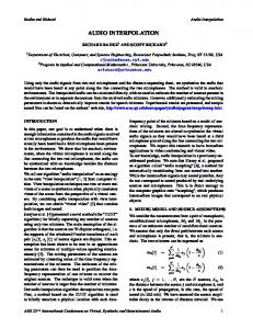
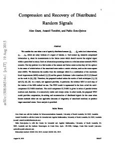
Level-3 (40 blocks) Level-2 (63 blocks) Level-1 (191 blocks)
Level-0 (797 blocks)
(a) Hierarchical segmentation update
(c) Original frame
(d) Frame predicted using MQD-DAS
(b) Disparity map refinement using MQD-DAS
(e) Disparity map using FBS-DE
(f) Prediction residuals using MQD-DAS
(PSNR = 27.55 dB, bpp = 0.068)
Figure 1. Results of MQD-DAS for a frame from the booksale sequence. The disparity map obtained using MQD-DAS has fewer spurious matches than the disparity map obtained using FBS-DE. (MQD-DAS bit count = 60% of FBS-DE bit count)
The MQD-DAS algorithm is illustrated in Fig.1. This algorithm was tested on several typical stereo pairs, including frame pairs from stereoscopic sequences, and the bits-per-pixel (bpp) needed to represent the disparity map and the segmentation overhead was compared with the bpp needed to represent the disparity map obtained using FBS-DE at similar PSNR values. The comparison is tabulated in Table 1, where it can be seen that a saving in bpp ranging from 25-55% can be obtained by using MQD-DAS. More important, but perhaps not entirely obvious from this brief summary, with this approach the bpp required becomes approximately proportional to the local disparity detail. Table 1: bpp comparison between FBS-DE and MQD-DAS at similar PSNRs after compensation
Image pair ->
Booksale
Crowd
Aqua
Piano
Train
Tunnel
Fl. Grdn
Lake
G.photo
FBS-DE
0.112
0.117
0.120
0.110
0.116
0.119
0.088
0.120
0.112
MQD-DAS
0.067
0.071
0.079
0.060
0.085
0.050
0.055
0.053
0.050
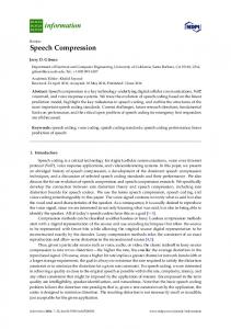
3.3.2 Stereoscopic sequence coding Compared to still picture encoding, sequence encoding schemes achieve additional compression of an order of magnitude by exploiting the temporal redundancy between frames. Low bit-rate coding of the auxiliary sequences implies achieving further compression on top of this. As mentioned before, the main sequence is independently coded at a relatively high quality. The MPEG-recommended frame structure of I, P, and B frames provides random access, editability and independent decodability of video segments. To extend these features to encoding a multi-view sequence, we retain a similar frame structure across all views. The auxiliary views can be coded in several ways. The optimal encoder should remove both intra-view and inter-view redundancies. We denote the I, P, B pictures of the main view using IM, PM, and BM. The corresponding pictures in the auxiliary view are represented by IA, PA, and BA. Considering such dependent coding while retaining the described frame structure, we notice: 1. An IA-frame can be coded using disparity estimation w.r.t the corresponding I M-frame. Since I-frames typically constitute a considerable fraction of the overall bit count, the reduction of this bit count in the auxiliary views significantly reduces the net bit count compared to independent coding. By applying MQD-DAS instead of FBS-DE the bit count can be further reduced. 2. A PA-frame can be predicted bidirectionally from the previous intra-view reference frame and the corresponding P M-frame. Thus temporal occlusions as well as perspective-based occlusions can be handled effectively. This can result in considerable reduction in residual coding overhead. 3. Similarly, a BA-frame can be predicted tri-directionally, from the past and future intra-view references and the corresponding B M-frame. Since BA frames would in our scenario not be used in the prediction of any other frame, the residual coding for these frames could be varied depending on the application requirements.
Thus PA and BA frames use a combination of disparity compensated prediction (DCP) and motion compensated prediction (MCP), as illustrated in Fig.2. The choice between MCP and DCP at the block level is influenced by several factors such as, (1) quality of the intra-view and inter-view reference frames (since auxiliary views are coded at a lower rate, the intra-view
main stream
MCP
IM
MCP PA
DCP
BA
MCP
BM
DCP
IA DCP
auxiliary stream
MCP
MCP
PM
Figure 2. Disparity and Motion Compensated Prediction modes in a two-view sequence.
PA DCP
MCP
PM
references are typically of poorer quality than the inter-view reference frame that belongs to the main sequence), (2) extent of frame-to-frame motion, (3) extent of view-to-view disparity, (4) match between left and right cameras, (5) disparity being a scalar for orthoscopic stereo, and (6) the need for synthesizing intermediate views at the decoder (since, if MCP is chosen, no disparity map is available at the decoder). Since the last factor requires DCP for all blocks, we consider two configurations of coders, configuration-1in which DCP is used for all blocks and configuration-2 in which a complete disparity map for each frame is not available at the decoder. The performance of the configuration-1 coder is improved by using MCP on top of DCP for undercompensated blocks. The MQDDAS algorithm is extended to include motion estimation by splitting a block only if sub-block motion estimates as well as subblock disparity estimates differ, which we refer to as MQD-DMAS. Such a configuration requires segmenting each auxiliary view frame. This does not scale well with multiple views. Since segmentation requires both computational and coding overheads, it would be better if either or both can be reduced. This can be achieved by sharing the segmentation among several frames. However this would require sacrificing the paradigm of finding the best match for the block to be estimated in the reference frame and instead follow the paradigm of ‘tracking’ the segment in the reference frame to the frame being estimated. Such tracking would result in multiple estimates for some regions and no estimates for some others (refer to 12 for a discussion on this). Hence, techniques for resolving among multiple matches and techniques for filling in regions with no estimates are needed. One such technique, referred to as reversed-DBS in configuration-1 (RDBS-1), wherein the main view frames are segmented based on disparity and the auxiliary view is predicted by reversing the direction of prediction, was described by us in 12 along with a suitable technique to handle regions with multiple and no matches. Going one step further, the number of segmentations can be further reduced by tracking the segments in the temporal domain also; thus the segmentation overhead can be shared by several multi-view frames. The main view can also be coded based on segment tracking. However no elegant method exists for resolving multiple matches and filling-in prediction-less regions. Hence, in spite of being computationally attractive, this technique (referred to as segment tracking configuration-1 or ST-1) would result in objectionable artifacts in the absence of considerable residual coding. In the ‘forward matching’ as well as the ‘tracking’ schemes above, mixed resolution coding can be achieved in a straightforward fashion by performing the MQD-DMAS for the auxiliary view frames only up to the desired resolution level on the pyramid and encoding the residuals at that level. The decoder in this case should have the capability to interpolate the lower resolution frame up to the main view resolution. These sequence coding extensions were tested on a few locally generated stereoscopic sequences, and on the DISTIMA 13 standard sequences. The rate-distortion* (bpp vs. PSNR) performance of these methods was compared against the performance of their FBS-based counterparts in each of the configurations. MQD-DMAS consistently outperforms FBS based compensation, except in the case of ST-1. Configuration-2 is always better than configuration-1, in terms of R-D performance. However configuration-1 would be needed if view interpolation were needed at the decoder. MQD-DMAS offers a significant increase in PSNR (0.7 - 2.5 dB) over FBS estimation at low excess bandwidths, which is, of course, our primary objective. By sacrificing resolution via mixed resolution coding, the quality can be further boosted for a given excess bandwidth by using better residual coding to suppress objectionable artifacts. Refer to 11 for details of the experiments. The ‘forward matching’ methods can be extended to multi-view coding in a straightforward fashion. The main view will be the central view. Since the correlation with the main view decreases as the auxiliary view gets farther away from it, the predictions can be augmented by predicting these views w.r.t to the corresponding frames in the main view and another auxiliary view that has already been coded. RDBS can be extended to multiple views by making the disparity estimation more robust by employing multi-baseline disparity estimation, as discussed in 15. MQD-DAS improves the quality of the disparity map by providing a smooth estimate over entire objects while preserving disparity discontinuities at the same time. These improved disparity maps can be used to better synthesize intermediate views between the available views to provide a continuum of views to an observer.
* Distortion in image coding contexts means image intensity errors introduced by the coding-decoding process, in contrast to the image geometry or content perception errors introduced by perspective, lens aberrations, etc.
4. SPECIFICALLY MULTI-VIEW ISSUES This section summarizes our work on specifically multi-view sequence coding issues; it is derived in large part from the Ph.D. thesis of Jeffrey S. McVeigh 16. 4.1. Context This work was performed within the context of attempting to solve two separate, yet interrelated, problems: (1) how to select the optimal reference frame for the predictive, interframe coding of multi-view video, and (2) how to accurately interpolate intermediate views from two decoded images given only a block-based disparity map and the relative location of the desired view between the given views. We first highlight a few key observations regarding disparity and occlusion, which will prove useful in our solution to these problems. 4.2. Observations on disparity and occlusion Our first observation is that, since disparity is defined as the vector distance between the locations of corresponding patches in two appropriately aligned image views, the disparity vector of a patch in one view is equal to the negated disparity vector of the corresponding patch in the other image. This fact implies that if we are given a unidirectional disparity map, the completely reversed map is also known. This relationship may be used to flag as questionable bidirectional disparity estimates that are inconsistent with this observation. Our second observation, a corollary to the one-to-one correspondence of bidirectional disparity maps, is that a discontinuity in a disparity map along an epipolar* line indicates an occlusion, equal in extent to the extent of the discontinuity. This follows from the geometry of occlusions, where one scene object partially obscures another object at a greater depth. This observation will prove quite useful for the detection of occluded regions, and for the refinement of erroneous disparity estimates. Our third observation is that the reliability of a disparity estimate for a contiguous region of pixels can be easily approximated by the prediction signal-to-noise ratio of the image region, where the noise is defined as the distortion between the original region and the corresponding region in the reference image. This measure is empirically a more robust confidence measure than distortion per se, probably due to the difficulty of disparity estimation when the regions being matched have relatively small intensity variations. 4.3. Optimal reference frame selection The goal of the prediction stage of any interframe video compression scheme is to minimize both the distortion between the predicted and original frames, and the bit count needed to describe the prediction. Since an accurate prediction is only possible if the image region is visible in the reference frame, the most basic factor affecting predictive coding performance is the extent of occlusion in the original frame with respect to the reference frame. It is, therefore, imperative that the minimum occlusion frame be chosen as the reference for the predictive coding of multiple frames related by time or perspective. In monoscopic, or single-view, video, the reference frame with the minimum occlusion is typically the temporally closest frame. Indeed, this relationship is utilized in the MPEG and H.26x classes of video compression standards, where the temporally closest previous and/or future decoded frames are used in the prediction phase. The problem becomes considerably more difficult, and interesting, when we expand the dimensionality of the problem to include two, or more, views of the scene. The basic structure of our approach is as follows 17: (1) establish a sampling grid that relates each frame in the multi-view sequence to another frame, (2) perform disparity estimation once for the frame to be compressed using the reference frame indicated by the sampling grid, (3) process the resulting disparity map via field reversal (Observation 1) and signal-to-noise ratio thresholding (Observation 3) to eliminate erroneous estimates, (4) generate composite disparity maps for each candidate reference frame through simple vector addition of the processed maps, and (5) calculate the variance of the composite maps, and select the reference frame with the minimum disparity variance. This selection criteria is based on Observation 2, which indicates that the frame with lowest disparity variance is the minimum occlusion frame, and hence, should yield the best prediction. We have performed this method of reference frame selection on numerous stereoscopic and multi-view videos. Compared to fixed, pre-selected reference frame schemes, this adaptive selection method yields 10-30% reductions in overall bit rates. This approach also achieved rate-distortion performance within 1% of an exhaustive search method, where the reference frame was selected by performing a complete disparity estimation for each candidate frame, and it required only about 1/4 the processor cycles. The major cost of this technique is that it requires more than twice the storage of either a fixed or exhaustive search * An epipolar line is a line of intersection of either camera’s image plane with the plane that contains an object point, the corresponding image point, and the center of projection of the “other” camera’s lens.
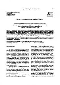
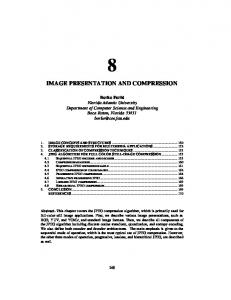
method, due to its need to retain multiple disparity maps. One final note on reference frame selection: as discussed in section 2.2., disparity estimation is in a sense simpler than motioncompensated prediction. However, when we look quantitatively at the six decision issues enumerated in section 3.3.2, we see that, for practical temporal intervals between frames of various types, and for practical spatial intervals between perspective views, the optimal reference frame may be either the temporally closest intra-view frame or a contemporaneous frame from an adjacent perspective. Although the epipolar line constraint restricts disparity estimation to a one-dimensional search, only a single depth plane will exhibit zero disparity for two perspective views, while the majority of pixels undergo no motion displacement between two temporal frame samples. This should be fairly obvious, since motion sequences are of necessity spaced in time so that the frame-to-frame differences are imperceptible, whereas, in contrast, stereopsis is stimulated only when the difference between adjacent views can be perceived. Thus, as a practical matter, the combination of motion and disparity compensation gives the best prediction. 4.4. Interpolation from a noisy disparity map Given the actual disparity map relating two perspective views, interpolating the unoccluded portions is a relatively simple, geometric procedure of calculating the intersection of each pixel's disparity vector with the intermediate view's image plane, and mapping the corresponding pixel's intensity value, from either given view, to the new frame. However, in the real-world we must overcome the difficulties that the disparity map is unknown and must be estimated, and that occluded pixels, by definition, do not have a disparity value. Previously reported interpolation schemes have attempted to generate a very accurate and dense disparity map via optical flow analysis, and they have either completely neglected the effect of occlusions or have made assumptions regarding occlusions that are invalid for perspective interpolation 18,19,20. Since we wish to perform interpolation within the context of a complete multi-view video compression system, we must rely on the noisy, block-based disparity map used to encode one view from another, and we must utilize valid assumptions to accurately infer disparity information for the relatively large occluded regions found in real-world perspective views. We accomplish this task by returning to our observations on disparity and occlusion, and following these steps: (1) eliminate erroneous estimates from the initial disparity map via field reversal (Observation 1) and SNR thresholding (Observation 3), (2) adjust the location of disparity discontinuities/occlusions (Observation 2) by examining the prediction performance of the disparity map on the given extreme views (we refer to this operation as “self-synthesis”), (3) infer disparity values for detected occlusions from neighboring, unoccluded pixels, and (4) map pixel intensity values to the intermediate view using the complete, processed disparity map. We note that the initial (block-based) disparity map acts as a guide as to how the map may be perturbed by the self-synthesis operation, which yields pixel-accurate unoccluded region boundaries and occlusions with minimal computational complexity and no transmission overhead in relation to the efficiently encoded block-based map. We illustrate the results of our interpolation method by the example in Fig.3. Since the scene objects are static and the camera motion consists of a relatively uniform translation in the horizontal direction, we used two frames, offset by three frame periods, from the standard Flower Garden sequence as a binocular image pair. Frame 3 was predicted and encoded from Frame 0 using a fixed-sized, block-based disparity estimation and compensation routine. The resulting disparity map initially was processed via field reversal and SNR thresholding to eliminate probably false estimates (Fig.3c). The self-synthesis procedure was then applied to further refine the location of displacement discontinuities. The majority of spurious disparity estimates after this stage are contained within feature-less regions of the image (e.g., the sky). Finally, Frame 1 was interpolated using the processed map and by inferring disparity for occluded regions (Fig.3f). This approach yields an interpolated frame that is subjectively superior to a basic interpolator that directly uses the initial, unprocessed disparity map; quantitatively, the PSNR for this frame surpassed that of the basic interpolator by 3.6 dB.
5. CONCLUSION In the 3D-stereoscopic and multi-view video scenario where compatibility demands at least one conventionally coded stream, we have demonstrated a unified framework for disparity and motion compensation based compression and interpolation. We have quantitatively demonstrated and compared the performance of several generations of increasingly sophisticated algorithms within this framework, and we have described a decision algorithm for optimal selection of reference frames. We have demonstrated a method for subjectively-pleasing viewpoint interpolation that fits within this framework and overcomes the real-world problems of disparity estimation errors and occlusions.
a. Original frame 0
c. Initial block-based disparity map
e. Original frame 1
b. Original frame 1
d. Refined disparity map
f. Interpolated frame 1
Figure 3. Interpolation results for Flower Garden sequence. A fixed-size, block-based disparity map was generated to predict frame 3 from frame 0. The map was then processed using field reversal and the self-synthesis operation to yield the refined disparity map in (d). The black regions indicate likely occlusions, and the gray-scale values for the remaining, unoccluded pixels represent the disparity magnitude. Frame 1 was then interpolated using the refined disparity map and by inferring disparity for occluded regions, which yielded a PSNR of 28.14 dB.
ACKNOWLEDGMENTS This work was supported in part by [D]ARPA Grant No. MDA 972-92-J-1010.
REFERENCES 1. T. S. Huang, “Bandwidth Compression of Optical Images”, Ch I (pp 1-42) in Progress in Optics, vol. X, E. Wolf (ed.), North-Holland/American Elsevier, 1972. 2. M. Rabbani and P. W. Jones, Digital Image Compression Techniques, SPIE Optical Engineering Press, Tutorial Texts in Optical Engineering Vol. TT7, SPIE, Bellingham WA, 1991. 3. D. A. Huffman, “A Method for the Construction of Minimum-Redundancy Codes”, in Proceedings of the Institute of Radio Engineers, vol. 40, pp. 1098-1101, 1952. 4. H. Tilton, “Broadcast Standards for 3D HDTV”, in Proceedings of the International Symposium on Three Dimensional Image Technology and the Arts, Tokyo, February 1992, pp 187-191. 5. V. S. Grinberg, G. W. Podnar, and M. W. Siegel, “Geometry of Binocular Displays”, in Proceedings of the SPIE Conf. of Stereoscopic Displays and Virtual Reality Systems, April 1994 (publication), vol. 2177, pp. 56-65. 6. I. Dinstein, G. Guy, J. Rabany, J. Tzelgov, and A. Henik, “On Stereo Image Coding”, in Proceedings of the International Conference on Pattern Recognition, pp 357-359, IEEE, 1988. 7. H. Isono, Ch 6, pp 156-8, in Fundamentals of 3D Image Technology, T. Izumi (ed), Omshaw Publishing, 1995. 8. T. Fujii and H. Harashima, “Coding of an autostereoscopic 3D image sequence”, in Proceedings of the SPIE Vol. 2308, p. 930-941, Visual Communications and Image Processing'94, (published) September 1994 9. S. Panis, M. Ziegler, J.P. Cosmas: “Object-Oriented Monoscopic/Stereoscopic Image Coder”, in the 27th International Conference on Digital Signal Processing, Remissly, Cyprus, June 26-28, 1995. 10. D. Tzovaras, N. Grammalidis, and M. G. Strintzis, “Joint three-dimensional Motion/Disparity Segmentation for ObjectBased Image Sequence Coding”, in Optical Engineering, special issue on Visual Communications and Image Processing, vol. 35, pp. 137-145, January 1996. 11. Sriram Sethuraman, “Stereoscopic image sequence compression using multiresolution and quadtree decomposition based disparity- and motion- adaptive segmentation”, Ph.D Thesis, Dept. of Electrical and Computer Engineering, Carnegie Mellon University, Pittsburgh PA, July 1996. 12. Sriram Sethuraman, M. W. Siegel, Angel G. Jordan, “Segmentation based coding of streoscopic image sequences”, in Proceedings of the IS&T/SPIE’s Symposium. on EI (San Jose), 1996, vol. 2688, pp 420-9. 13. DISTIMA stereoscopic test sequences, generated and distributed by CCETT, France under the RACE-DISTIMA European project, October 1994. 14. Sriram Sethuraman, M. W. Siegel, Angel G. Jordan, “A multiresolutional region based segmentation scheme for stereoscopic image compression”, in Proceedings of the IS&T/SPIE’s Symposium. on EI (San Jose), 1995, vol. 2419, pp. 265-75. 15. M. Okutomi and T. Kanade, “A multiple-baseline stereo”, Technical Report CMU-CS-90-189, November 1990. 16. J. S. McVeigh, Efficient Compression of Arbitrary Multi-view Video Signals, Ph.D. Dissertation, Department of Electrical and Computer Engineering, Carnegie Mellon University, Pittsburgh PA, June 1996. 17. J. S. McVeigh, M. W. Siegel and A. G. Jordan, “Adaptive Reference Frame Selection for Generalized Video Signal Coding”, in Proceedings of the IS&T/SPIE’s Symposium. on EI (San Jose), 1996-January, vol. 2688, pp 441-9. 18. C. Cafforio, F. Rocca and S. Tubaro, “Motion compensated image interpolation”, in IEEE Transactions on Communications, vol. 38, No. 2, pp 215-222, February 1990. 19. J. Ribas-Corbera and J. Sklansky, “Interframe interpolation of cinematic sequences”, in J. Visual Communication and Image Representation, vol. 4, No. 4, pp. 392-406, December 1993. 20. R. Thoma and M. Bierling, “Motion compensating interpolation considering covered and uncovered background”, in Signal Processing: Image Communication, vol. 1, No. 2, pp. 191-212, October 1989.