Nordic Acoustical Meeting Helsinki, 12 – 14 June 1996
E7
IMPLEMENTATION OF A VIRTUAL AUDIO REALITY SYSTEM Jyri Huopaniemi 1, Lauri Savioja 2, Tommi Huotilainen 1,3, and Tapio Takala 2 1
Helsinki University of Technology Laboratory of Acoustics and Audio Signal Processing Otakaari 5 A, FIN-02150 Espoo, Finland
[email protected] 2 Helsinki University of Technology Department of Computer Science Otakaari 1, FIN-02150 Espoo, Finland
[email protected],
[email protected] 3 ABB Industry Oy, Pulp & Paper P.O.Box 94, FIN-00381 Helsinki, Finland
[email protected]
1
INTRODUCTION
Virtual audio reality environments have in recent years become popular in such fields as computer music, acoustics, multimedia, and telecommunications [1]. There are often computational constraints that lead to very simplified systems that faintly resemble the physical reality. We present a distributed expandable virtual audio reality system that can accurately yet efficiently model room acoustics and spatial hearing in real time. In Chapter 2, real-time binaural modeling of room acoustics is discussed. Digital signal processing (DSP) aspects of room acoustics and head-related transfer function (HRTF) implementation are overviewed in Chapter 3. In Chapter 4, the implementation of the system is described. There are companion papers that discuss parts of the Helsinki University of Technology virtual audio reality project in greater detail [2] [3]. A more complete description of the DIVA (Digital VIrtual Acoustics) system is given in [4] 2
REAL-TIME BINAURAL ROOM ACOUSTICS MODELING
Computers have been used nearly thirty years to model room acoustics. A good overview of current modeling algorithms is presented in [5]. Performance issues play an important role in the making of a real-time application [6] and therefore there are quite few alternative algorithms available. Methods that try to solve the wave equation are far too slow for real-time purposes. Ray tracing and image source methods are the most often used algorithms which base on the geometrical room acoustics. Of these, the image source method is faster for modeling low-order reflections.
331
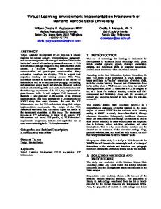
Figure 1.
The Sigyn Hall in Turku, Finland, is one of the halls where simulations were carried out [7].
For auralization purposes simulations must be done binaurally. Some binaural simulation methods are presented in articles [8], [9]. The image source method is good for binaural processing, since the incoming directions of sounds are the same as the orientations of the image sources. An example of a geometrical concert hall model is illustrated in Fig. 1. 2.1
The Image Source Method
The image source method is a geometrical acoustics based method and is widely used to model room acoustics. The method is thoroughly explained in many articles [10], [11]. The algorithm implemented in this software is quite traditional. There are although some enhancements to achieve a better performance level. In the image source method the amount of image sources grows exponentially with the order of reflections. Therefore it is necessary to calculate only the image sources that might come visible during the first reflections. To achieve this we make a preprocessing run with ray tracing to check visibilities of all surface pairs. 2.2
Real-Time Communication
In our application the real-time image source calculation module communicates with two other processes. It gets input from the graphical user interface. This input represents the movements of the listener. The model generates output for the auralization unit. To calculate the image sources the model needs following input information: 1) the geometry of the room, 2) the materials of the room, 3) the location of the sound source, and 4) the location and orientation of the listener. The model calculates positions and orientations of image sources. A following set of parameters concerning each image source is passed to sound processor: 1) the distance from the listener, 2) the azimuth angle to the listener, 3) the elevation angle to the listener, and 4) two filter coefficients which describe the material properties in reflections.
332
The amount of image sources depends on the available computing capacity. In our realtime solution typically 20-30 image sources are passed forward. The model keeps track of the previously calculated situation. Newly arrived input is checked against that. If changes in any variable are large enough, some updating process is necessary. 2.3
Updating the Image Sources
The main principle in the updating process is that the system must respond immediately to any changes in the environment. That is reached by gradually refining calculation. In the first place only the direct sound is calculated and its parameters are passed to the auralization process. If there are no other changes queuing to be processed first order reflections are calculated, and then second order, and so on. In a changing environment there are three different possibilities that may cause recalculations: 1) movement of the sound source, 2) movement of the listener, and 3) turning of the listener. If the sound source moves, all image sources must be recalculated. The same applies also to the situation when something in the environment, such as a wall, moves. The visibilities of all image sources must be validated whenever the listener moves. The locations of the image sources do not vary and therefore there is no need for recalculation. If the listener turns without moving there are no changes in the positions of the image sources. Only the azimuth and elevation angles may change and those must be recalculated. 2.4
Material Parameters
Each surface of the modeled room has been given sound absorption characteristics, generally in octave bands from 125 Hz to 4000 Hz. In a real-time implementation, these frequency-dependent absorption characteristics are taken into account by designing first-order IIR approximations to fit the magnitude response data of each reflection coefficient combination. 3
AURALIZATION ISSUES
The goal in real-time auralization is to preserve the acoustical characteristics of the modeled space to such extent that the computational requirements are still met. This places constraints to the accuracy and quality of the final auditory illusion. The steps required in our auralization strategy can be divided in the following way: 1) model the first room reflections with an image-source model of the concert hall, 2) use accurate HRTF processing for the direct sound, 3) apply simplified directional filtering for the first reflections, and 4) create a recursive reverberation filter to model late reverberation. 3.1
Real-Time Room Impulse Response Processing
The use of methods based on geometrical room acoustics in real-time modeling of the full room impulse response is out of the calculation capacity of modern computers. To solve this problem, hybrid systems that exhibit the same behavior as room impulse responses in a computationally efficient manner have to be found. 333
We ended up using a recursive digital filter structure based on earlier reverberator designs [12], [13], which is computationally realizable yet gains good results [14]. The structure combines the implemented image-source method and late reverberation generation. The early reverberation filter is a tapped delay line with lowpass filtered outputs designed to fit the early reflection data of a real concert hall. The recursive late reverberation filter structure is based on comb and allpass filters. 3.2
HRTF Filter Design
Sound source localization is achieved in a static case primarily with three cues [15]: 1) the interaural time difference (ITD), 2) the interaural amplitude difference (IAD), and 3) the frequency-dependent filtering due to the pinnae, the head, and the torso of the listener. The head-related transfer function (HRTF) represents a free-field transfer function from a fixed point in a space to a point in the test person's ear canal. There are often computational constraints that lead to the need of HRTF impulse response approximation. This can be carried out using conventional digital filter design techniques. In most cases, the measured HRTFs have to be preprocessed in order to account for the effects of the loudspeaker, microphone, (and headphones for binaural reproduction) that were used in the measurement. Further equalization may be applied in order to obtain a generalized set of filters. Such equalization methods are free-field equalization and diffuse-field equalization. Smoothing of the responses may also be applied before the filter design. 3.2.1
Minimum-phase Reconstruction
An attractive solution for HRTF modeling is to reconstruct data-reduced minimumphase versions of the modeled HRTF impulse responses. A mixed-phase impulse response can be turned into minimum-phase form without affecting the amplitude response. The attractions of minimum-phase systems in binaural simulation are: 1) the filter lengths are the shortest possible for a specific amplitude response, 2) the filter implementation structure is simple, 3) minimum-phase filters perform better in dynamic interpolation. According to Kistler and Wightman [16], minimum-phase reconstruction does not have any perceptual consequences. With minimum-phase reconstructed HRTFs, it is possible to separate and estimate the ITD of the filter pair, and insert the delay as a separate delay line to one of the filters in the simulation stage. The delay error due to rounding of the ITD to the nearest unit-delay multiple can be avoided using fractional delay filtering (see [17] for a comprehensive review on this subject). 3.2.2
FIR and IIR Filter Implementations
Digital filter approximations (FIR and IIR) of HRTFs have been studied to some extent in the literature over the past decade. Filter design using auditory criteria (which is desired because we are interested in audible results) have been proposed by quite few authors, however. There are two alternatives to a non-linear frequency scale approach: 1) weighting of the error criteria, and 2) frequency warping. HRTF filter design aspects are studied in a companion paper [2].
334
3.3
Real-Time Auralization
The auralization system obtains the following input parameters which are fed into the computation: • direct sound and image-source parameters • HRTF data for the direct sound and directional filters (minimum-phase WFIR or WIIR implementation stored at 10° azimuth and elevation intervals) • “dry” audio input from a physical model or an external audio source The output of the auralization unit is at present directed to headphone listening (diffuse-field equalized headphone, e.g., AKG K240DF), but software for conversion to transaural or multispeaker format has also been implemented. 4
SYSTEM IMPLEMENTATION
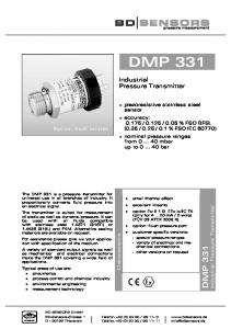
We have used a distributed implementation on an Ethernet-based network to gain better computational power and flexibility. Currently we use one Silicon Graphics workstation for real-time visualization and the graphical user interface (GUI) and another for imagesource calculations. We have also used a Texas Instruments TMS320C40-based signal processor system that performs direction- and frequency-dependent filtering and ITD for each image source, the recursive reverberation filtering, and the HRTF processing. The basic idea for the Ethernet-based system is to use the multiprocessor system as a remote controlled signal processing system. In the transfer process, the audio source signal and/or control parameter block is transmitted through the network to the signal processing system, which receives the data, processes the audio signal and sends the stereophonic audio result back to the workstation in real time (Fig. 2). Silicon Graphics for GUI
Silicon Graphics for Image Source Computation
ATM / Ethernet
Optional Audio Source Input
Stereo Monitor Output
A/D
D/A
S/PDIF
TMS320C40 Card 1
TMS320C40 Card 2
TMS320C40 Card N
Apple Macintosh
Figure 2.
Block bus
...
Message bus
...
The distributed implementation over an Ethernet-based network. 335
TMS320C40-A DMA Ch3 Com Port 3
Com Port 4
DMA
Com Port 0 Apple Macintosh
Audio buffer Muisti
DMA Ch4
Audio Process
CPU
Block Bus
TMS320C40-B DMA Ch3 Com Port 3
DMA Parameter Muistibuffer Audio Process
Figure 3.
Com Port 4
Audio source input
Com Port 1
Stereo Audio Monitor Output
CPU
View of the interconnections in the multiprocessing environment. The DSPbased auralization system sound input is taken from an external audio interface.
There are three optional audio source inputs to the system. The simplest implementation is to use the previously overviewed system using a stereo A/Dconverter which is connected to the signal processor B (Fig. 3). We have also developed real-time algorithms of model-based sound synthesis and these are optional audio sources for the system. The synthesization of the audio source can be processed by the signal processor system or the workstation (via the network) [4]. 4.1.1
Real-Time DSP Audio Processing
In the current multiprocessor system using two TMS320C40s, processors A and B can be assigned different calculation routines according to the system requirements. The following discussion is for a situation, where the audio source is an external input that can be, e.g., a MIDI synthesizer (see Fig. 3). The host computer transfers the auralization parameters from Ethernet to the signal processor A which is programmed to transfer the parameter block directly to processor B using the DMA coprocessor which can automatically reinitialize its registers via linked lists stored in memory. This allows the DMA to transfer the parameters continuously without any intervention by the CPU (Fig. 3). The block is transferred through the block bus. Processor B receives the parameter block and the DMA coprocessor automatically transfers the block to the parameter buffer. The received auralization parameters control the auralization processing. Processor B performs audio I/O routines, calculates direction- and frequency-dependent attenuation and ITD for each image source, and carries out the HRTF and directional filtering for headphone or loudspeaker listening. The intermediate
336
processed audio result is sent to processor A through the block bus. In the next phase, the DMA coprocessor of processor A moves the audio signal to a buffer. Buffering is intended to compensate for the internal interrupt delay of the Macintosh system, which causes fluctuation of processing speed. Processor A performs the stereophonic recursive reverberation calculation and the audio result is sent to the host which transmits the samples immediately to the Ethernet as a part of an audio block. 4.1.2
Signal Processing Benchmarks
The Texas Instruments’ TMS320C40 processors we are using operate at 40 MHz, and thus at 32 kHz sampling rate the theoretical amount of floating-point operations per sample interval is 625. If the audio I/O and some additional multiprocessing routines are subtracted, the multiprocessing system is capable of 1210 operations per sample interval at 32 kHz sampling rate. In a real-time application, a one-processor implementation enables accurate HRTF processing for the direct sound with 30-50 tap FIR filters, ITD, and direction- and frequency-dependent filtering for 20-30 image sources and simplified reverberation. If both of the processors are used, the full recursive reverberation routine can be utilized, and the amount of image sources can be greater. An additional model based sound synthesis routine will require a significant amount of calculation, depending on the instrument. 5
SUMMARY
We have developed a soft- and hardware system for producing virtual audiovisual performances in real-time. The listener can freely move in the virtual concert hall where a virtual musician plays a virtual instrument. Early reflections in the concert hall are computed binaurally with the image-source method. For late reverberation we use a recursive filter structure consisting of comb and allpass filters. Auralization is done by using the interaural time difference (ITD) and head-related transfer functions (HRTF). 6
REFERENCES
1.
Begault, D. 3-D sound for virtual reality and multimedia. AP, 1994.
2.
Huopaniemi, J., and Karjalainen, M. 1996. HRTF filter design based on auditory criteria. Proc. Nordic Acoustical Meeting (NAM’96), Helsinki, 1996.
3.
Hänninen, R., and Välimäki, V. 1996. An improved digital waveguide model of a flute with fractional delay filters. Proc. Nordic Acoustical Meeting (NAM’96), Helsinki, 1996.
4.
Takala, T., Hänninen, R., Välimäki, V., Savioja, L., Huopaniemi, J., Huotilainen, T., Karjalainen, M. 1996. An integrated system for virtual audio reality. Presented at the 100th Audio Engineering Society (AES) Convention, preprint no. 4229 (M-4), Copenhagen, Denmark, May, 1996.
337
5.
Kuttruff, H. 1995. Sound field prediction in rooms. In. Proc. Int. Congr. on Acoustics (ICA’95), Trondheim, Norway, 1995, pp. 545-552.
6.
Kleiner, M., Dalenbäck, B.-I., and Svensson, P. 1993. Auralization – an overview. J. Audio Eng. Soc., vol. 41, no. 11, pp. 861–875.
7.
Lahti, T., and Möller, H. 1996. The Sigyn Hall, Turku - A concert hall of glass. Proc. Nordic Acoustical Meeting (NAM’96), Helsinki, 1996.
8.
Lehnert, H., and Blauert, J. 1992. Principles of Binaural Room Simulation. Applied Acoustics, vol. 36, no. 3-4, pp. 259-291.
9.
Martin, J., Van Maercke, D., and Vian, J.-P. 1993. Binaural simulation of concert halls: a new approach for the binaural reverberation process. J. Acoust. Soc. Am., vol. 94, no. 6, pp. 3255-3264.
10.
Allen, J., and Berkley, D. 1979. Image method for efficiently simulating small-room acoustics. J. Acoust. Soc. Am., vol. 65, no. 4, pp. 943–950.
11.
Borish, J. 1984. Extension of the image model to arbitrary polyhedra. J. Acoust. Soc. Am., vol. 75, no. 6, pp. 1827-1836.
12.
Schroeder, M. 1962. Natural sounding artificial reverberation. J. Acoust. Soc. Am., vol. 10, no. 3.
13.
Moorer, J. 1979. About this reverberation business. Computer Music J., vol. 3, no. 2, pp. 13–28.
14.
Huopaniemi, J., Karjalainen, M., Välimäki, V., and Huotilainen, T. 1994. Virtual instruments in virtual rooms - a real-time binaural room simulation environment for physical models of musical instruments. Proc. 1994 Int. Computer Music Conf., Århus, Denmark, 1994, pp. 455-462.
15.
Blauert, J. 1983. Spatial Hearing. M.I.T. Press, Cambridge, MA.
16.
Kistler, D., and Wightman, F. 1992. A model of head-related transfer functions based on principal components analysis and minimum-phase reconstruction. J. Acoust. Soc. Am., vol. 91, no. 3, pp. 1637–1647.
17.
Laakso, T. I., Välimäki, V., Karjalainen, M., and Laine, U. K. 1996. Splitting the unit delay - tools for fractional delay filter design. IEEE Signal Processing Magazine, vol. 13, no. 1, pp. 30-60.
18.
Smith, J. 1983, Techniques for digital filter design and system identification with application to the violin, Ph.D. dissertation, CCRMA, Department of Music, Stanford University (Standord, CA, 1983).
19.
Jot, J.-M., Larcher, V., and Warusfel, O. 1995. Digital signal processing issues in the context of binaural and transaural stereophony. Presented at the 98th AES Conv., preprint 3980 (E-2), Paris, France, 1995.
338