3D CMOS SOI for High Performance Computing Abou-Samra S. J.
Aisa P. A.
Guyot A. and Courtois B.
TIMA Laboratory
DEIS, University of Bologna
TIMA Laboratory
46 av. Félix Viallet
Viale Risorgimento 2
46 av. Félix Viallet
F-38031 Grenoble - France
I-40136 Bologna - Italy
F-38031 Grenoble - France
Tel.: (33) 4 76 57 48 12
Tel. : (39) 51 46 33 03
Tel.: (33) 4 76 57 46 15
[email protected]
[email protected]
[email protected]
ABSTRACT This paper addresses three topics : First, a new three-dimensional CMOS-SOI on SOI technology is presented, then design methodologies are proposed for this technology and last, a comparison is carried out between 2D and 3D designs. In this technology the P-channel devices are stacked over the N-channel ones. All gates are 100nm length. New design constraints are introduced. Consequently, new design methodologies have to be developed in order to fully take advantage of the outstanding features of 3D integration like for example the reduced length of interconnections. A 16x16 bit multiplier was designed in this technology. Comparative results between 2D and 3D integration are given here in terms of energy consumption, delay and area
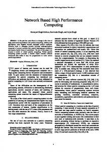
The geometries that are normally defined by lithography are now defined by the thickness of deposited films, thus allowing smaller and accurately reproducible gate lengths. Source
Gate Polysilicon
Drain Gate oxide
AlSiCu
AlSiCu
n+
n- p
n-
n+
Silicon
Oxide
Silicon
INTRODUCTION In this paper a new three dimensional 100nm channel length CMOS-SOI technology is presented. It consists of two layers of transistors - Silicon On Insulator on Silicon On Insulator [1]. This technology is being developed at the IMS (Institute for Microelectronics Stuttgart - Gremany). With three dimensional integration the density is increased, and thus, the interconnections are dramatically shortened. As the interconnection capacitances are predominant in deep submicron technologies [2, 7], substantial gains in energy consumption are obtained from 3D integration, but a new design methodology supported by new tools have to be developed. The paper is organised as follows : The technology is presented in the first part. The second part is devoted to the design methodologies, and the cell library is presented. In the third part multiplier designs (2D and 3D) are presented and compared from energy, delay and area points of view; finally some conclusions are drawn, and a brief perspective is given.
Fig. 1: A symmetrical T-Gate transistor. SDB/SIMOX-Wafers are used for the 3D-SOI technology. In the mesa structured active-silicon film, contact holes to the handle wafer are etched using a hardmask/spacer technique. The contact holes are filled with a polysilicon deposition and CMP-planarisation. After removing the hardmask, the symmetrical n-channel T-Gate transistors with 100nm channel length and a 6nm gate oxide are realised. An oxide for dielectric isolation is deposited and structured. In the next step a seed opening down to the n-channel transistor is produced and a selective lateral overgrowth epitaxy is done [1, 9]. During the growth process, the doping flow is switched from N -type to P-type. In the next step the overgrown silicon is planarised using CMP and the P-channel symmetrical T-Gate transistors are fabricated using the EDMOS technology. After a BPSG-oxide deposition the metallisation system is realised. Figure 2 shows a perspective view of the 3D structure.
TECHNOLOGY
lo
g2
pd iff
co nt
The 3D-SOI technology for low-power applications uses the symmetrical T-Gate transistor (Fig. 1). The T-Gate transistors are produced with the lithography-independent Edge-Defined MOS technology (EDMOS). The basic idea of this lithography independent nanometer silicon technology is the substitution of the lithography by suitable film deposition techniques [8].
iff nd log
poly2
lk Bu
via2 poly1
Fig. 2: 3D CMOS SOI.
Under operating conditions, the contact between the handle-wafer and the SIMOX silicon film supports the heat removal of the transistors. In addition, the handle wafer acts as a Vss supply connection.
outside the P-Type Silicon island. The common ground plane is actually not constraining. On the contrary, this saves the routing of the ground metal lines.
This technology introduces new design constraints. Some of them are addressed in the following section.
The design methodology developed must benefit from the features offered by this type of three dimensional integration. From the layout point of view, pass transistor logic seems to be suitable as, on one hand, less transistors are necessary per logical function, and on the other hand, the number of P-type transistors can be made smaller than the number of N-type ones leading to more relaxed layout constraints. But electrical simulations showed that pass transistor logic does not deliver the requiered performance (in terms of energy delay product), and that static CMOS is far better.
DESIGN METHODOLOGIES The first and most straightforward advantage of the stacking of the PMOS over the NMOS transistors is the substantial gain in density. This leads to reduced interconnections length. In deep submicron technologies, the capacitance introduced by the interconnections becomes predominant comparing to the intrinsic device capacitance [2, 7]. This remark becomes even more relevant for SOI technologies because intrinsic capacitances are smaller in SOI devices than in their bulk counterpart.
3D Interconnections This type of three dimensional integration introduces additionnal constraints on the design rules preventing a gain of a factor two in density. The inter-layer connectivity scheme is illustrated on figure 3. The structure is formed by two layers of Silicon with a layer of polisilicon in-between and another one on the top. Two metal layers are then available for local and global interconnects. The Silicon layers are connected together by a Silicon plug since the upper layer is grown epitaxially departing from the lower one which serves as a seed cristal. The first Silicon layer is also obtained by local epitaxy, and thus it can be easily grounded by using the bulk as a common ground plane. This save the area usually devoted to the routing of GND. There are two layers of polysilicon, one for each level of transistors. The poly-poly contact is a critical technological step; but from the design point of view, this contact is compulsory to achieve substantial gains in terms of density as far as static CMOS is concerned. Also, design methodologies are developed to take better advantage of this contact. As compared to 2D technology, the additionnal design rules constraints are due to the intermediate silicon level : indeed, one must be aware of making Metal1 to Poly1 or N-Type Si contacts
Design Styles
In the following, the adopted design style is static CMOS focusing on a particular family of logic functions : the self dual functions. The dual of a boolean function F is the function FD that is obtained by substituting the “and” and “or” operators in F. Self duality is achieved when F = F D . Lets take the example of the boolean function “majority of 3 variables” Maj (a, b, c) . MajD(a, b, c)
= (ab + ac + bc)D = (a + b)(a + c)(b + c)
= ... = (ab + ac + bc) = Maj(a, b, c) Once the self-duality of a function is established, as the N-type and P-type networks are identical, two topologies are then possible (Fig. 4). The chosen topology is of course the fastest one, i.e. the one with the less transistors in series (Fig. 4a). Now, from the three dimensional design point of view, figure 4a is very interesting. Indeed, as the N and P-type transistors networks are identical, they can be superimposed. The gates of the N-type transistors are connected using the poly-poly contact as in figure 3. The gain in density for this gate is 40%. The ideal gain of 50% cannot be reached as the total area in 3D is equal to the area of the P-type network in 2D, and the P-type transistors channels are wider than the N-type ones.
Fig. 3: 3D-SOI inter-layer connectivity.
length is the lithography independent 100nm channel (Fig. 1), leading to a high W/L ratio.
VDD a
a
b
b
c
c
a
a
b
b
c
c
Majority(a,b,c)
Fig. 4a : Self-dual majority
___ Fig. 5a : 3D Layout of Maj function
VDD a a
b
b
c c
a a
b c
b
c
Majority(a,b,c)
Fig. 4b : Alternative Self-dual majority
Tools and Standard-Cells A design kit for 3D integration has been developed under CADENCE DFW II. It includes DRC, ERC, LVS and automatic place and route of the standard cells. All electrical simulations are carried-out with HSPICE using BSIM3v3 models. The design tools had to be adapted to three dimensional design constraints. Standard cell library development has been carried out in parallel in both 2D SOI and 3D SOI. Our library contains only basic cells as the target was limited to a multiplier. These are not general purpose standard cell libraries. The gain in terms of area is here about 30%. It is not very high due to the fact that in the standard cell approach, the width of the cells is given by the number of I/O pins and thus is the same in 2D and 3D. The gain in density is of course higher in full custom designs
___ The Maj cell has been integrated in our basic cells library that we used to design the adder and multiplier. Actually, it is very frequently used for the reduction of the partial products. Figure 5 shows the two and three dimensional layouts. It can be noticed that the width is the same, and that in the 3D version (fig. 5a) there is no metal used for GND. In our libraries, all N-type transistors are designed with minimum width (except for buffers) and the widthes of the P-type ones are chosen so that the threshold of the gates is centered at half V DD. Using minimum width devices is acceptable here as the minimum
___ Fig. 5b : 2D Layout of Maj function
___ In table I, the 2D and 3D versions of the Maj (a, b, c) are compared from the density, total capacitance and delay points of view. The total capacitance is obtained by summing all the parasitic capacitance that are extracted; this includes the intrinsic capacitance and the interconnects. The intrinsic capacitance are the same for both 2D SOI and 3D SOI on SOI; meaning that the gain obtained comes only from the interconnections length reduction.
___ Table I: Results for Maj (a, b, c) 2D
3D
Gain (%)
Area (µm 2 )
588
352.8
40
Total capacitance (fF)
229.4
194.8
15
Delay (ps)
385
276
28.3
Table III : Monte-Carlo results
RESULTS AND COMPARISON In this section comparative results are presented for a 16x16 bit multiplier. This circuit was designed, extracted and electrically simulated in 2D and 3D.
16x16 Bit Multiplier The 16x16 bit multiplier is one of the benchmarks chosen to evaluate this technology. The energy dissipation in multipliers occurs mainly during the reduction of the partial products. A large part of the signal activity in the reduction tree is redundant (glitches). The rate of redundant activity highly depends on the reduction scheme. Table II shows the rate of useless energy dissipation for different sizes of Braun [3] multipliers. These results are based on logical simulation [10].
Architecture
Redundant transitions (%)
Braun [3]
54.6
Wallace-Dadda [6]
24.8
4-2 reductors
20.2
The multiplier has been designed in two and thee dimensions. The two and three dimensional layouts are shown in figures 7a and 7b.
Monte Carlo simulation [12] results for different 8x8 bit multiplier architectures are shown in table III. It is clear that balanced trees produce less hazards. Table II : Braun activity Number of bits
Redundant transitions (%)
2x2
0
4x4
13
8x8
40
16x16
65.9
The selected architecture for the 16x16 bit multiplier is based on a binary tree. It is composed of full adder (FA) with a reduction of 3:2 and carry save adder (CS) with a reduction of 4:2. For this latter adder, some carry bits are propagated horizontally (Fig. 6). For the final adder, the efficient Han and Carlson architecture [11] was chosen. It is based on the Brent and Kung carry propagation and generation cells [4].
1 2 3 4 5 6 7 8 0 0 0 1 1 1 2 2 FA FA CS CS CS CS FA CS
Figures 7a : 2D 16x16 bit Multiplier layout
9 10 11 12 13 14 15 16 15 14 13 12 11 10 9 8 7 6 5 4 3 2 1 2 2 3 3 3 4 4 3 3 2 2 2 2 2 2 1 1 1 0 0 0 0 0 CS CS CS CS CS CS CS CS CS CS CS CS CS CS CS CS CS CS CS FA FA HA CS CS CS CS CS CS CS CS CS CS CS CS CS CS CS CS FA FA CS CS CS CS CS CS CS FA FA CS CS FA
1 3 2 4 3 5 5 4 5 7 7 6 8 8 0 0 0 0 1 1 1 1 1 1 1 2 2 2 FA CS CS CS CS CS CS CS CS CS FA FA FA CS CS
8 8 7 7 8 8 2 2 2 2 2 1 CS CS CS CS CS CS CS CS CS CS CS CS
7 6 5 4 3 4 2 3 2 1 1 1 1 1 1 1 0 0 0 0 0 0 CS CS CS CS CS CS HAFA HA FA
1 3 3 2 5 3 3 2 4 4 4 4 4 4 4 4 4 4 4 4 3 4 3 2 2 2 2 0 0 0 1 0 0 0 1 1 1 1 1 1 1 1 1 1 1 1 1 1 0 0 0 0 0 0 FA FA FA CS FA FA FA CS CS CS CS CS CS CS CS CS CS CS CS CS CS FA
2 1 1 1 0 0 0 0
2 2 2 2
2 1 1 1
2 2 2 2 2
2 2 2 2 2 2
2 2 2 2 2 2
2 1 2 2 2 2
Figure 6: Binary tree with a 4:2 reduction ratio
# of bits to reduce # of bits of carry
# of bits to reduce # of bits of carry
# of bits to reduce # of bits of carry
ACKNOWLEDGEMENT This work is supported by the European Community ESPRIT IV project HIPERLOGIC (# 20023)
REFERENCES [1] S.J. Abou-Samra, V. Dudek, F. Ayache, A. Guyot, B. Courtois and B. Höfflinger, “Designing With 3D SOI CMOS” , In proc. of the 8 th International Symposium on SOI Technology and Devices (ECS'97), Paris, France, September 1997, pp. 384388. [2] J. Borel, “LP/LV Circuits : State of the Art and Prospects”, Low Power, Low Voltage Integrated Circuits: Technology and Design, Microelectronics Engineering, An International Journal of Semiconductor Manufacturing Technology, Vol. 39, Elsevier, Dec. 1997, pp. 1-6 [3] E. L. Braun, “Digital Computer Design”, New-York Academic, 1963
Figures 7b : 3D 16x16 bit Multiplier layout The results are summerised in table IV. As the CAD tool cannot easily handle 3D designs, the automatic place and route is far from optimal, leading to a relatively small gain in density. We are expecting to overcome these problems in the near future. concerning the total capacitance, a comparison between tables I and IV shows that the gain is much higher for the whole multiplier than for a single cell. This is because in the case of a single cell, the intrinsic device capacitance plays a major role, where in the macro design, the routing capacitance is predominant. The power-delay and energy-delay products are significantly improved by 3D integration. Table IV: Multiplier Results 2D
3D
Gain (%)
Area (mm 2)
4.21
3.67
12.8
Total capacitance (pF)
262.7
188.0
28.4
Delay (ns)
12.3
9.6
21.9
Energy/Operation (pJ)
556
387
30.4
Energy x Delay (pJ/MHz)
6.8
3.7
45.6
CONCLUSION A three dimensional CMOS SOI on SOI technology is presented and suitable design methodologies are proposed. The impact of 3D design is on circuit performance is measured through the comparison of layout simulation results of the same cuircuits designed in the palnar and the stacked versions of the same SOI devices. These results show that significant improvements are achieved (more than 45% for the Energy-Delay product). Larger improvements in circuit density are expected from full custom designs. Future work will focus on complex cells based designs and automated layouts in 3D.
[4] R. P. Brent, H. T. Kung, “A Regular Layout for Parallel Adders”, IEEE Transactions on Computers, Vol. C31, pp 261 - 264, March 1982. [5] A. P. Chandrakasan, R. W. Brodersen, “Low Power Digital CMOS Design”, Kluwer Academic Publishers, 1995 [6] L. Dadda, “Some Schemes for Parallel Multipliers”, Alta Frequenza, Vol. 34, March 1965, reprinted in E. E. Swartzlander, Vol. 1, IEEE Computer Society Press Tutorial, Los Alamitos, CA, 1990, pp. 349-356 [7] M. Dax, “Inspection, Measurment and Test”, Semiconductor International, March 1997, p. 64. [8] V. Dudek, W. Appel, L. Beer, G.Digele, B. Höfflinger, “Lithography-Independent Nanometer Silicon MOSFET’s on Insulator” , IEEE Transactions on Electron Devices ED 43(10), 1996, pp.1626-1632 [9] V. Dudek, W. Appel, L.Beer, B. Höfflinger, “A SOI 0.1um Epitaxial Channel MOSFET”, In proc. of the ESSDERC´95, The Hague, Edts. H.C. de Graaff, H. van Kranenburg, Editions Frontiers, 1995, pp. 221-224. [10] A. Guyot, S.J. Abou-Samra, “Modelling Power Consumption in Arithmetic Operators”, Low Power, Low Voltage Integrated Circuits: Technology and Design, Microelectronics Engineering, An International Journal of Semiconductor Manufacturing Technology, Vol. 39, Elsevier, Dec. 1997, pp. 245-255 [11] T. Han, D. A. Carlson, “Fast Area-Efficient VLSI Adders”, proc of the 8th Symposium on Computer Arithmetic, pp. 49 56, May 1987 [12] F. N. Najm, “A Survey of Power Estimation Techniques in VLSI Circuits”, IEEE Transactions on VLSI Systems, VOL. 2, NO. 4, December 1994 [13] G. Roos, B. Höfflinger, “Complex 3D-CMOS Circuits based on a Triple-Decker Cell”, IEEE Solid-State Circuits SC-27 (7), 1992, pp. 1067-1072. ✾