explore a new registration method for 3D face recognition, which is scale and ..... With the one-to-one mapping from the parameter domain to the object space, the .... [8] Zhang, Z. (1994) Iterative Point Matching for Registration of Free-form ...
3D Face Recognition Based on Non-iterative Registration and Single B-Spline Patch Modelling Techniques Yi Song and Li Bai School of Computer Science and Information Technology University of Nottingham, Jubilee Campus, Wollaton Road, Nottingham NG8 1BB, UK {yzs, bai}@cs.nott.ac.uk
Abstract. This paper presents a new approach to automatic 3D face recognition using a model-based approach. This work uses real 3D dense point cloud data acquired with a scanner using a stereo photogrammetry technique. Since the point clouds are in varied orientations, by applying a non-iterative registration method, we automatically transform each point cloud to a canonical position. Unlike the iterative ICP algorithm, our non-iterative registration process is scale invariant. An efficient B-spline surface-fitting technique is developed to represent 3D faces in a way that allows efficient surface comparison. This is based on a novel knot vector standardisation algorithm which allow a single BSpline surface to be fitted onto a complex object represented as a unstructured points cloud. Consequently, dense correspondences across objects are established. Several experiments have been conducted and 91% recognition rate can be achieved.
1 Introduction Recent theoretical and technical advance in 3D data capture opens up the possibility of 3D face recognition to overcome the difficulties in 2D face recognition systems, e.g. pose and illumination variations, as the 3D shape of a facial surface represents the anatomical structure of a face rather than the appearance. Whereas most of previous works use 2.5D face images (range data) [1,2,3,4], this work uses real 3D data acquired through a scanner based on the stereo photogrammetry technique, which captures the full frontal face in a single scan. However, 3D data (dense point clouds in this case) cannot be used directly for object recognition or shape analysis. First, the objects are in varied orientations and sizes. Second, the surface captured varies significantly across subjects and often includes neck or shoulders. There are often holes in the point clouds. Third, a 3D scan has about 30,000 vertices. So it is not very feasible to match a probe scan to every scan in the database using the Iterative Closest Point algorithm (ICP) [5,6]. Although ICP is a widely accepted method of registering unstructured point clouds without prior knowledge about topology, its scale and shape sensitivity make it impractical for face recognition. Thus, one of the motivations of this research is to explore a new registration method for 3D face recognition, which is scale and shape J. Blanc-Talon et al. (Eds.): ACIVS 2006, LNCS 4179, pp. 786 – 798, 2006. © Springer-Verlag Berlin Heidelberg 2006
3D Face Recognition Based on Non-iterative Registration
787
invariant. On the other hand, how to establish dense correspondences across objects in an efficient and automatic way is another main motivation driving our research into investigating efficient 3D representation methods. Besides an efficient registration method aiming for face recognition, the contribution of this paper also includes a new approach to face recognition based on 3D modelling which provides: 1) automatic dense correspondences establishment, 2) compact data representation. The paper is organised as follows. In Section 2, related works are briefly reviewed. Section 3 describes our algorithm of scale invariant pose estimation. Section 4 presents an efficient single B-spline surface reconstruction method, based on which dense correspondences across objects are established. Experimental results are given in Section 5. Finally, a conclusion is made in Section 6.
2 Previous Work In the past, several efforts have been made for the registration of 3D point clouds. One of the most popular methods is the iterative closest point (ICP) algorithm developed by Besl and McKay [5]. The ICP searches a pair of nearest points in two data sets, and estimates a rigid transformation which aligns the two points. The rigid transformation is then applied to all the points of one data set to try to match those of the second, and the procedure is iterated until some optimisation criteria is satisfied. Several variations of the ICP method have been proposed. Chen and Medioni [7] evaluated the registration function using point-to-plane distance. In Zhang [8], a robust statistic threshold was introduced to determine the matching distance dynamically. Iterative methods such as this are obviously time consuming. When the assumption of one data set being a subset of the other is not valid, false matches can be created [9]. Moreover, they rely on a good estimate of the initial transformation. Another deficiency of the ICP method is scale sensitive. There are other alternative approaches. For example, some feature-based registration methods were presented in [10,11,12]. More detailed reviews on registration can be found in [13,14]. In face recognition, we have to register face scans of varied sizes due to either the distinct characteristics of each individual, e.g. faces between child and adult, or the scale change of a scanner. Moreover, the face surface varies significantly across subjects and often includes neck or shoulders. Finally, no transformation can be reasonably estimated to pre-align two face scans. Therefore, a non-iterative registration method addressing on those shortcomings is necessary. On the other hand, B-Spline surface fitting techniques provide potential solutions to our considerations of having compact data representation. However, although there has been considerable work on fitting B-spline surfaces to 3D point clouds, most research is aimed at CAD or computer graphics applications, which have a different set of requirements from object recognition. Complex surfaces are often reconstructed using a network of surface patches [15,16]. Due to the uncertainty in the division of surface patches, it is difficult to establish correspondences between objects. Research on single patch surface reconstruction mostly uses structured or grid data sets with simple topology, e.g. a deformed quadrilateral [17] or a deformed cylinder [18]. The main contribution of our approach
788
Y. Song and L. Bai
is to have complex 3D object represented in a compact and unique way while allowing dense correspondences being established efficiently and automatically.
3 Registration Instead of registering a probe face to a template face, our approach is to find a transformation, which takes a probe face of an arbitrary view to a canonical position (in the world coordinates system). In another word, all point clouds are in same orientation after this stage. The transformation can be written as: D ′ = R * D = R2 * R1 * D .
(1)
where D and D’ are the point cloud before and after transformation, respectively. R is a 3×3 rotation matrix which is the composite of coarse rotation matrix R1 and refined rotation matrix R2. The rotation matrix represents the pose estimate of the original data set. D’ is in the canonical position where the following conditions have been satisfied: • • •
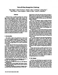
The line linking two inner eye corners (Eleft, Eright) is perpendicular to the y-z plane after registration, Figure 1(left). The facial symmetry plane P is perpendicular to both the x-y plane and the x-z plane while passing through nose tip Ntip, nose bottom Nbottom and top Ntop, Figure 1(left). The line linking the nose top Ntop and nose bottom Nbottom is perpendicular to the x-z plane, Figure 1(right).
Ntop is defined as the intersection of the line linking Eleft and Eright and plane P.
Fig. 1. Face in the canonical position after the registration
The only prior-knowledge we have before the registration stage is the location of the nose tip1. All rest features points, i.e. inner eye corners, top and bottom point of nose, are located simultaneously with the process of pose estimation. 1
The nose tip can be automatically located at the stage of raw data generation (via stereo matching process).
3D Face Recognition Based on Non-iterative Registration
789
Two stages are involved to obtain the rotation matrix R and facial features. The first stage is to estimate the initial rotation matrix (head pose) based on the symmetryproperty of a face. We start from locating the plane P (Figure 2a1) which is perpendicular to both the x-y plane and the x-z plane while passing through nose tip Ntip. The facial profile is then extracted by the intersection of the surface and plane P, in the form of a set of scattered points, on which a B-spline curve is fitted (Figure 2b1). The candidate nose saddle point and nose bottom point can be located via calculating the first and second curve derivatives. RX1 is estimated by the angle between the line linking the candidate nose saddle and bottom points and the x-y plane (Figure 2b1). Figure 2c1 (side view) and Figure 2a2 (frontal view) show the result after applying the rotation matrix RX1 on the original data D, i.e.
D1 = R X 1 * D
(2)
Similar technique is employed to estimate RY1 and RZ1. Briefly, plane M in Figure 2a2 is defined as being perpendicular to both the x-y plane and the y-z plane and passing through nose tip Ntip. The extracted facial profile is described by a B-Spline curve on which symmetric analysis is applied. Then RY1 (Figure 2b2) and RZ1 (Figure 2a3) are calculated. The result after applying rotation matrix RY1 on D1 is illustrated in Figure 2c2 (profile view) and Figure 2a3 (frontal view): D2 = RY 1 * D1 = RY 1 * R X 1 * D
(3)
The final result of stage 1 shown in Figure 2b3 (profile view) and 2c3 (frontal view) is calculated by: D3 = RZ 1 * D2 = RZ 1 * RY 1 * R X 1 * D = R1 * D
(4)
Now the probe face D is near frontal after being transformed by R1 (Figure 2c3). Next, since human faces are not perfect symmetric objects, and facial expressions also affect the symmetric measurement, the initial pose estimations need to be refined. Pose refinement uses the following rotation matrix:
R2 = R X 2 ⋅ RY 2 ⋅ RZ 2
(5)
where RX2, RY2 and RZ2 are the compensation rotation matrices around x, y and z axes. The key idea of pose refinement is to evaluate RX2, RY2 and RZ2 using facial feature points. Since the coordinates of these features are directly related to pose, refining process must be done in parallel with facial features detection. With the candidate nose saddle point estimated from stage 1, possible areas containing inner corners of the eyes can then be decided upon, as shown in Figure 3a. For each area, eight candidates of the inner eye corners are obtained for further consideration (Figure 3b). The pair of points with the highest priority value is chosen as the inner eye corners (Figure 3c). The calculation of the priority is conducted under the constrains which features points must satisfy when the face is in the canonical position. Elefti and Erighti denote ith pair of inner eye corners from 2×8 candidates. Corresponding Ntopi is calculated as: θ Zi 2 = a tan(
i i E left , y − E right , y i i E left , x − E right , x
)
(6)
790
Y. Song and L. Bai
(a1)
(b1)
(c1)
(a2)
(b2)
(c2)
(a3)
(b3)
(c3)
Fig. 2. Pose estimation i N top ,x =
i i i ( Eleft , x + R Z 2 (θ ) ⋅ E right , x )
(7)
2
i i P i = N top , x − RZ 2 (θ ) ⋅ N tip , x
(8)
The smaller the Pi, the higher priority the ith pair has. After Eleft and Eright have been decided, Ntop is to be calculated based on the constrains of 1) having the same y- value as Eleft and Eright; 2) locating on the facial profile created by the intersection of the symmetric plane P and the surface, which is represented by B-Spline curve; 3) xvalue is the mean of x- values of Eleft and Eright. i N top ,x =
( Eleft , x + RZ 2 (θ ) ⋅ E right , x )
(9)
2 m
N top , y = R y R z Eleft , y = R y R z E right , y = ∑ Bi , p ( s ′)C i , y
(10)
i =0
m
N top, z = ∑ Bi , p ( s ′)Ci , z i =0
(11)
3D Face Recognition Based on Non-iterative Registration
N bottom, x = N tip , x
791
(12)
m
N bottom, y = ∑ Bi , p (s′′)Ci , y
(13)
i =0
m
N bottom, z = ∑ Bi , p ( s ′′)Ci , z
(14)
Rz N top, z = Rz N bottom, z
(15)
i =0
m
Bi , p ( s )C i represents the face profile inferred from the facial symmetry plane. where ∑ i=0
(a)
(b)
(c)
Fig. 3. Pose estimation and facial features detection. (a) Output from the first stage of pose estimation. Possible areas containing the inner corner of eyes are decided upon. (b) Candidates of the inner eye corners chosen from the areas marked in (a). (c) Detected facial features and the final output from the pose estimation algorithm.
More experimental results of comparing our 3D registration methods with the ICP algorithm are given in Section 5. Two typical examples of ICP registration are shown in Figure 4b1 and 4b2. Figure 4c1 and 4c2 are the results using our approach.
(a1)
(b1)
(c1)
(a2)
(b2)
(c2)
Fig. 4. Comparison between ICP method and our proposed method. (a1) First pair of point clouds to be registered. (b1) Positive result from ICP method. (c1) The registration result using our approach. (a2) Second pair of input point clouds. (b2) Negative result from ICP algorithm. (c2) Our result.
792
Y. Song and L. Bai
4 3D Modeling As mentioned in the previous section, we aim to represent a complex object, e.g. a face, by a single B-Spline surface patch. This problem can be restated as follows: given an unstructured point cloud P: pi (xi, yi, zi), find a single B-Spline surface Γ which fits the point cloud best. A B-Spline surface is defined as the set of points that can be obtained by evaluating the following equation for all the parameter values of s and t: n
m
Γ( s, t ) = ∑∑ B j , g ( s )N i , h (t )C i , j = p cd
(16)
j =0 i = 0
C is a set of control points. Bj,g(s) is the B-Spline basis functions of degree g in the sdirection, defined over a sequence of distinguished values, known as the knot vector U={u0, u1, …, ul}: (17) if uj ≤ s