spatial representation of 3D locations in multimodal sensory space as well as an ... hierarchical spatial working memory based on the above for storage and ...
3D Hierarchical Spatial Representation and Memory of MultiModal Sensory Data Deepak Khosla, Paul A. Dow, David J. Huber HRL Laboratories LLC, Malibu, CA, USA ABSTRACT This paper describes an efficient method and system for representing, processing and understanding multi-modal sensory data. More specifically, it describes a computational method and system for how to process and remember multiple locations in multimodal sensory space (e.g., visual, auditory, somatosensory, etc.). The multimodal representation and memory is based on a biologically-inspired hierarchy of spatial representations implemented with novel analogues of real representations used in the human brain. The novelty of the work is in the computationally efficient and robust spatial representation of 3D locations in multimodal sensory space as well as an associated working memory for storage and recall of these representations at the desired level for goal-oriented action. We describe (1) A simple and efficient method for human-like hierarchical spatial representations of sensory data and how to associate, integrate and convert between these representations (head-centered coordinate system, body-centered coordinate, etc.); (2) a robust method for training and learning a mapping of points in multimodal sensory space (e.g., camera-visible object positions, location of auditory sources, etc.) to the above hierarchical spatial representations; and (3) a specification and implementation of a hierarchical spatial working memory based on the above for storage and recall at the desired level for goal-oriented action(s). This work is most useful for any machine or human-machine application that requires processing of multimodal sensory inputs, making sense of it from a spatial perspective (e.g., where is the sensory information coming from with respect to the machine and its parts) and then taking some goal-oriented action based on this spatial understanding. A multi-level spatial representation hierarchy means that heterogeneous sensory inputs (e.g., visual, auditory, somatosensory, etc.) can map onto the hierarchy at different levels. When controlling various machine/robot degrees of freedom, the desired movements and action can be computed from these different levels in the hierarchy. The most basic embodiment of this machine could be a pan-tilt camera system, an array of microphones, a machine with arm/hand like structure or/and a robot with some or all of the above capabilities. We describe the approach, system and present preliminary results on a real-robotic platform. Keywords: multimodal, sensory, fusion, spatial representation, vision, control, bio-inspired
1. INTRODUCTION This work pertains to machine or human-machine applications requiring efficient processing and memory of sensory data for goal-oriented action. It describes an efficient and robust method/system for processing and understanding of sensory data. More specifically, it describes a computational method and system for how to process and remember multiple locations in multimodal sensory space (e.g., visual, auditory, somatosensory, etc.). The multimodal representation and memory is based on a spatial hierarchy implemented with novel analogues of real representations used in the human brain. The primary contribution of our work is a core representation hierarchy that encodes the location of a target in space in terms of a camera system’s required orientation such that the target is centered in the camera images. This is easily thought of as an active vision robotic head with two independent cameras as eyes on a movable head. Thus the visual core of our multimodal hierarchy is based on the eye and head positions necessary to center a target in the incoming images. An additional contribution of our paper is a system for extending this core hierarchy to include multimodal sensor input, including auditory and somatosensory input. The paper also includes simple and versatile methods for incorporating targets encoded with our representations into a working memory. Finally, we discuss what is needed to
Multisensor, Multisource Information Fusion: Architectures, Algorithms, and Applications 2009, edited by Belur V. Dasarathy, Proc. of SPIE Vol. 7345, 73450O · © 2009 SPIE · CCC code: 0277-786X/09/$18 · doi: 10.1117/12.820363
Proc. of SPIE Vol. 7345 73450O-1
quickly and dynamically learn the mappings needed to traverse the representation hierarchy. Thus, if a system parameter changes, the system can adapt its mappings appropriately.
2. THE CORE REPRESENTATION HIERARCHY This work encompasses a spatial representation hierarchy that is invariant to movement. At the core is a vision-based hierarchy that can be extended to include representations in various other coordinate systems. The motivation for this is that different representations at different points in the hierarchy are needed for different goals. First of all, sensor data comes in different forms from different sources. The key differentiating aspect of these different input forms is the particular movements they are dependant on and invariant to. For example, auditory localization data is invariant to movements of eye cameras, arms, and other appendages, though the representation of a constant location will vary as the head moves. Although our work can encompass a variety of sensory input forms and hierarchy extensions, we have chosen to give it a stable core of a vision-based hierarchy. Other cores are possible, though we have chosen the visual hierarchy for several reasons. First of all, deduction of three-dimensional target locations is more accurate and robust with two-camera visual input that other sensory input types we have experimented with. Second, additional, higher-level processing is typically done in the visual realm, including recognition and identification. Target in ECC (eye-centered coordinates)
Target Representation
Head-centered map ECC
Target in HCC (head-centered coordinates)
Eye position
HCC Head position
BCC
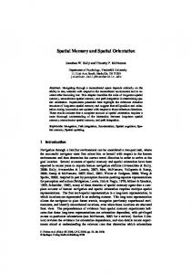
Body-centered map Target in BCC (body-centered coordinates) Figure 1: Constructing a Target Representation. This involves mapping the target in ECC to HCC and BCC. Additionally, the current position of the eyes in the head and the head on the body must be saved as well.
We begin our description of the core visual hierarchy by detailing the process by which a visually-identified target is inputted and constructed. Figure 1 shows how various maps are used to ascend the hierarchy and build a complete representation of the target. Notice that there are three levels to the core hierarchy: ECC, HCC, and BCC for eyecentered, head-centered, and body-centered coordinates, respectively. We will now describe the meaning of each of these levels and how they are constructed. The eye-centered coordinates (ECC) of a target are considered to be the primary input to the representation hierarchy. The idea is that a target is identified (in a system outside the scope of this paper) in terms of its pixel location in a left and right eye camera image. The x-y pixel coordinates in each image are combined to create a four-element vector. This is considered a representation of the target location in eye-centered coordinates. As long as the system does not move, i.e. neither the eyes nor the head move, this is an accurate representation of the three-dimensional target location in space. Unfortunately, as soon as either eye or the head moves, the specified pixel coordinates no longer correspond to the same location in space. This is why we need higher-level representations that are invariant to these movements. The second level in our core hierarchy is head-centered coordinates (HCC), which are based on the positions of the eye cameras required for the target location to be centered in both images. This representation is invariant to eye position, because, regardless of the current positions of the eyes, the HCC tells us how they would be positioned if the target was centered in the images. Our construction of HCC is based on that described by[1],[2],[3]. We assume that each of
Proc. of SPIE Vol. 7345 73450O-2
the joint angles are represented by a value from -1 to +1. For example, the pan angles of the eyes are -1 if the eyes are looking to the extreme left, and they are +1 is they are looking to the extreme right. They are looking straight ahead when the joint angle value is 0. Likewise, for tilt angles, -1 corresponds to looking down and +1 corresponds to looking up. Let ΘL and ΦL be the left eye pan and tilt, respectively, while the target is centered, and let ΘR and ΦR be the right eye pan and tilt, respectively. Borrowing notation from (Greve et al. 1993; Grossberg et al. 1993; Guenther et al. 1994), we will represent the HCC as a four element vector H = h1 , h3 , h5 , h7 . The elements h1 and h3 correspond to a head-centered, ego-centric pan and tilt, respectively. They are computed as follows.
ΘL + ΘR 2 Φ + ΦR h3 = L 2 h1 =
These give the pan and tilt of a line coming out of the midpoint between the eyes and going straight to the target. Notice that h1 and h3 will also be between -1 and +1, with the same meaning as the eye angles. While this makes up part of the information needed to represent the target’s location, there are still infinitely many points on this line where the target could reside. To represent the distance of the target from the robot, we use a representation of the vergence angle. That is, the angle at which the central focus of the two eyes converge. Again, this is similar to[1],[2],[3]. Thus, h5 and h7 represent the horizontal and vertical vergence, respectively, and they are computed as follows.
ΘL − ΘR 2 ΦL − ΦR h7 = 2 h5 =
Again, notice that h5 and h7 can vary from -1 to +1, except that not all of this range will be realistically achieved when both eyes are looking at the same target. This is because, for example, h5 = −1 means the left eye is looking totally to the left, and the right eye is looking totally to the right. Clearly, they will not be verging in this case. While the equations given above are sufficient to calculate the HCC representation of a target that the robot is looking directly at, we need to find the HCC of any target visible to both eyes. Thus, in order to correctly determine the HCC representation of any ECC representation we describe a method for learning a mapping that, given the ECC
ˆ be the representation of a target produces an offset from the HCC of the target the robot is currently looking at. Let E
ˆ is the HCC ECC representation of the target, H is the HCC representation of the currently foveated point, and H
ˆ that we are trying to compute. The mapping hmap (head-centered map in Figure 1) is used to representation of E compute the value we want as follows. ˆ = hmap(E ˆ)+H H The details of how we learn hmap will be discussed later. Now we will describe how the final level in the core representation hierarchy.
The third level in the core representation hierarchy corresponded to body-centered coordinates (BCC), which is based on the head position and eye vergence necessary to center the target in both images while the eyes are looking as straight ahead as possible. we can easily compute the BCC of a target if both eyes are looking at it and a line coming straight out of the midpoint between the eyes intersects the target. Recall that a line originating from the midpoint between the eyes is how we defined h1 and h3 . Thus, we can directly compute the BCC of a target if both eyes are looking at it, h1 = 0
Proc. of SPIE Vol. 7345 73450O-3
and h3 = 0 . Like HCC, BCC is represented by a four-element vector B = b1 , b3 , b5 , b7 . Let ΘH and ΦH be the head joint’s pan and tilt, respectively. Assuming that the target is centered in both eyes, h1 = 0 , and h3 = 0 , we compute BCC as follows. Auditory Extension
Core Visual Hierarchy
Auditory HCC
Somatosensory Extension
ECC
Hand-CC
Eye position
Hand position
HCC
Arm-CC
Head position
Arm position
BCC
BCC
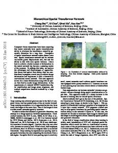
Figure 2: Multimodal extensions to the core representation hierarchy. Different sensory input types interface with the core hierarchy at different levels.
b1 = Θ H b3 = Φ H b5 = h5 b7 = h7 b h = 0. Notice that b1 and 3 are the head angles needed so that the eyes can center the target while h1 = 0 , and 3 b
b
Also, 5 and 7 are the same as regardless of the head position.
h5 and h7 , because the vergence angle and distance to the target are the same,
The equations given above tell us how to compute the BCC of a target when it is directly in front of the robots face. What we really want, is a way to compute the BCC of any target for which we know the HCC. To do this, again, we need to learn a mapping. Like with HCC, we will map to an offset of the BCC of the location the robot is currently looking at. This time though, we do not assume that the head’s pan and tilt angles are independent. The result of this is that the map we will learn takes as its inputs the target’s HCC as well as the current head pan and tilt. This allows for
ˆ different mappings depending upon the current head position. Let H be the HCC of the target, let B be the BCC of the
ˆ
current position, and let B be the BCC representation of the new target. The mapping, bmap (body-centered map in Figure 1), gives us the value we need. We will describe how bmap is learned in Section 5.
Bˆ = bmap(H, b1 , b3 ) + B 3. MULTIMODAL EXTENSIONS TO THE HIERARCHY While the core hierarchy is constructed and interpreted in terms of visual input and joint angles required to visually center a target, it can easily be extended to incorporate sensory data from disparate sources. Figure 2 shows a sample of how auditory and somatosensory data can contribute to a rich, multimodal representation hierarchy. Just as mappings were used to ascend the core visual hierarchy, additional mappings are used to attach heterogeneous sensor data to the core. The details of how auditory and somatosensory data are gathered and processed are beyond the scope of this paper, though, in this section, we will describe how they can be interfaced to the core visual hierarchy.
Proc. of SPIE Vol. 7345 73450O-4
Auditory localization is frequently accomplished with two microphones as ears fixed to a robotic head. Techniques exist for determining horizontal and vertical offset angles of a target source, originating from the center of the robot’s head. This “head-centered” coordinate representation is different from the HCC used in our core hierarchy. For one, it does not inherently relate to eye positions. Also, it does not contain information about the distance to the target. Thus to transform a target represented in this auditory HCC to our core HCC an estimate of distance and a mapping is required. Recall the h1 and h3 in the core HCC relate to the horizontal and vertical joint angles of the eyes. Clearly a mapping can easily be learned that transforms the auditory angles into h1 and h3 . If the auditory system has a way to estimate target distance, a mapping can also be learned to convert that to h5 and h7 . Alternatively, these variables can be given uncertain initial estimates to be updated when more information is acquired. For example, they can be initially estimated to be some reasonable distance away. Then the robot can be instructed to look at that estimated target. Once it becomes visible these values can be updated. Another possible extension of the hierarchy is to incorporate a complete somatosensory hierarchy at the bodycentered level. The idea here is that, through similar means, a complete hierarchy is constructed that represents the position of a target relative to a hand, an arm, and the center of the body. The body-centered coordinate here is not based in the joint angles required to see a target, but instead the joint angles required to touch or point to a target. By both looking at and touching a target simultaneously, a mapping can be learned that converts between these two disparate body-centered coordinate systems. By building accurate mappings to and from extensions of the core hierarchy, we are able to store a simple representation of a target and yet transform it into whatever representation is required for a given application. This also allows the various joints to be moved without losing information about the target’s whereabouts.
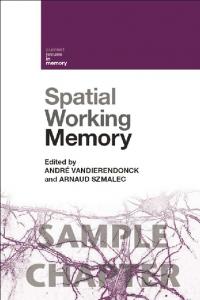
4. WORKING MEMORY An important quality of our hierarchical spatial representation is the ease with which is can be stored into a working memory system. The point of the hierarchical spatial working memory (HSWM) is to store a representation of any targets that have been recently identified and are relevant to future actions or processing. For example, if a number of salient target are identified at one point, the HSWM can be used to look at each of them in turn. The HSWM can be fitted to different tasks by basing it on different fundamental data structures. If an urgency function that maps targets to urgency values is defined, it can be used to sort a priority queue of existing targets. Figure 3 shows an example of how a priority queue-based HSWM would work. Additionally, decay can be set that will allow targets to be forgotten after some amount of time. There are a set of queries and operations of the HSWM that can be useful. First and foremost is a pop functionality that returns a target from the HSWM, as is shown in Figure 3. This target can be the focus of some action, such as looking at or grabbing it. An example of the movements that need to be computed to look at the target is shown in Error! Reference source not found.Error! Reference source not found.. In this example, we use the BCC target representation to compute the pan and tilt of the head and each eye. Clearly this can be adapted for robots with a somewhat different joint configuration. The resulting joint angles, once the movements are made, should have the robot looking at the target, with the center of its head (say, where the nose would be) pointing directly at the target. The eyes will also be verging onto the target. Another important query is the ability to traverse the representation hierarchy for targets in the HSWM. This can be used to identify the current ECC of targets in the HSWM. An estimate of the location of a target corresponds to the eyecentered coordinate representation given the current positions of the robot’s eyes and head. Thus, if the robot’s eyes and head have not moved since a given target was initially identified, then the stored ECC is sufficient. In most cases, the targets stored in working memory will have been identified with many different eye and head positions. Figure 4 illustrates how the current ECC of these targets can be computed. Since BCC is invariant to both eye and head movements, this value is stable and is the place where the conversion begins. If the stored head position is different than the current head position, because the head has moved since the target was identified, then the HCC representation of the target must be updated. This is done with an inverse mapping from BCC to HCC. This up-to-date HCC is now stored along with the current head position. Next, an inverse mapping from HCC to ECC updates the ECC representation as well as the current eye position. If the target’s ECC falls within the eye camera images’ pixel range, then the target is
Proc. of SPIE Vol. 7345 73450O-5
currently visible to the robot. When visible, these pixel coordinates are outputted so that they can be used as described above. If they are not visible, then it simple reports this fact. The function hmap maps from 4-dimensional input, the ECC representation of a target, to a 4-dimensional output, the HCC offset from the current HCC. The function bmap maps from 6-dimensional input, the target’s HCC and the current head position, to a 4-dimensional output, the BCC offset from the current BCC. We use LWPR to learn these maps by using the maps (untrained at first) to generate output estimates. The robot then moves such that the actual HCC or BCC can be computed (by looking straight at the target). Given the initial estimate and the actual answer, this training point is inputted into LWPR which improves the mapping. By doing this many times, the mapping converges on the correct mapping. Now we will describe the training scenarios for learning the mappings quickly.
ECC
ECC
Eye position
Eye position
HCC
HCC
Head position
BCC
Target 1
Head position
BCC
Target 2 Most urgent target is removed from priority queue
Target 3 Target 4 …
New target is inserted into priority queue
Figure 3: Hierarchical spatial working memory implemented with a priority queue. A new target is inserted at the proper place in the queue. The highest-priority target is removed.
A fundamental tool of the training scenarios is the ability to identify a target in the eye camera images after a small eye or head movement. This allows us, without knowing how to foveate directly to a target, to move the eyes or head a little in the direction of the target and identify how far it has to go and whether it has foveated the target. To do this we employ normalized cross correlation. When a target is identified and patch of pixels is grabbed from the image. After the movement, normalized cross correlation is used to find that patch in the new images. Another necessary tool is a simple controller for foveating the target. Since before the mappings are trained the robot cannot foveate directly to the target, a simple linear controller can be used to move the eyes or head in the right direction. Basically, at one step the target is identified and a move is generated. Then normalized cross correlation is used to find the target again. The controller can now take a larger or smaller step depending on whether the target was over- or undershot. The scenario for training hmap attempts to make many predictions and, therefore, generates many training points for the LWPR map in a short time. The scenario begins by choosing many targets at random from the visible area, and estimating the HCC of each target with the current map. Then one target is chosen and the linear controller is used to foveate that target. When the target is successfully foveated, the LWPR map is updated with the training point of the target’s estimated and actual HCC. Then the scenario proceeds to pick another random target and estimate the HCC of that target and all of the previously generated targets. Once again, a target as chosen and the linear controller is used to foveate it. And again, once foveated the LWPR map is updated, although now there will be multiple training points: one for each time the target’s HCC was estimated. The slowest part of this loop is the time it takes the linear controller to foveate the target. The benefit of this scenario is that it is able to gather many training data points each time it foveates a target.
5. LEARNING MAPPINGS BETWEEN REPRESENTATIONS To traverse the representation hierarchy mappings must be learned between adjacent representations. There are a variety of existing machine learning techniques that can be used. We center our discussion on an online learning method
Proc. of SPIE Vol. 7345 73450O-6
called locally weighted projection regression (LWPR). LWPR was created by[4]. Really any online learning method that can learn functions with the dimensions that we require will suffice as a black box learning method for our purposes. Thus, when we refer to LWPR, it is acceptable to substitute another qualifying learning method. Our discussion will focus on the mappings required for the core vision-based representation hierarchy, though the same techniques can easily be analogized to map to and from the extensions discussed earlier. All that is needed is a scenario that supplies numerous data points including the extension representation and the corresponding coordinate representation from the core hierarchy. Also, these mappings can be updated dynamically. During the course of normal operation, any time the coordinates can be directly computed for two adjacent representations in the hierarchy, that data can be used as a training point. Targets in priority queue
Locations of targets currently visible
T1
Update ECC if eyes have moved
T1: (xL,yL,xR,yR)
T2
ECC
T2: (xL,yL,xR,yR)
T3
Eye position
T4
HCC
T5
Head position
Update HCC if head has moved
BCC
T3: not visible T4: (xL,yL,xR,yR) T5: not visible
Figure 4: Generating pixel location predictions of targets in working memory. This involves ensuring that the ECC representation of each target is up-to-date and, if the target is visible, returning the ECC target representation.
A similar scenario is used to generate training data for bmap. The difference is that the head and eyes are moved with different controllers. Basically the head controller moves the head a little and then the eye controller runs until the eyes foveate the target. Now an estimate of the BCC is made. This is followed by another head movement, another foveation, and another estimate. Thus continues until the robot is looking directly at the target and the actual BCC can be computed. The LWPR map is then updated with a training point from each time the head was moved.
6. CONCLUSION This work pertains to machine or human-machine applications requiring efficient processing and memory of sensory data for goal-oriented action. It describes an efficient and robust method/system for processing and understanding of sensory data. More specifically, it describes a computational method and system for how to process and remember multiple locations in multimodal sensory space (e.g., visual, auditory, somatosensory, etc.). The multimodal representation and memory is based on a spatial hierarchy implemented with novel analogues of real representations used in the human brain. The novelty of this work is in the computationally efficient and robust spatial representation of locations in multimodal sensory space as well as an associated working memory for storage and recall of these representations at the desired level for goal-oriented action. More specifically, the novel contributions are (1) A simple and efficient method for human-like hierarchical spatial representations of sensory data and how to associate, integrate and convert between these representations (head-centered coordinate system, body-centered coordinate, etc.), (2) A robust method for training and learning a mapping of points in multimodal sensory space (e.g., camera-visible object positions, location of auditory sources, etc.) to the above hierarchical spatial representations, and (3) A specification and implementation of a hierarchical spatial working memory (HSWM) based on the above for storage and recall at the desired level for goal-oriented action(s).
REFERENCES [1]
Greve, D., S. Grossberg, F. Guenther, and D. Bullock., "Neural representations for sensory-motor control. I: Headcentered 3-D target positions from opponent eye commands," Acta Psychol (Amst) 82, no. 1-3, 115-38 (1993).
Proc. of SPIE Vol. 7345 73450O-7
[2] [3] [4]
Grossberg, S., F. Guenther, D. Bullock, and D. Greve., "Neural representations for sensory-motor control, II: learning a head-centered visuomotor representation of 3-D target position," Neural Networks 6, no. 1, 43-67 (1993).. Guenther, F., D. Bullock, D. Greve, and S. Grossberg., "Neural Representations for Sensory-Motor Control, III: Learning a Body-Centered Representa tion of a Three-Dimensional Target Position," Journal of Cognitive Neuroscience 6, no. 4, 341-358 (1994). Vijayakumar, S., A. D'Souza, T. Shibata, J. Conradt, and S. Schaal., "Statistical Learning for Humanoid Robots," Autonomous Robots 12, no. 1, 55-69 (2002).
Proc. of SPIE Vol. 7345 73450O-8