Multimedia Development Center. Matsushita ... streaming and data compression can be considered indispensable. In previous .... We call definition information.
A Spatial Hierarchical Compression Method for 3D Streaming Animation Toshiki Hijiri, Kazuhiro Nishitani, Tim Cornish, Toshiya Naka and Shigeo Asahara Multimedia Development Center Matsushita Electric Industrial Co., Ltd. 1006, Kadoma, Kadoma-City, Osaka, 571-8501, Japan {hijiri, nisitani, tim, naka, asahara}@isl.mei.co.jp
ABSTRACT
real-time distribution of video and audio data on the internet.
When distributing 3D contents real-time over a network with a narrow bandwidth such as a telephone line, methods for streaming and data compression can be considered indispensable.
With regard to the distribution of 3D data, VRML97 [5, 14], which forms the base of Web3D technology, has already been standardized, and as an extension of this there is also 3D Streaming Technology, with the VRML Streaming WG of the Web3D Consortium [1, 15] preparing a draft report on 3D streaming.
In previous work, we made possible the real-time streaming of 3D animation data on a network with a narrow bandwidth such as a telephone line by partitioning motion data for humanoid characters (data obtained by motion capture, for example full frame data at 30 frames/sec) into packets and then carrying out compression by culling data along the time axis.
We devised a Motion Data Streaming Method [11], which divides humanoid character1 motion data conforming to VRML Humanoid Animation Version 1.1 [2] (currently being proposed for standardization by the H-Anim WG) into packets, and then compresses and transmits those packets, and have developed a client/server system for this purpose. Using this system it becomes possible to realize the transmission and playback of 3D character animation with minimum time lag, even on a network with a narrow bandwidth such as a telephone line.
However, as a 3D scene becomes more complex, the number of humanoid characters also increases. Accordingly, the transmission rate also increases, becoming greater than the available bandwidth and making real-time distribution impossible. In this paper, we concentrate on the problem of real-time distribution, describing a new data packet format which allows flexible scalability of the transmission rate, and a data compression method, SHCM, which maximizes the features of this format using a 3D scene structure.
However, in the case of contents where a number of characters appear, the bandwidth of a telephone line proves to be insufficient and real-time transmission becomes impossible. In order to solve this problem, we considered how to even further optimize the data for any one character, and how to optimize data for a number of characters based on their relative spatial positions.
Because compression using a 3D scene structure aims to obtain the optimal overall compression rate by altering the compression rate for each object, based on information on the position in 3D space relative to the behavior (motion) data of each object, its application to MPEG4 can be expected.
In this paper, we describe a method for data optimization, the Spatial Hierarchical Compression Method (SHCM), which, when data has been divided into packets using existing technology, makes real-time transmission in a limited bandwidth possible for contents with a packet size that is greater than the available bandwidth.
Using this method the real-time distribution of 3D contents becomes possible despite the bandwidth restrictions of an ordinary telephone line.
Section 2 describes 3D Streaming Animation. Section 3 describes the SHCM and then an example implementation is given and relevant issues discussed in Section 4. Our conclusions are presented in Section 5.
Keywords streaming, animation, VRML, humanoid character, hierarchy, compression
1. INTRODUCTION
2. 3D Streaming Animation 2.1 Related Work
In recent years, streaming technology has grown in usage for the
Currently, as MPEG4/Web3D Convergence Plan [13], the technologies such as Face and body animation, Binary format, 3D hierarchical mesh coding, etc. are widely evaluated. In concrete work,
Permission to make digital or hard copies of part of all of this work or personal or classroom use is granted without fee provided that copies are not made or distributed for profit or commercial advantage and that copies bear this notice and the full citation on the first page. To copy otherwise, to republish, to post on servers, or to redistribute to lists, requires prior specific permission and/or a fee.
1
VRML 2000, Monterey, CA USA © ACM 2000 1-58113-211-5/00/02 … $5.00
95
“ character” means “ humanoid character” , not “ text character” in this paper.
MAGNET: the compression capabilities in MPEG and binary encoding for VRML [6].
"Animation Data" to mean all the data necessary to generate an animation scene such as information on position, rotation, scale, position of viewpoint, light sources etc.
MetaStream: a framework for the storage of multiresolution 3D models including associated geometry and texture data [12].
(3) Audio Data:
These two technologies are providing sufficient functionality for the static object encoding such as 3D scene, geometry, texture, etc. On the other hand, the method mentioned in this paper is providing functionality for the dynamic data such as animation data (corresponding to the data of Interpolator node in VRML97 expression). We think that MPEG4/Web3D Streaming Animation technology will be able to be improved by collaborating these two technologies.
We use, as an example, the de facto standard RealAudio (Developed by RealNetworks [9]) which allows high quality audio even with a low bitrate, however, there is no restriction and other audio streams may be used [7, 8].
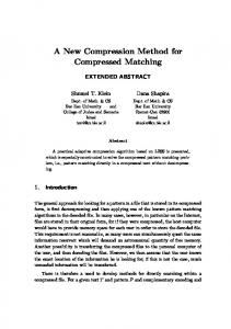
2.3 Overview of Animation Data Transmission The overall flow of animation data from transmission to rendering is represented in Figure 2.
2.2 Classification of Contents Data
At the client, compressed data packets being sent from the server are buffered, and then the data is decompressed using linear, spline or other interpolation methods. It is then rendered, using time stamps attached to the packets to ensure synchronization with audio data. Our system is implemented with extensions to RealSystemG2 (by RealNetworks [9]). This utilizes RTSP (Real Time Streaming Protocol) [4] whose delivery mechanisms based on RTP (RealTime Transport Protocol) [3]. Therefore, by multiplexing the structure of the data packets, while retaining scalability, data transfer can continue in real-time, even with a dynamically changing transmission bandwidth. Operations involving the time line, such as fast forward, rewind, pause etc. can be carried out at the client side.
The data that makes up a 3D scene can be classified as static data or dynamic data. The latter can be considered a suitable object for real-time transmission as a 3D stream. This data is further classified as (1) unsequential Structural Data, (2) sequential Animation Data and (3) Audio Data (See Figure 1).
1. Shape Data File 3D Content File
2. Animation Data File 3. Audio Data File
Position Rotation Scale Camera Lighting etc.
Figure 1: Classification of 3D Contents Data
2.4 Animation Data File Format (1) Structural Data:
The file for (2), the Animation Data (as classified in 2.1) is divided into a Header Part and a Data Part (See Figure 3). Section 2.4.1 describes the Header Part and 2.4.2 the Data Part in more detail.
This is needed before the animation begins, and is therefore downloaded initially and stored on the client. (2) Animation Data: This is our main interest. The file format used is described in detail in Section 2.4. In this paper we use
3D Content Data Converter Animation Data (High rate) Animation Data (Middle rate) Animation Data (Low rate)
Shape Data Buffering Process
Internet (RTSP)
Decompression Process Synchronous Playing
Buffering Process
Audio Data
Decompression Process
Client
Server Figure 2: Flow of Processing of Animation Data to Rendering
96
Header Part
that are subsequently transmitted can be interpreted. However, because channel data that fails Channel Authentication subsequently cannot be received, caution is necessary.
Data Part
Stream Info. Channel Info. DAT
… DAT DES DAT … DAT
(DAT : Data Packet, DES : Description Packet)
2.4.2 Data Part As described in the previous section, in the Data Part there are Data Packets with the Animation Data, and Description Packets with the Channel Tables.
Figure 3: Animation Data File Format
2.4.1 Header Part
Data Packets are constructed with information about the number of channels in that data packet first, and then the data for each of those channels follows. Similarly, for each channel, first there is information on the number of frames, then the animation data for each of those frames follows.
This section describes the Header Part, which contains information that must be transmitted before the streaming starts. The Header Part is further divided into Stream Information and Channel Information. The main part of the Stream Information is the offset value from the start of the file that indicates the address of the start of the Data Part, the length of the Data Part, the number of packets in the Data Part, the average and largest packet size of the Data Part, etc. Also included here as necessary are version information, the size of the Header Part etc.
When represented graphically, a 2D array structure is formed with the number of channels and the number of frames as the axes (Figure 5). The aim of this paper is to describe how, with this structure, it becomes possible to alter the size of each packet. This packet size is actually determined according to the target bandwidth by “ optimally apportioning weight of compression between the temporal domain and the spatial domain” , however, this will be explained in detail in Section 3.
The Channel Information contains information for the definition of all channels that will carry the Data Packets of the Data Part. What we mean by "Channel" in this paper corresponds to an Interpolator Node of VRML97 (PositionInterpolator, OrientationInterpolator, ScalarInterpolator, etc.) and is one type of Animation Data in this paper. We call definition information for these channels together a "Channel Table".
In Figure 5, Emn is the Animation Data - in VRML97 notation it is data for SFVec3f, SFRotation etc. The number of channels M is an optional value fulfilling the condition that it is less than the total number of channels (TC) defined in the Channel Table. The number of frames for each channel can also be explicitly set. In this way, because the size of the vertical and horizontal axes can be explicitly set, the packet size as a whole can also be explicitly set.
In the Data Part there are Data Packets with Animation Data and Description Packets with the Channel Tables (details are given in 2.3.2). At the start of the Channel Information is the total number of channels with Data Packets to be transmitted (TC), then channel definitions for each of those channels. The definitions for each channel are given below (Figure 4).
Time domain
0 ~ TC
Spatial domain
Channel Type 0 Parent Object Name Length 0 Parent Object Name 0 Object Name Length 0 Object Name 0 (TC : Total number of Channels)
Figure 4: Channel Table
Channel Number
Channel Number 0
0 1 : :
Frame Number …… 0 1 E00 E01 … … E10 E11 … … : :
: :
M EM0 EM1
…… ……
(Emn : Animation Data) In Figure 4, Channel Number is an ID number, Channel Type is a predetermined type number to distinguish position, rotation and scaling information of an object, or viewpoint information etc. Below that, Length of Parent Object Name and Name are the length of the object's name and the name itself.
Figure 5: Structure of Data Packet A Description Packet is a packet that is transmitted in the case that the existing Channel Tables should be altered. After a Description Packet has been transmitted, the animation should continue according to this new Channel Table. In the case of a very large number of channels, and when it is clear that the necessary channel structure will change greatly during transmission according to the scene being broadcast, the need to define all the channels at the start disappears, and it becomes
The client viewer, using the Object Name defined in each channel and its Parent Object Name, finds by name corresponding nodes in the already loaded Structural Data and establishes correspondences between them. We call this "Channel Authentication". Using this Channel Authentication, Data Packets
97
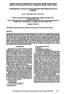
64 kbps
possible to reduce the size of the Header Part. Also, during a live broadcast, when a new object is suddenly introduced, it is possible to add a channel for that object. However, Description Packets are normally transmitted infrequently, and if there is no need to alter the Channel Table during the broadcast, it does not have to be transmitted at all.
(ISDN-1ch)
Data Size
56 kbps 28.8 kbps
2.5 Data Packet Creation Method
Time (sec)
Generally, animation data for 3D contents is expressed as keyframe data. This section explains our method of creating the Data Packets described in Section 2.4 based on this keyframe data.
Figure 7: Size of the Created Data Packets
3.1 Prioritization of Channels in the Packet
(DAT : Data Packet)
DAT 1
DAT 0
DAT 2
DAT 4
DAT 3
When Data Packets are compressed, the data is not compressed equally for all channels in the data packet – rather spatial priorities are assigned and data compression carried out according to this. When deciding these priorities, the “ hierarchical structure of the character” and “ relative position
: Original
Keyframe Data Data in Data Packet
Data Value
: Frame
of characters” are used. This is SHCM. This section explains this method of deciding prioritization in detail.
3.1.1 Using the Character’ s Hierarchical Structure
0
1
2
3
4
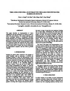
As an example a Humanoid Character based on the VRML Humanoid Animation Version 1.1 definition such as that shown in Figure 8 will be used. A Humanoid Character such as that in Figure 8 has a hierarchical structure as shown in Figure 9. With this Humanoid Character as an example, this section describes our prioritization method, concentrating on just one channel of the Humanoid Character.
5
Time (sec) Figure 6: Frame Data Creation Method in Data Packet
In the case of a hierarchical structure such as that in Figure 9, prioritization is decided simply by the depth of the structure starting at the root and decreasing towards the leaf nodes. The reason for this is that usually, for a Humanoid Character, the character’ s motions and is therefore the most important node. On the other hand, as you move out to the extremities, such as hands and feet, it is often the case that importance of motions is not high. Therefore, in the hierarchical structure in Figure 9, priorities are set as highest at the top, and decrease as you descend the levels. In concrete terms, for a Humanoid Character, this means that accuracy is sacrificed first at the fingers and toes, then working level by level back up the hierarchy as necessary.
Keyframe data is simply divided up into time units, and Data Packets created. In this paper, for the same of simplicity, 1 Data Packet is taken to represent data for 1 second. This is shown in graphical form in Figure 6. In Figure 6, the original keyframe data for the 3D contents is linearly interpolated data. Based on this data, the frame data at the border between data packets is determined by a calculation from the original keyframe data on both sides. The frame data of each Data Packet is the data calculated for each edge and the original key frame data in between. The reason for adding data for each edge to the data packet is that in order to be able to render data packets from anywhere along the time line, each data packet is handled as a piece of independent data. Also, even when the interpolation method is not linear, for example with spline interpolation, the method of creation of the Data Packet is the same.
skullbase vc7 vt12
r_shoulder
l_shoulder
r_elbow
3. SHCM (Spatial Hierarchical Compression Method)
l_elbow sacroiliac l_wrist
r_wrist
If Data Packets are created using the method described in Section 2.5, a file with a data size such as shown in Figure 7 will be created. In this case, with connection to a 28.8kbps or 56kbps telephone line, the shaded part exceeds the transmission bandwidth, so realtime distribution of the Data Packets is not possible. This section describes a Data Packet optimization method, SHCM, which is effective in such a case.
r_hip r_knee
r_ankle
l_hip Humanoid Root
l_knee
l_ankle
Figure 8: Example Humanoid Character
98
Local Priority 1
sacroiliac
3.2 Data Compression Method for Each Channel As described in Section 3.1, once a priority has been decided for all channels, data size is reduced for channels whose FP is low by culling frame rate data along the time axis in Data Packets. In actual fact, first, starting with the channel that has the lowest priority, frame rate is reduced by 1. If this exceeds the bandwidth of the transmission being attempted at that time, the frame rate of the channel with the lowest priority is again reduced by 1, so a total of 2, and the frame rate of the channel with the next lowest priority is decreased by 1. This operation is continued until the transmission fits the available bandwidth. One important note is that the frame data for either side of the time axis in the Data Packet should not be deleted. If only these two points remain, they should not be deleted. This is because, as we explained in Section 2.5, in order to make each Data Packet independent data, connection between the outer edges of any two Data Packets must be assured. The result of carrying out this series of actions is shown as an example of the Data Packet created in Figure 11. In this way, by reducing the number of frame data, based on the FP value for each channel, the size of the Data Packet can be reduced.
2 vt12
r_hip
l_hip
r_knee
l_knee
r_shoulder
l_shoulder
vc7
4
r_ankle
l_ankle
r_elbow
l_elbow
skullbase
5
r_wrist
l_wrist
3
6
Figure 9: Example of Humanoid’ s Hierarchical Structure Because we only decide priorities for one character, not the scene as a whole, we call this “ Local Priority (LP)” .
3.1.2 Using the Relative Position of Characters This section describes a method to decide priorities when there are multiple characters in a scene, using relative positions relating to the basis of the point of view. The distance between the viewpoint and HumanoidRoot of each Humanoid Character is calculated and priorities decided according to proximity to the viewpoint. That is, the priority of the character closest to the viewpoint is the highest and decreases as you go further away. Priorities are decided using the characteristic of human sight that the relation between distance and priority is logarithmic (perception decreases with distance by ln (natural log) [10]) (See Figure 10).
2
Time domain FP
C
B Character
GP
A B C
1 2 3
0
3 Spatial domain
1 A
0 User’s Eye
When the number of channels is huge, and even if the number of frame data for all channels is 2, and the transmission still exceeds the available bandwidth, starting with the data of the channel with the lowest priority, that data is deleted from the Data Packet and the transmission suppressed to within the available bandwidth.
Channel Number
HumanoidRoot
Humanoid Root Position Humanoid Root Rotation sacroiliac Rotation
) 1 E00 ) 1 E10 ) 2 E20
0( 1( 2( : :
M(
: : l_wrist Rotation
: :
Frame Number …… 1 …… N …… E01 E0N E11 … … E21 … … : :
) 6 EM0 EM1
(FP : Final Priority, Emn : Animation Data) (GP : Global Priority)
Figure 11: Data Packet after Optimization
Figure 10: Prioritization According to Relative Position of Characters
3.3 Correction of Final Priority As described in Section 3.1, priorities for channels are decided, and as described in Section 3.2 Data Packets are compressed. It is conceivable that the resultant animation scene is vastly different from the original. In this case, using a Data Conversion Tool, the user, while constantly checking the animation scene, can correct by hand the Final Priority of the channels that they think are most different.
This relates to the scene as a whole and is therefore called “ Global Priority (GP)” .
3.1.3 Final Prioritization As described in Sections 3.1.1 and 3.1.2, LP and GP are decided and their sum calculated for each channel. The result is called the “ Final Priority” . For example, taking character A in Figure 10 as having the hierarchical structure shown in Figure 9, the priority of the channel for vt12 (position, rotational angle, scale etc.) is that GP is 1, and LP is 3, so FP is 4. In this way a FP prioritization is decided for all channels.
99
4. Example Implementation and Discussion 4.1 Example Implementation This section describes an example implementation of 3D Streaming Animation, the VRML contents “ Lovely Mimi” (Table 1, Figure 12). Table 1: Contents Information
Playback Time [minutes]
1
Total Number of Channels [ch] (Total Number of Interpolator Nodes)
99
Number of Characters
4
Character A (mimi) [ch]
29
Character B (small mimi) [ch]
23
Character C (roach) [ch]
21
Character D (mouse) [ch]
11
Number of Non-Characters [ch] (slippers, kettle etc.)
Figure 12(a): 3D Streaming Manga “ LovelyMimi”
2
12
( ch: Number of Channels ) Using the packet creation method described in Section 2.5, a Stream Data File is created. The target transmission bandwidth for this example is assumed to be a 33.6kbps modem. In this case, we assume that a bandwidth of 25kbps can be used for data transmission. Making allowances for the audio stream (RealAudio), a file is created with 3 levels of scalability with 3D Animation Data transmission rates at 18kbps, 14kbps and 10kbps. This is optimized with a SHCM converter tool and the user carries out fine tuning on the resultant file with a stream editor.
Figure 12(b): 3D Streaming Manga “ LovelyMimi”
The file created is transmitted using RTSP from the server (RealServerG2) to the player (RealPlayerG2) along with the RealAudio file, and the 3D Streaming Animation can then be played.
methods using dynamic information such as, for example, the degree of change in animation data for each unit of time. Moreover, while in this paper we have talked about the case of several Humanoid Characters in a scene, this technique can be applied to any 3D contents with a 3D scene structure.
4.2 Discussion As the bit-rate decreases, the accuracy of movements of the hands and feet also decreases, as their LP priority in the hierarchical structure of the humanoid character has been set as low. However, as regards the animation of the character as a whole, because a balance of animation quality is maintained, this can almost be disregarded. Of course, in this case also, as the size of all the data packets is contained within the transmission bandwidth, continuous playback is possible without having to break part way through.
5. Conclusion In this paper, we have described a new 3D Streaming Animation Compression Method, SHCM. Using this technology, with 3D contents that does not require high quality animation, such as that for entertainment, even when several characters exist and the transmission rate exceeds the bandwidth, real-time distribution is possible, dynamically adapting to the bandwidth. As a result, content creators do not need to worry about bandwidth, and users can enjoy 3D streaming animation over a network with a consumer-available bandwidth such as 33k modems. Because of this, the handling of 3D contents on the Internet becomes easier, and a contribution can be made to the spread of Web3D.
As regards the method for determining the priority of each channel, because the number of components that depend on individual contents is very large, support by the user is necessary and this is a great burden for the user. In future research we will further add to the conditions used in determining priorities for the SHCM in the hope of raising its accuracy. Apart from the static information described in this paper, such as position and object hierarchies, it is necessary to also consider priority determination
2
100
Content “ LovelyMimi” created by Shout Interactive.
[15] Web3D Consortium - VRML Streaming WG. http://www.web3d.org/WorkingGroups/vrml-streams/.
Furthermore, by widening the scope of application beyond that of the PC and Internet, it becomes possible to implement this easily in digital broadcasting (Broadcast Cable, STB), portable devices etc. and it also forms core technology for game distribution systems etc. As future work, we need to investigate the compression of structural data downloaded before animation begins, and the streaming of that structural data itself. And we would like to form contacts with the MPEG4/Web3D Work for liaison.
6. ACKNOWLEDGMENTS The authors would like to thank all the reviewers of this paper. A special thanks to Yoshiyuki Mochizuki, who gave us many meaningful advice, and Michiharu Katsuda, who helped us to make sample programs. Finally thanks to the Multimedia Development Center of Matsushita Electric Industrial Co., Ltd., for giving us the opportunity for this type of creative work.
7. REFERENCES [1] Bernie Roehl, “ Draft Proposal for the VRML Streaming Working Group – (DRAFT) Version 0.1” , 1998. http://ece.uwaterloo.ca:80/~broehl/streams/proposal.html. [2] Bernie Roehl, “ Specification for a Standard Humanoid Version 1.1” , Humanoid Animation WG, August 1997. http://ece.uwaterloo.ca:80/~h-anim/spec1.1/. [3] IETF (Internet Engineering Task Force), RFC1889 (RTP: A Transport Protocol for Real-Time Applications), January 1996. [4] IETF (Internet Engineering Task Force), RFC2326 (Real Time Streaming Protocol), April 1998. [5] Jed Hartman and Josie Wernecke, “ The VRML 2.0 Handbook Building Moving Worlds on the Web” , 1996, Addison Wesley Developers Press. [6] Julien Signes and J. Jeffery Close, “ MAGNET” , SIGGRAPH’ 98 Visual Proceedings, July 1998. [7] MP3’ Tech., http://www.mp3tech.org/. [8] MPEG.ORG, “ MPEG Audio Resources and Software” . http://www.mpeg.org/MPEG/audio.html. [9] RealNetworks. http://www.real.com. [10] Smith, V.C. and Pokorny, J., Spectral sensitivity of the foveal cone photopigments between 400 and 500 nm, Vis. Res. 15, pp.161-171, 1975. [11] Toshiya Naka, Yoshiyuki Mochizuki, Toshiki Hijiri, Tim Cornish and Shigeo Asahara, “A Compression/Decompression Method for Streaming Based Humanoid Animation” , VRML99, pp.63-70, 1999. [12] Vadim Abadjev, Miguel del Rosario, Alexei Lebedev, Alexander Migdal and Victor Paskhaver, “ MetaStream” , VRML99, pp.53-62, 1999. [13] VRML-MPEG WG, “ MPEG4/Web3D Convergence Plan” , http://www.web3d.org/WorkingGroups/vrml-mpeg4/mpeg4web3d.html. [14] VRML97 International Standard ISO/IEC 14772-1, December 1997. http://www.web3d.org/Specifications/VRML97/index.html.
101