10.1109/ULTSYM.2013.0114
3D locating system for Augmented Reality glasses using coded ultrasound Riccardo Carotenuto, Member IEEE DIIES, Università Mediterranea di Reggio Calabria Reggio Calabria, Italy
[email protected]
Alessandro Stuart Savoia, Member IEEE Dipartimento di Ingegneria Università Roma Tre - Roma, Italy
Giosuè Caliano, Senior Member IEEE Dipartimento di Ingegneria Università Roma Tre - Roma, Italy tracking, we are interested in systems capable to locate objects and people indoor with accuracy better than 1 cm, with a reasonable refresh rate of about 20 times per second, or better.
Abstract— Augmented Reality (AR) is the new frontier of the human-machine interfaces. A localization system based on coded ultrasound capable to localize and track in real time head-mounted glasses is presented. An AR system has to know the point of view of the user with a high degree of accuracy, in order to correctly superimpose supplemental information to the scene. In past works, the authors presented different prototypes of locating systems based on airborne ultrasound, fast and accurate enough for the implementation of touch-less gestural interfaces. In this work, the development of a first prototype of a modified locating system well suited to work in conjunction with AR glasses is reported.
The state of the art in RF indoor location systems, namely Ultra Wide Band systems, Wi-Fi based systems, etc. is too far to reach the required accuracy. Camera based systems (for example MS Kinect, Sony PS Move) are in principle very powerful, but in practice, at the moment, they aren’t accurate enough for many of the above indicated applications and they are very sensitive to light setup or in presence of moving objects or persons, on the background. For these reasons, they work well only in limited and controlled space region, i.e. in front of the cameras. Accurate professional camera systems, (e.g. Vicon, CA, USA), require a huge computational effort, very expensive cameras and acquisition setup.
Keywords—3D input interface, coded ultrasound, Augmented Reality, locating system.
Ultrasound techniques to evaluate the distance from a source to targets, and successively the 3D target position, based on the computation of the time-of-flight (TOF) of an acoustic pulse, or transmit receive mode of ranging, are well known [1, 2]. According to these techniques, a source emits an acoustic pulse wave toward a receiving target; the time of flight is estimated and recorded, and the distance is indirectly estimated from the assumed speed of sound in a given transmission medium and from the linearity of the wave propagation path.
I. INTRODUCTION Recent developments confirm that Augmented Reality (AR) is the new frontier of the human-machine interfaces. Giants of consumer electronics (Google, Microsoft, Apple, Canon, etc.) are currently working on prototypes of glasses with head mounted displays that superimpose additional information to the real world scene. AR systems need to know the point of view of the user with a high degree of accuracy, in order to correctly superimpose additional information to the scene. The capability to locate objects or bodies with a sufficient time resolution, in order to obtain accurate tracking in a given reference frame, is a technology that enables a number of applications in several fields of the human life: manmachine interaction, like touch-less and gestural interfaces, virtual and augmented reality, sport and military training, gaming consoles, etc. Currently, no technology available on the market is able to provide locating data with sufficient time/space accuracy to implement the described touch-less interfaces or location-based applications at affordable cost.
Among others, the Massachusetts Institute of Technology has developed the “Cricket” indoor location system [3]. “Cricket” uses a combination of radio frequency (RF) and ultrasound signals to obtain the location of a remote device. Beacons placed on the walls and ceilings inside a building transmit a concurrent ultrasonic pulse on each RF synchronization signal. The Cricket system could provide positioning accuracy between 1 and 3 cm, but with a low refresh rate, due to some communication overhead between the different units. Moreover, the standard unit is very hard to be miniaturized due to the presence onboard of both receivers and transmitters, and of the processing unit that executes distance measurement and communication protocol. Different systems rely on “GPS-like” operations: using multiple sources, or a
Very different locating systems are known, spanning from sonar to radar and from GPS to camera based image recognition, just to cite few of them. Here, in order to enable the applications above described, and in particular AR glasses
978-1-4673-5686-2/13/$31.00 ©2013 IEEE
441
2013 Joint UFFC, EFTF and PFM Symposium
constellation of sources, it is possible, by means of triangulation and/or lateration, to compute the coordinates of a marker in a given coordinate system [4, 5, 6, 7].
exactly equal to the number of RSs reached by an acoustic pulse of sufficient energy and in general the array Di has maximum length equal to 4, i.e. the number of RSs in the insonified field. In presence of electromagnetic and/or acoustic disturbances that can be misinterpreted as in excess acoustic signal receptions, the array Di has length Li > 4. Repeating for all the beacons, four arrays Di (i = 1, 2, 3, 4) are then obtained (see [10, 11]).
In this work, the development of a first prototype of a modified locating system, ultrasonic based, well suited to work in conjunction with AR glasses is reported, with an accuracy better of 1 cm and a refresh rate of about 20 times per second, to overcome the issues of ultrasound systems previously described. II.
The position Xj = (xj, yj, zj) of the jth remote device can be estimated starting from the four distances l1j, l2j,…l4j as follows.
SYSTEM DESCRIPTION AND OPERATING PRINCIPLE
The localization system is composed of a set of four coplanar beacons B1, B2,…B4, which emit a suitable sequence of ultra-acoustic signals in the space region containing four remote sensors, whose position we desire to know within the given reference system. The four sensors are placed on a rigid body, here a glasses frame, so the knowledge of the position of at least three out of four sensors allows us to fully identify absolute position and rotation within the give reference frame. The pressure waves propagate in the surrounding air and reach the remote sensors RS1, RS2, … RS4 (see Fig. 1). When a remote sensor is impinged by the acoustic signal wavefronts, it sends back an acknowledge signal, in the present case a RF signal, that is received by the CPU. The CPU, on the basis of the knowledge of the coordinates of the four beacons, computes the position of each remote device using a closed form formulation of the locating problem. More in detail, one of the four beacons emits an acoustic signal; the wavefronts of the signal propagates in the space region where the RSs are located, impinging on them. The on-board microphone of each RS receives the pressure waves and the following circuitry, according to a given suitable rule, identifies the reception of an ultrasound signal. On this event, the on-board transmitter emits the acknowledge signal. The CPU records the times of arrival of the received acknowledge signals coming from the RSs. In open space, we can assume that the time of arrival tij is proportional to the distance lij between the acoustic source ith (i = 1, 2,…4) and the remote sensor jth (j = 1, 2,…4), and inversely proportional to the current average speed of the sound vij along that path, according to: ,
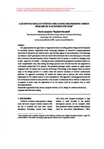
Fig. 1. AR location system: a set of ultrasound beacons emit a sequence of acoustic signals and the impinged remote location sensors send back RF signals to the radio base CPU, where a fast algorithm computes the position of the sensors and the position/orientation of the glasses frame.
For each RSj, the following four sphere equations that describe the distances between its microphone and the four tweeters forming the reference frame can be written:
(2)
(1)
where los is the constant offset introduced by the system components.
where a and b are the lateral dimensions of the reference frame (see Fig. 1). Resolving the four possible systems resulting from picking in all combinations only three equations at a time from the available four sphere equations of (2), four values for the location of the RS are determined: (x1, y1, z1), (x2, y2, z2), (x3, y3, z3) and (x4, y4, z4). It should be noted that each system of three equations of (2) has two possible solutions, and a single solution is obtained by limiting to the half-space in front of the reference frame the valid region of operation for the remote devices. If the estimated distances between the microphone and the four beacons would agree, four identical values for the RS location would be obtained. However, due to different disturbances (distance quantization, noise, spurious echoes, multipath, etc), l1j, l2j, l3j, l4j are
We can compute the distance lij by measuring the TOF between the emission of the acoustic pulse at Bi and the reception of the wavefront at RSj, for the moment assuming to know the speed of sound vij along that path, for example assuming that v is constant with time and the same in all the space region of interest (vij = v ∀i, j). At each signal transmitted by the beacon Bi, a corresponding array Di is filled with the computed lik (k = 1, 2,…Li), which are naturally ordered by increasing values. In absence of disturbances (for example, undesired acoustic reflections on walls, furniture, persons, floor or ceiling), the number of received RF signals is
442
2013 Joint UFFC, EFTF and PFM Symposium
generally affected by slight uncertainties. By computing the position of the given RS as the mean value of the four locations calculated on each one of the three axes, the error occurred in calculating the position of the RS can be reduced.
microphones, from 20 kHz up to 48 kHz, while the sampling frequency was set at 192 kSample/s. At said sampling frequency and assuming the sound speed 343 m/s, each sample represents a space interval of about 1.8 mm, which actually is the upper bound of the range estimation accuracy of the system. The chirp signal emitted by the beacons is composed of 1024 samples @192 kSample/s. The components of the prototype (see Figure 2) are listed below:
Furthermore, the developed algorithm incorporates a technique for discarding any invalid distance estimate, which could bring to a failure in the location of the RSs. For this purpose, the Euclidean distance between all the four computed RS positions is calculated, i.e. the square root of the sum of squared differences between every pair of two from the four computed RS coordinates:
CPU and Beacons: - PC: it is employed as processing unit of the system. Algorithms written in MATLAB (The MathWorksTM, Natick, MA, USA) are executed on the PC in order to build the acoustic pulses that are emitted by the transducers, and to acquire, store and analyze the return signals received from the remote sensors. - Data transmission/acquisition board: MOTU 828 mk3 (MOTU, Cambridge, MA, USA). This board provides ten analog inputs and ten analog outputs that can operate at a sample rate up to 192 kSample/s. However, the prototype uses only four outputs and one input. The connection with the PC is realized via FireWire Bus. The noticeable feature of the MOTU board is the capability to maintain sample-level synchronicity between emitted and recorded sequences, which is critical for correct TOF measurements. - Ultrasound emitters: Series 7000 Electrostatic Transducer (SensComp Inc., Livonia, MI, USA). Preliminarily performed tests have shown that this specific model is able to emit sufficiently accurate chirp signals in the desired ultra-acoustic band. The transducer also has a reasonable low cost for massproduction. However, as a drawback, the electrostatic technology requires to be polarized at high voltage and driven by signals with comparable voltage level. For these reasons, the electrostatic transducers must be supplied with a specific additional transformer circuitry. - Power output amplifier and polarization box: it hosts a four channels power amplifier board and a polarization board driving the electrostatic transducers. The four signal voltage elevators are realized using miniaturized 1:100 coil transformers LPR6235-752S (Coilcraft, Glasgow, UK), while a 200 V DC polarization voltage is obtained employing one ultra-miniature DC to HV DC Converter Q02-5-R (EMCO High Voltage Corporation, Sutter Creek, CA, USA) for all the four output channels. - RF receiver: it is realized using the RX section of the transceiver RTX MID 3V (Aurel S.p.A. Modigliana, FC, Italy), working at 433.92 MHz, according to the adopted ASK modulation scheme.
(3)
If the parameter Test results higher than a set threshold value, the location of the given RS should be considered as invalid and it is discarded. Thanks to the high locating rate achieved by the proposed system that will be discussed in the Section III, the occasional loss of locating data can be neglected in most applications. Unfortunately, due to the system structure and to the sequence of the operations above described, it is impossible to identify each remote device RSj and its corresponding distances (l1j, l2j, l3j, l4j) within the reception arrays (D1, D2, D3, D4). In fact, they are mixed together with the lijs belonging to the other sensors in the insonified field according to the position of the RSs, and a suitable search algorithm to pick up the right (l1j, l2j, l3j, l4j) has been then developed [8]. Using the geometrical constraints on the relative position of the located RSs, which has known are fixed in specific positions on the glasses frame, it is possible to further recognize the valid locations. III.
SETUP AND EXPERIMENTAL RESULTS
A prototype has been built with the aim to demonstrate the effectiveness of the proposed localization system for AR. The distances lij are estimated using coded ultrasound with good autocorrelation property, and moving the majority of the computations from the remote sensors to the CPU. This is obtained by transmitting back to the CPU a modified version of the ultrasound signals through the return channel. Thanks to the well-peaked shape of the autocorrelation, the detection of the arrival time could be easily carried out by the CPU even in case of strongly corrupted return signals. In particular, we employed as coded ultrasound signal the up-chirp (2048 kHz), while a “modified binary chirp” is sent through the return channel. The “modified binary chirp” is a binary signal derived from the original chirp signal by replacing each zerocrossing transition from low to high of the signal with a short pulse. The obtained modified binary chirp also shows a very sharp autocorrelation peak. In order to use commercial components and reduce the mass-production costs, the chirp frequency bandwidth has been chosen just beyond the upper corner of the working bandwidth of commercial high quality
Remote sensors: - Miniature microphone: the FG-6163 (Knowles Acoustics, Itasca, Illinois, USA) is a micromachined condenser microphone in a cylindrical shape package, length and diameter 2.6 mm, acoustical receiver window diameter 0.79 mm, and weight 80 mg. The choice of a very small microphone comes as a need of the intended applications. In fact, the remote sensors, as a whole, must be sufficiently small
443
2013 Joint UFFC, EFTF and PFM Symposium
and lightweight to avoid any discomfort, especially in the case of people location. Moreover, the receiving acoustical window, small in respect of the used wavelength range (7.117.1 mm in the 20-48 kHz range, with sound speed in air 343 m/s), ensures a good approximation of a point-like omnidirectional receiver.
IV. CONCLUSIONS The proposed system showed a positioning and trajectory tracking accuracy good enough for AR applications. Coded ultrasound provides high TOF measurement accuracy and robustness against disturbances. Very promising applications of the proposed localization method are in the field of AR, sport and military training, entertainment, and gaming interfaces. REFERENCES [1]
[2]
[3]
[4]
[5]
Fig. 2. Photo of the experimental setup, including the glasses frame equipped with four microphones, the TX and RX circuitries, the four ultrasound emitters, the audio board, the power amplifier box, and the CPU.
[6]
- Low-power microphone signal conditioning circuitry: it includes pre-amplification and amplification stages, a 20-48 kHz band-pass filter, and a Schmitt trigger in order to square the received signal and to drive the TX section of the transceiver RTX MID 3V (Aurel S.p.A. Modigliana, FC, Italy), working at 433.92 MHz. - The power supply of the remote sensor circuitry is a standard button type 3V lithium battery CR2032.
[7] [8]
F. Aldawi, A. P. Longstaff, S. Fletcher, P. Mather and A. Myers, “A high accuracy ultrasound distance measurement system using binary frequency shift-keyed signal and phase detection,” Proc. Computing and Engineering Annual Researchers' Conference 2007, University of Huddersfield, Huddersfield, pp. 1-7, 2007. A. Hernández, J. Ureña, J.J. García, M. Mazo, D. Hernanz, J. Dérutin, and J. Sérot, “Ultrasonic ranging sensor using simultaneous emissions from different transducers,” IEEE Trans. Ultrason., Ferroelect., Freq. Contr., vol. 51, n. 2, pp. 1660-1670, Dec. 2004. A. Smith, H. Balakrishnan, M. Goraczko and N. Priyantha, “Tracking Moving Devices with the Cricket Location System,” Proceedings of 2nd USENIX/ACM MOBISYS Conference, Boston, MA, June 2004. R. Ionescu, R. Carotenuto, F. Urbani, “3D localization and tracking of objects using miniature microphones,” Wireless Sensor Network, vol. 3, pp. 147-157, 2011. R. Carotenuto, Ionescu R., Tripodi P., Urbani F., "Three Dimensional Gestural Interface", 2009 IEEE Ultrasonics Symp, vol. 1, pp. 690-693, 2009. R. Carotenuto, “Localization of Sensor Networks using Ultrasounds and Radio Frequency,” Sensors and Microsystems: Proc. of AISEM 2008, Roma, Italy, Feb. 19‑21, World Scientific, pp. 435-439, 2008. R. Carotenuto, Tripodi, "Touchless 3D gestural interface using coded ultrasounds", 2012 IEEE Ultrasonics Symp, vol. 1, pp 146-149, 2012. R. Carotenuto, “A Method for Localizing Remote Devices using Acoustical and Electromagnetic Waves”, International Patent PCT WO2008065691 - 2008-06-05, European Patent 2095151- 2009-09-02, and US8089827 (B2) - 2012-01-03.
The realized prototype of the remote sensor, including miniaturized capacitive microphone, signal conditioning, signal squaring circuitry and TX transmission section is shown in Fig. 2. In particular, the realized prototype, in order to minimize the hardware, has only one TX section, driven by the logical OR of the squared binary outputs coming from the four microphones circuitries. During each localization time frame, the four emitters emit in sequence the same linear upchirp from 20 to 48 kHz, at predefined time intervals. The ultrasound signals received by the remote sensors are amplified, squared and modified in order to transmit back to the CPU the low-to-high transitions only. The signals received by the RX are recorded by the acquisition board and then processed with a suitable MATLAB code on the PC. The time listening window was set to 1500 samples, whose duration is 7.8 ms @ 192 kSamples/s recording rate, or equivalent to a range of about 0.9 meters, assuming the speed of sound in air 343 m/s. The prototype showed locating accuracy of about 4 mm in all directions within a range of 150 cm from the emitters, and a refresh rate of 20 Hz, with the location and display MATLAB codes running on a standard PC notebook.
444
2013 Joint UFFC, EFTF and PFM Symposium