Second, a frequency-domain based registration algorithm ... main components, the acquisition, the registration and ..... best point of view to image the scene. 7.
2009 Canadian Conference on Computer and Robot Vision
3D Modeling from Multiple Views with Integrated Registration and Data Fusion Alain Boyer, Phillip Curtis and Pierre Payeur School of Information Technology and Engineering University of Ottawa, Ontario, Canada {aboye074, pcurtis, ppayeur}@site.uottawa.ca registration component estimates the transformation between the multiple views. The data fusion procedure merges the respective data sets and estimates the surface over the set of objects. Most current systems require that the registration component be highly coupled to the acquisition component. For instance, the classical turntable approach [1], [2], [3], [4] requires calibration and synchronization between the acquisition and the rotating devices. It also usually puts a limit on the size of objects that can fit on the turntable. In order to create a flexible modeling system that is operational with minimal constraints on its motion, a reduction of the coupling between the acquisition and the registration is necessary. This implies that all components must be selected and designed so that they operate independently. As a result, the position of the acquisition system with respect to the objects being imaged should remain flexible. This way, multiple measurements can be collected on the scene or objects by freely moving the acquisition platform. The cost of the system is mainly influenced by the technology used in the acquisition stage. In order to keep this cost low, laser scanners are not considered here and a camera-based system is selected. Most vision-based and passive acquisition techniques rely on shape from silhouette [1], [5]. The disadvantages with these approaches are the difficulties of background segmentation and, more importantly, the need for the calibration between views to be known a priori, which conflicts with the notion of low coupling between the acquisition and registration components. An active vision technology is therefore preferred in order to directly acquire a depth map of the scene from each viewpoint. Using the structured light technique introduced by Desjardins et al. [6], a precise and dense 3D map can be achieved on featureless objects. As for the registration, the objective is to eliminate the need for initially estimating the movement of the acquisition device between views. Registration
Abstract This paper presents an integrated modeling system capable of generating coloured three dimensional representations of a scene observed from multiple viewpoints. Emphasis is given to the integration of the components and to the algorithms used for acquisition, registration and final surface mapping. First, a sensor operating with structured light is used to acquire 3D and colour data of a scene from multiple views. Second, a frequency-domain based registration algorithm computes the transformation between pairs of views from the raw measurements and without a priori knowledge on the transformation parameters. Finally, the registered views are merged together and refined to create a rich 3D model of the objects. Real world modeling examples are presented and analyzed to validate the operation of the proposed integrated modeling system.
1. Introduction Scene reconstruction is the process of generating a 3D model of an object or a scene. This model can be used for various applications such as measurement, mapping, recognition, obstacle avoidance or augmented reality. Much literature has dealt with the object reconstruction problem; however, many constraints still remain on the objects being imaged as well as on the surrounding environment. The goal of this work is to develop a low cost scene reconstruction system to be used in robotic exploration of unknown environments. The accuracy and precision of the models are secondary to the flexibility, ease of use and robustness of the sensor, since the primary motivation is to interpret and map the environment. Such a modeling system usually consists of three main components, the acquisition, the registration and the data fusion parts. The acquisition stage takes care of acquiring multiple 3D maps of the scene, while the 978-0-7695-3651-4/09 $25.00 © 2009 IEEE DOI 10.1109/CRV.2009.39
252
In section 2, the proposed integrated framework for scene reconstruction is presented. The selected acquisition, registration and data fusion components are detailed in sections 3, 4 and 5 respectively. Experimental results are analyzed in section 6 to validate the technique.
parameter estimates should come entirely from the actual 3D maps, provided that there is adequate overlap between them. Two lines of thought exist on how to solve this problem. The first one is to extract some features that are common between the two different views, and match them [7], [8]. Most of the complexity in this solution comes from determining specific features and validating their respective matches. The second approach is to align 3D data sets without any analysis of the structure of their content, which can be achieved with the iterative closest point (ICP) algorithm of Besl and McKay [9]. ICP works very well in general, but the technique requires the data to be closely aligned from the beginning in order to avoid convergence to a local minimum solution. In the proposed framework, an original approach introduced by Curtis et al. [10] is considered. This method, which was inspired by Lucchese et al. [11], relies on using a frequency domain transformation to decouple the estimation of the rotation from that of translation to generate first estimates of the registration parameters. The ICP algorithm can then efficiently refine these estimates regardless of the sensor’s viewpoints. Finally, in order to produce a model of the scene, a surface map can be extracted from the unorganized point cloud that results from the acquisition and registration steps. This surface is easy to interpret programmatically by a navigating robotic platform and visually accurate for a human operator to recognize important features. There is extensive research in this field [12], [13], [14] and the development of surface maps remains beyond the scope of the current work. Here, the algebraic point set surface method [15] is applied to the resulting point cloud to simplify and merge the modeling results.
2. Proposed Integrated Framework The proposed framework combines original solutions for acquisition, registration and data fusion to produce an integrated 3D modeling system that can be used to estimate the shape and colour of a scene from multiple views with minimal intervention from the operator. Fig. 1 illustrates the interconnections of the three main components and the flow of data between them. The acquisition module, based on structured light stereoscopic imaging, successively acquires several views of the scene before it. Depending on the dimension of the subject under analysis, the object imaged or the sensor itself is translated and rotated to capture multiple views. Images are acquired with structured light before being processed to extract colour coded feature points on which triangulation is performed. Each initial view generates an independent 3D point cloud relative to the corresponding pose of the sensor. These point clouds are transferred to the registration module where they are first mapped as voxel clouds and then converted to the frequency domain. The registration procedure estimates the rotation and translation parameters that represent the relative displacement of the sensor between successive views.
Figure 1. Interconnection of acquisition, registration and data fusion modules. A number, n, of point clouds (PC) are acquired and converted to voxel clouds (VC) and then to the Fourier (F) domain. The translation (T) and rotation (R) between the n-1 pairs of views are estimated and the point clouds are merged to generate the global 3D model.
253
of every 3x3 group of coloured regions facilitates feature extraction, provides higher robustness to the inherent colours present in the scene, and increases the confidence on matches between the artificially created feature points. In this case, a palette of three colours (red, green, blue) is selected, which is robust to a wide range of object surface characteristics and ambient lighting levels. At the beginning of the acquisition phase, a pair of left and right images is acquired without the projection of structured light to secure the original colour of the objects. The offline generated PR pattern is then projected on the objects and a second pair of images is captured. In order to increase the resolution of the 3D model, marching patterns are also used. That is, the same PR pattern is successively shifted horizontally and vertically while subsequent pairs of images are acquired. This strategy significantly increases the number of matched feature points created by the extra locations of the projected pattern on the surface of the scene, and therefore increases the density of points in the 3D point cloud. Every pair of stereoscopic images is processed to extract the location of the colour coded feature points. The coloured regions are first extracted by segmentation with a histogram analysis that highlights the dominant colours in the images. Those regions are labelled, their centroid is computed and a statistical analysis is performed to eliminate false detections and further segment larger blobs associated with two or more adjacent coloured regions. Such regions can appear as a merged cluster due to different orientations of the object’s surface under the projected pattern. Uniquely defined 3x3 colour codes are recovered and a confidence measure is computed for each one, in relation with the original known projected colour map. Codes with a low confidence are dropped, while similar valid codes between the left and right images are matched to define feature points for the reconstruction phase.
Finally, the data fusion aligns the respective point clouds using the previously estimated registration parameters and merges them into a single large set of 3D coordinate measurements. A surface map is also generated to produce a complete and realistic 3D model of the scene. Using these components, the modeling system adapts and scales to its environment. The resulting system is flexible since it is possible to image small objects or large scenes, as well as increase or decrease the density of the acquired range data. Moreover, the system can generate visually pleasing 3D coloured surface models when necessary or simply output fused point clouds when used in the context of autonomous robot exploration.
3. Acquisition of 3D Points The acquisition module is an independent system capable of producing 3D point clouds of objects before it. The sensor, introduced in the work of Desjardins et al. [6], uses active vision in the form of structured light to achieve a dense stereoscopic acquisition and reconstruction of the shape and colour of surfaces. The physical setup of the 3D sensor is composed of two colour cameras and one LCD projector. The cameras are rigidly assembled as a stereo pair on a bracket above the projector as shown in Fig. 2a. Only the stereo rig requires calibration of its intrinsic and extrinsic parameters. The projector is used to project colour coded patterns onto the scene but is not calibrated with respect to the cameras. This provides maximum flexibility for the device to be moved, focused or adjusted in accordance with the depth or brightness of the scene so that the projected pattern appears sharp and in focus. To achieve a dense 3D reconstruction on objects that exhibit few features, a bi-dimensional pseudorandom (PR) array of coloured squares is projected on the scene, as shown in Fig. 2b-c. The unique encoding
(a)
(b)
(c)
Figure 2. (a) Stereoscopic structured light acquisition system, (b) bi-dimensional pseudo-random pattern, and (c) its projection onto an inkjet printer.
254
(a)
(b)
(c)
Figure 3. (a) Colour image of a printer, (b) 3D point cloud reconstruction from a single view (colour omitted), and (c) same point cloud augmented with its actual coloured point set surface.
scenes. The primary advantage of the frequency domain approach is that it inherently decouples the estimation of the rotation from that of the translation. First, a voxelized representation of the point cloud is created for each viewpoint because the Fourier transform requires the use of a regularized data G G representation. If Im1 [n ] and Im 2 [n ] are voxelized range data sets collected on the same object, but differing in their viewpoint by a rotation R and a G translation T, with n being the space domain location index vector, then by definition: G G Im1 [n ] = Im 2 [Rn + T ] (1)
In order to minimize the occurrence of outliers, the list of feature points is further refined with a RANSAC algorithm. The optimal polynomial reconstruction algorithm [16] that validates the epipolar constraint is then used to estimate the actual 3D coordinates of every point. To validate the operation of the acquisition and modeling stage, experiments were conducted on several objects measured from a single viewpoint. Fig. 3 demonstrates the accuracy of the point cloud produced by the acquisition system on the upper part of a standard printer that was scanned from a single viewpoint using 36 shifted patterns. A dense and uniformly distributed map of the printer surface is reconstructed with an average resolution of 1.5mm. Due to the spatial distribution of the PR codes used for the structured light, it remains difficult to acquire measurements on regions with sharp edges, as shown in Fig. 3b. This happens because the 3x3 coloured regions are skewed, which precludes local recognition of feature points. But this limitation is largely overcome with the addition of extra views to the model. Moreover, an accurate colour measure, estimated from the average of the original left and right source images, is mapped on every reconstructed point, producing a rich dataset as can be seen in Fig. 3c. Details on the colour mapping increase along with the resolution of the scan using the marching pattern described above. Such accurate coloured 3D models are not available with most conventional stereo vision systems or laser scanners.
The Fourier transform of eq. (1) is computed with G k as the frequency index, M as a dimensional scale factor, and FIm1 and FIm2 as the frequency domain G G representations of Im1 [n ] and Im 2 [n ] respectively. The transformations result in:
[ ]
[]
GT G G FIm2 Rk = FIm1 k e − j 2π (Rk ) MT
(2)
By considering respectively the amplitude and phase components of eq. (2), the estimation of rotation, eq. (3), and translation, eq. (4), can effectively be decoupled: G G FIm2 Rk = FIm1 k (3)
[ ]
[ ]
[]
[]
G G GT ∠FIm2 Rk = ∠FIm1 k − 2π Rk MT
4. Registration between Multiple Views
( )
(4)
Using the knowledge that the rotation can be estimated without knowing the translational differences between the views, it can be observed that for any rotation about an arbitrary axis, the points that lie on this axis do not change in space. Therefore, taking the absolute difference between the respective magnitude frequency domain images, the axis of rotation is identified by searching for the line of minimal energy
In order to perform registration between the point clouds obtained from each viewpoint, without a priori estimates of the rotation and translation parameters between the views, the frequency domain registration technique introduced by Curtis et al. [10] is used. This ensures a maximum of flexibility for the displacement of the sensor in order to map the surface of complex 255
If the application requires details or a higher level of processing such as mapping and feature detection in a robotic context, the entire raw point cloud can be sent to the next processing stage. On the other hand, if the goal is to produce a visually pleasing model of the scene that is easy to interpret, the point cloud is transformed into a surface. Because of the overlap between the successive viewpoints, the concatenated point cloud results in oversampled and densely populated regions. To construct visually accurate models, locally redundant points are removed before a surface mesh is generated as redundant points do not positively contribute to the visual appearance of the model. First, the global point cloud is voxelized and decimated by keeping only one point in each voxel as a representative entity for that voxel. Not only does this remove redundant points, it also greatly reduces the size of the point cloud, which in turn speeds up the processing of all subsequent steps. Next, a surface is extracted from the unorganized point cloud using the point set surface technique that stems from point-based graphics research. Points that are near a local section of the point cloud are projected onto a moving least squares (MLS) [13] surface that approximates the point cloud locally [14]. This allows the extraction of a surface in the presence of noise or error due to the registration procedure. The advantage of using the algebraic point set surface (APSS) [15] variant of the algorithm is that points are fitted to an algebraic surface, in this case an algebraic sphere, rather than a simple plane. This improves the final model in areas of high curvature and regions where the point cloud is undersampled. Once the MLS surface is defined, a coarse mesh is extracted using the marching cubes algorithm [17]. The latter voxelizes the MLS surface and determines how the surface intersects with the voxels. Using a case table, the triangle topology of each voxel is determined and a triangular mesh is constructed. Finally, the mesh is further refined using another, more accurate, projection back onto the MLS surface. All of the operations regarding the surface extraction in this section are performed on the global point cloud obtained after registration using Meshlab [18].
that passes through the origin (DC point). This is achieved by using a neighbourhood path searching algorithm, where the minimal energy path away from the origin and towards the edge of the difference 3D frequency image is followed. Once the axis of rotation is known, the angle of rotation is determined by selecting a small subset of the 3D frequency points, iterating for different rotations about the axis of rotation, and choosing the angle of rotation that produces the minimal sum of absolute difference. However, there exists a Hermitian symmetry in the frequency domain (ω → 2π − ω ) , so there are two possible solutions for the rotation angle. Fortunately, the estimation of the translation parameter solves this discrepancy. The estimation of translation is performed by first G rotating Im 2 [n ] by each of the possible solutions, and then projecting the respective points onto the three cardinal axes. These projections are cross-correlated G with the projections performed on Im1 [n ] . The estimation of the translation corresponds to the lag of the maximum peak of the respective cross correlations. The correct solution corresponds to the solution set where the peak in the cross correlation is highest and has the lowest noise energy. From the initial estimates found using the above technique, the rotation and translation parameters can finally be refined using the ICP algorithm for higher accuracy.
5. Data Fusion and Surface Estimation The data fusion component is the last stage in the proposed modeling framework. It takes the outputs of both the acquisition and registration modules and merges the data sets obtained from the respective viewpoints into a 3D model of the objects in the scene. The registration component determines the transformation between successive views. In order to merge all views together, each one must first be expressed with respect to a common reference frame. The initial view is selected as the common reference. Therefore, the respective transformations between the latter and all other views are computed and applied to their respective point clouds, ensuring a consistent base for the 3D representations. Finally, all of the point clouds are merged by concatenating the list of points to produce a single large point cloud modeling all objects in the scene with respect to the first location and orientation of the structured light imaging system.
6. Experimental Evaluation The integrated 3D modeling system was tested with multiple objects and scenes to evaluate its performance and flexibility. The results of two modeling tests are presented here.
256
(a)
(b)
(c)
(d)
(e)
(f)
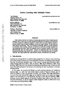
Figure 4. Modeling of a printer: (a) colour image of the object, (b) textured point set surface map for a single view at 70°, and (c) at 220°. Global point set surface model from the merge of 36 local data sets: (d) front view, (e) rear view, and (f) zoomed view of the rear label.
The first case consists of a small object that allows the construction of a closed surface map. An inkjet printer, shown in Fig. 4a, was imaged from 36 different points of views, separated by roughly 10°, to ensure full 360° coverage. The structured light pattern was shifted 36 times and point clouds of about 30000 points with 1.5mm resolution were produced for each view. Local models obtained from two separate views are shown in Fig. 4b-c. The registration was performed on a 256x256x256 voxelization of the data and the final model surface was extracted using an MLS filter scale of 7mm. The results shown in Fig. 4d-f demonstrate that it is possible to produce an accurate model of relatively small objects despite the limited accuracy of the acquisition system along edges. The shape of the printer is clearly visible and fully textured. Such a model can be readily used for mapping, obstacle avoidance, or objects recognition applications. The second scenario exemplifies the capability of the proposed imaging system to model a large and complex scene, in a general context, where the sensor cannot be moved as easily to capture measurements from all faces. In the present case, shown in Fig. 5a, a robotic workcell of approximately 1.5m3 is explored with a mobile version of the integrated imaging system. The scene was imaged from 12 separate
viewpoints, starting perpendicular to the computer monitor and moving left along an arc by about 25 to 50cm between each view and changing the orientation to keep the scene within the field of view of the 3D sensor. In this test, the structured light pattern was shifted 9 times, resulting in point clouds of approximately 4000 points with 5mm resolution for each view. The same parameters for the registration and surface extraction operations as above were used. In spite of the complexity of the scene, its unconstrained geometry, the different colours and reflectance characteristics of the objects, no adjustments were required on the lighting and operation of the sensor to collect and register the 3D measurements. The model of the robot workcell scene shown in Fig. 5b-d demonstrates that the system is capable of imaging a real environment with multiple objects of varying colour and unconstrained placement. This scene is particularly interesting since the track of the manipulator robot is occluded in the first views but correctly appears behind the monitor as the sensor is moved along the arc. However, occlusions due to objects near the sensor can contribute to apparent holes in the surface model. For example, the chair is directly responsible for the missing bottom corner of the monitor shown in Fig. 5d.
257
(a)
(b)
(c)
(d)
Figure 5. Modeling of a robotic workcell: (a) colour image of the scene, and global coloured point set surface model of the scene from (b) a zoomed in view, (c) a front view, and (d) a lateral view.
sensor is mounted atop an autonomous robotic platform that is mapping an environment, as the platform has some flexibility when selecting its next best point of view to image the scene.
A set of surface patches, which can be seen from the sensor's point of view, are merged to create a partial map of the content of this environment. The horizontal surfaces of the table and bench do not appear in the reconstructed model because the mobile sensor was only imaging horizontally, as is typical with a mobile robot and a vision sensor exploring an unknown world. To further reduce the amount of holes in the model and detect horizontal surfaces, range data can be acquired from more viewpoints at varying elevations. Nevertheless, the resulting model is accurate enough to further drive a robotic exploration toward specific objects on which higher accuracy or completeness is required, while the colour mapped onto the model makes the recognition of objects straightforward for an operator supervising the operation of the mobile platform. Based on this experiment, a 75% overlap between successive views is preferable for high quality registration. However, at the time of acquisition, only a visual check of the overlap is necessary and the acquisition component can be moved arbitrarily about the scene. The overlap constraints mainly determine the number of views required to achieve a given level of completeness in the model. The registration technique is robust enough to accommodate for various patterns of movement between views. These characteristics become very useful when the range
7. Conclusion This paper proposes an integrated 3D modeling system capable of imaging closed objects as well as larger real world scenes from an affordable imaging technology and efficient registration mechanism. The system builds upon a structured light sensor that offers robustness to various reflectance characteristics and lighting levels in the scene. It captures range data of high density and detects featureless objects as opposed to standard stereo systems. A generic frequency domain registration approach that does not require an initial estimate of the transformation parameters between viewpoints is used to provide an optimal data fusion operation while preserving the necessary freedom on the sensor’s positioning. All components are minimally coupled to ensure that the system is easy to operate, flexible, and adapts to scenes of various sizes, complexity and colours. The results demonstrate that the modeling system has a variable depth of field and scales well from small objects to large scenes, which is not possible with laser systems.
258
The proposed modeling technology is designed using a pragmatic approach with autonomous robotic exploration under human supervision in mind. Multiple views of the environment can be merged without the need of accurately tracking the mobile platform’s movements. The generated surface models exhibit accurate shape reconstruction and contain rich colour and texture information. Finally, the results are suitable for modeling, mapping, obstacle avoidance, and object recognition where very high precision is not essential.
[7]
[8]
[9]
8. Acknowledgments [10]
The authors wish to acknowledge the financial support from the Ontario Centre of Excellence for Communications and Information Technology, and the collaboration of Neptec Design Group to this research work.
[11]
9. References [1]
[2]
[3] [4]
[5]
[6]
[12]
J. Arnabat, S. Casanovas, and G. Medioni, “3D Modeling from Turntable Sequences using Dense Stereo Carving and Multi-view Consistency”, Proceedings of the 17th International Conference on Pattern Recognition, vol. 4, Cambridge, UK, 2004, pp. 36-39. W.K. Leow, Z. Huang, Y. Zhang, and R. Setiono, “Rapid 3D Model Acquisition from Images of Small Objects”, Proceedings of Geometric Modeling and Processing, Hong Kong, 2000, pp. 33-41. H.Y. Lin, and M. Subbarao, “Vision System for Fast 3D Model Reconstruction”, Optical Engineering, 43(7), SPIE, 2004, pp. 1651-1664. S.Y. Park, and M. Subbarao, “A Multiview 3D Modeling System Based on Stereo Vision Techniques”, Machine Vision and Applications, 16(3), Springer, Heidelberg, 2005, pp. 148-156. Y. Yemez, and F. Schmitt, “3D Reconstruction of Real Objects with High Resolution Shape and Texture”, Image and Vision Computing, 22(13), Elsevier, 2004, pp. 1137-1153. D. Desjardins, and P. Payeur, “Dense Stereo Range Imaging with Marching Pseudo-Random Patterns”, Proceedings of the Canadian Conference on Computer and Robot Vision, Montreal, QC, 2007, pp. 216-223.
[13]
[14]
[15]
[16] [17]
[18]
259
C.S. Chen, Y.P. Hung, and J.B. Cheng, “A Fast Automatic Method for Registration of PartiallyOverlapping Range Images”, Proceedings of the 6th International Conference on Computer Vision, Bombay, India, 1998, pp. 242-248. E. Gagnon, J.F. Rivest, M. Greenspan, and N. Burtnyk, “A Computer-Assisted Range Image Registration System for Nuclear Waste Cleanup”, IEEE Transactions on Instrumentation and Measurement, 48(3), 1999, pp. 758-762. P.J. Besl, and H.D. McKay, “A Method for Registration of 3-D Shapes”, IEEE Transactions on Pattern Analysis and Machine Intelligence, 14(2), 1992, pp. 239-256. P. Curtis, and P. Payeur, “A Frequency Domain Approach to Registration Estimation in 3-D Space”, IEEE Transactions on Instrumentation and Measurement, 57(1), 2008, pp. 110-120. L. Lucchese, G. Doretto, and G.M. Cortelazzo, “A Frequency Domain Technique for Range Data Registration”, IEEE Transactions on Pattern Analysis and Machine Intelligence, 24(11), 2002, pp. 14681484. H. Hoppe, T. DeRose, T. Duchamp, J. McDonald, and W. Stuetzle, “Surface Reconstruction from Unorganized Points”, Proceedings of the 19th Annual Conference on Computer Graphics and Interactive Techniques, Chicago, IL, 1992, pp. 71-78. D. Levin, “Mesh-Independent Surface Interpolation”, G. Brunnett, B. Hamann, H. Müller, L. Linsen (eds.), Geometric Modeling for Scientific Visualization, Springer, 2004, pp. 37-49. M. Alexa, J. Behr, D. Cohen-Or, S. Fleishman, D. Levin, and C.T. Silva, “Computing and Rendering Point Set Surfaces”, IEEE Transactions on Visualization and Computer Graphics, 9(1), 2003, pp. 3-15. G. Guennebaud, and M. Gross, “Algebraic Point Set Surfaces”, Proceedings of the International Conference on Computer Graphics and Interactive Techniques, San Diego, CA, 2007. R. Hartley, and A. Zisserman, Multiple View Geometry, Cambridge University Press, UK, 2003. W.E. Lorensen, and H.E. Cline, “Marching Cubes: A High Resolution 3D Surface Construction Algorithm”, Proceedings of the 14th Annual Conference on Computer Graphics and Interactive Techniques, New York, NY, 1987, pp. 163-169. Meshlab, [online], http://meshlab.sourceforge.net