Accepted Manuscript Title: 3D printing and modelling of customized implants and surgical guides for non-human primates Author: Xing Chen Jessy K. Possel Catherine Wacongne Anne F. van Ham P. Christiaan Klink Pieter R. Roelfsema PII: DOI: Reference:
S0165-0270(17)30132-2 http://dx.doi.org/doi:10.1016/j.jneumeth.2017.05.013 NSM 7739
To appear in:
Journal of Neuroscience Methods
Received date: Revised date: Accepted date:
9-3-2017 5-5-2017 8-5-2017
Please cite this article as: Chen X, Possel JK, Wacongne C, van Ham AF, Klink PC, Roelfsema PR, 3D printing and modelling of customized implants and surgical guides for non-human primates, Journal of Neuroscience Methods (2017), http://dx.doi.org/10.1016/j.jneumeth.2017.05.013 This is a PDF file of an unedited manuscript that has been accepted for publication. As a service to our customers we are providing this early version of the manuscript. The manuscript will undergo copyediting, typesetting, and review of the resulting proof before it is published in its final form. Please note that during the production process errors may be discovered which could affect the content, and all legal disclaimers that apply to the journal pertain.
1
3D printing and modelling of customized implants and
2
surgical guides for non-human primates
Xing Chen1, Jessy K. Possel1, Catherine Wacongne1, Anne F. van Ham1, P.
7
Christiaan Klink1,2,3,4 & Pieter R. Roelfsema1,3,4
ip t
3 4 5 6
1
12
Meibergdreef 47, 1105 BA, Amsterdam, Netherlands
13
2
14
Neuroscience, Meibergdreef 47, 1105 BA, Amsterdam, Netherlands
15
3
16
1081 HV, Amsterdam, Netherlands
17
4
18
Amsterdam, Netherlands
us
Department of Vision & Cognition, Netherlands Institute for Neuroscience,
M
Department of Integrative Neurophysiology, VU University, De Boelelaan 1085,
d
Department of Psychiatry, Academic Medical Center, Postbus 22660, 1100 DD,
Ac ce pt e
21
an
Department of Neuromodulation & Behaviour, Netherlands Institute for
19 20
cr
8 9 10 11
Type of article: Research article
22
Corresponding author:
23
X. Chen. Postal address: Netherlands Institute for Neuroscience, Meibergdreef
24
47, 1105BA, Amsterdam, Netherlands
25
Email:
[email protected] Phone: +31(0)20 5664581 Fax: +31(0)20 5666121
1
Page 1 of 53
26 27 28 29
Abstract Background: Primate neurobiologists use chronically implanted devices such as
30
pedestals for head stabilization and chambers to gain access to the brain and
31
study its activity. Such implants are skull-mounted, and made from a hard,
32
durable material, such as titanium.
ip t
33
New method: Here we present a low-cost method of creating customized 3D-
35
printed cranial implants that are tailored to the anatomy of individual animals.
36
We performed pre-surgical computed tomography (CT) and magnetic resonance
37
(MR) scans to generate three-dimensional (3D) models of the skull and brain. We
38
then used 3D modeling software to design implantable head posts, chambers,
39
and a pedestal anchorage base, as well as craniotomy guides to aid us during
40
surgery. Prototypes were made from plastic or resin, while implants were 3D-
41
printed in titanium. The implants underwent post-processing and received a
42
coating of osteocompatible material to promote bone integration.
M
an
us
cr
34
43
Results: Their tailored fit greatly facilitated surgical implantation, and eliminated
45
the gap between the implant and the bone. To date, our implants remain robust
46
and well-integrated with the skull.
Ac ce pt e
47
d
44
48
Comparison with existing method(s): Commercial-off-the-shelf solutions
49
typically come with a uniform, flat base, preventing them from sitting flush
50
against the curved surface of the skull. This leaves gaps for fluid and tissue
51
ingress, increasing the risk of microbial infection and tissue inflammation, as
52
well as implant loss.
53 54
Conclusions: The use of 3D printing technology enabled us to quickly and
55
affordably create unique, complex designs, avoiding the constraints levied by
56
traditional production methods, thereby boosting experimental success and
57
improving the wellbeing of the animals.
58 59
Keywords
2
Page 2 of 53
d
M
an
us
cr
ip t
3D printing, cranial implants, electrophysiology, primate
Ac ce pt e
60
3
Page 3 of 53
61
1. Introduction
63
Primate electrophysiologists use a range of implantable devices to access and
64
record from brain regions of interest. For electrode recordings in awake animals,
65
the subjects are often implanted with recording chambers, which protect the
66
brain from the external environment in between experiments (Evarts 1966;
67
Gardiner and Toth 1999; Adams et al. 2011). During recordings, researchers can
68
open up the chamber and insert electrodes directly into the brain, sampling
69
neuronal activity at various depths and spatial locations. For chronic
70
multicellular recordings, researchers may choose to implant electrode arrays
71
containing dozens of recording sites into the brain. These arrays are connected
72
to a skull-mounted pedestal via transcranial wires (Campbell et al. 1991;
73
Nordhausen et al. 1994; Nicolelis et al. 2003). An interface consisting of either
74
electrical contact points or a wireless transceiver unit is mounted on the
75
pedestal, providing a connection to external equipment. Furthermore, when
76
performing acute recordings, or when a task necessitates the spatial stabilization
77
of images on the retina, fixation of the head is commonly achieved using a single-
78
piece, screw-mounted head post (Adams et al. 2007), or an equivalent device
79
with multiple contact points on the skull (Pigarev et al. 1997; Isoda et al. 2005).
cr
us
an
M
d
Ac ce pt e
80
ip t
62
81
For each of these applications, the implant must remain firmly fixed to the skull
82
over extended periods of time. Poorly fitting implants may fail to integrate with
83
the bone, come loose, or break off, affecting the welfare of the animals and
84
disrupting experiments (Johnston et al. 2016). Here, we describe how new 3D
85
printing techniques can be used to ensure a seamless fit between the bone and
86
the implant, and to facilitate surgical implantation. We also describe the use of
87
3D modelling during pre-surgical planning to enhance the accuracy of electrode
88
insertion.
89 90
The technique of 3D printing refers to the process of using a machine to
91
additively assemble a 3D object layer by layer, using a digital design as a
4
Page 4 of 53
blueprint. This approach allows for highly customizable designs, which can be
93
printed in small quantities at affordable prices, due to the relatively low set up
94
costs and minimal wastage of material. Manufacturers can choose from a
95
growing range of materials, including plastics, metals, ceramics, and wood, with
96
various degrees of hardness, strength, durability, and elasticity. These methods
97
are hence gaining popularity for use in the laboratory. Recent applications of 3D
98
printing in neuroscience include 3D-printed models of neuronal cell types for
99
visualization of their morphology (McDougal and Shepherd 2015), as well as 3D-
100
printed lab equipment, such as micromanipulators (Patel et al. 2014; Baden et al.
101
2015) and cortical recording platforms, cranial windows, and perfusion
102
chambers for rodent experiments (Tek et al. 2008). To promote the sharing of
103
scientific 3D models, the National Institutes of Health recently launched the NIH
104
3D Print Exchange- a free and publicly accessible online repository for 3D-
105
printable models in the fields of biology and medicine (https://3dprint.nih.gov/).
106
Here, we focus on the use of 3D printing for the creation of customized cranial
107
implants in non-human primate (NHP) neurophysiology experiments.
cr
us
an
M
108
ip t
92
Typically, implants used in NHP neurobiology, such as head posts and chambers,
110
are one-size-fits-all solutions that can be purchased from companies such as
111
Crist Instrument Co., Inc (for a few hundred euros). These off-the-shelf implants
112
require time-consuming manual adjustments during each surgical procedure
113
(Adams et al. 2007; 2011; Mulliken et al. 2015), such as bending of the legs of the
114
implant with pliers or tapping them with a hammer. However, even if the legs
115
are pliable, a portion of the base is sometimes flat and rigid (as seen, for example,
116
in Figure 1A, or the head post designed by Adams et al. 2007), making it
117
impossible to obtain a curved surface. Even after bending of the legs, the fit
118
between the implant and the skull is often imperfect, making it harder for the
119
implant to integrate with the bone. Furthermore, the space between the metal
120
and the bone increases the risk of unwanted growth of granulation tissue in the
121
gap between the skull and the implant, which may contribute to infection and
122
inflammation, bone and skin degradation, implant instability, and even implant
123
failure (Galashan et al. 2011; Johnston et al. 2016; Raphel et al. 2016).
Ac ce pt e
d
109
124
5
Page 5 of 53
If a study involves functional imaging experiments, then metal implants typically
126
cannot be used as they interfere with the magnetic field in the scanner and
127
generate an artefact in the signal. Instead, the implants are generally made from
128
radiolucent material such as polyether ether ketone (PEEK) or polyetherimide
129
(PEI). As the technology for 3D printing with these MR-compatible materials is
130
still at an early stage of development, we here focus on 3D printing in titanium.
131
However, it is conceivable that 3D printing with MR-compatible materials will be
132
possible in the future.
ip t
125
134 135 136 137 138 139 140 141
Ac ce pt e
d
M
an
us
cr
133
Figure 1. A) One-size-fits-all head posts, such as the one pictured here, have legs that can be bent into the desired shape. However, the metal at the middle of the base (indicated by the red arrow) is relatively thick, and cannot be bent. B) The CerePortTM device consists of one or more electrode arrays that are implanted in the brain, which connect to a skull-mounted pedestal interface via a wire bundle (top). An electronic interface board connects the pedestal to the data acquisition and/or stimulation equipment during each recording session (bottom). The base of the pedestal is flat, leaving a gap between the base and the skull (indicated by the black arrow), or requiring thinning of the bone.
142 143
For electrophysiology that involves chronically recording from dozens of
144
neurons, the CerePortTM from Blackrock Microsystems (Salt Lake City, Utah) is a
145
popular tool in many primate neuroscience labs. Its FDA-approved, CE-marked
146
counterpart, the NeuroPortTM, is used in clinical trials with human patients
6
Page 6 of 53
(Collinger et al. 2013; Flesher et al. 2016). The CerePortTM pedestal provides a
148
percutaneous interface between the implanted multielectrode arrays and the
149
external data acquisition equipment (Figure 1B), via an electronic interface
150
board (EIB) that is screwed onto the upper half of the pedestal during each
151
experimental session. The base of the pedestal contains eight screw holes,
152
allowing it to be mounted on the skull. However, the diameter of the pedestal
153
base is small and it lacks legs, concentrating the screws over a limited surface
154
area. Furthermore, the base of the pedestal is flat and does not sit flush against
155
the skull, which may contribute to problems with infection and implant
156
detachment. One possible solution is to improve the attachment to the bone
157
using dental cement. However, in some animals, tissue builds up between the
158
bone and the cement with time, thus creating a space that is susceptible to
159
microbial infection. Another possible solution is to shave the bone down, in
160
order to create a flat surface. However, it is not easy to remove sufficient bone so
161
that the flat surface of the implant fits well, and in addition, this technique
162
reduces the thickness of the skull underneath the implant, which may create a
163
weak spot. Hence, we sought to create implants that provide a better fit with the
164
skull than these commercial-off-the-shelf solutions.
cr
us
an
M
d
Ac ce pt e
165
ip t
147
166
In previous studies, customized implants were designed using anatomical scans
167
of the individual animal’s skull, ensuring a good fit between the bone and the
168
implant, reducing the duration of surgery, and decreasing the likelihood of
169
granulation tissue growth and infection (McAndrew et al. 2012; Lanz et al. 2013).
170
These implants were typically manufactured using computer numerical control
171
(CNC) machines, which use traditional milling methods to ‘sculpt’ objects out of a
172
solid block of starting material, under the control of computer-aided design
173
(CAD) programmes. Several research labs carry out their design process and
174
production using CAD software and CNC machines, either in-house (Galashan et
175
al. 2011; Lanz et al. 2013; Mulliken et al. 2015) or outsourced to a CNC workshop
176
(Adams et al. 2007) or a company that specialises in such implants (Johnston et
177
al. 2016). Several companies offer CNC milling services to create customized
178
solutions for a small range of implantable products (e.g. Crist Instruments Co.,
7
Page 7 of 53
179
Inc, Hagerstown, MD; Gray Matter Research, Bozeman, MT; Rogue Research Inc.,
180
Montreal, Canada).
181 A drawback of these techniques is that they are costly, for several reasons: CNC
183
machines still rely on traditional techniques, such as drilling and sawing, to
184
generate the final product. The use of CNC milling thus requires substantial
185
expertise and training, with an understanding of the constraints imposed by the
186
tooling-path limitations of the milling devices. To reduce the weight of an
187
implant, for example, it is possible to create internal cavities through CNC
188
milling. However, this leaves spaces for fluid or tissue ingress, increasing the risk
189
of infection. When creating an object with complex and curved geometry, such as
190
a cranial implant, one typically requires a ‘5-axis’ milling machine, which is
191
capable of simultaneously moving a tool along five different axes. Such machines
192
are expensive (with a current market price of M€ 0.5-1). Due to the high setup
193
costs for each design, manufacturers are often compelled to produce these
194
implants in bulk, to ensure that production remains cost-effective.
195
Correspondingly, one-off creations tend to be more expensive. For example, for a
196
customized recording chamber, the companies that we contacted charged
197
between € 1,500 and € 3,000.
cr
us
an
M
d
Ac ce pt e
198
ip t
182
199
The use of 3D printing methods offers several advantages over CNC-based
200
production methods: 1) Complex structures such as internal cavities, textured
201
surfaces, and intricate shapes can easily be created through 3D printing, allowing
202
for innovative and lightweight designs. The creation of fully enclosed internal
203
cavities within a single, solid object also avoids problems with fluid and tissue
204
ingress and infection. 2) Less material is used, leading to reduced wastage and
205
cost. 3) Setup costs and times are relatively low, while production costs and
206
times are comparable to those of CNC milling. Hence, both prototypes and final
207
versions of implants can be produced rapidly, within a timescale of hours to
208
weeks. 4) Should modifications be required, it is relatively easy to go through
209
multiple iterations of the design, to achieve an ideal solution.
210
8
Page 8 of 53
For these reasons, 3D printing is increasingly popular in the clinical realm for the
212
creation of customized medical implants, particularly in orthopaedics, cranio-
213
maxillofacial surgery, and cochlear implant surgery, ensuring a tailored fit to the
214
anatomy of individual patients (Rengier et al. 2010; Parthasarathy 2014; Chae et
215
al. 2015; Mok et al. 2016). It is also used as an educational and training tool,
216
providing medical personnel and patients with an intuitive understanding of
217
human anatomy, and allowing surgeons to practice their technique on
218
biologically realistic 3D-printed tissues during mock surgeries (Rose et al.
219
2015a; 2015b). 3D printing has also catalysed promising developments in the
220
field of tissue engineering, resulting in the creation of biomimetic 3D-printed
221
scaffolds for tissue and organ regeneration (Murphy and Atala 2014; Chia 2015;
222
Wu and Hsu 2015). In medical and commercial settings, clinicians and engineers
223
typically use specialized software packages such as the Mimics Innovation Suite
224
(Materialise, Leuven, Belgium) to design their prosthetic implants. However,
225
subscription costs are often high, amounting to thousands of euros per year.
cr
us
an
M
226
ip t
211
The benefits of bringing 3D modelling technologies into the field of primate
228
neurobiology have previously been highlighted by McAndrew et al. 2012 and
229
Lanz et al. 2013. McAndrew et al. designed their customized recording chambers
230
using costly software packages (Mimics and SolidWorks), and in both studies, the
231
chambers were then manufactured from radiolucent PEEK material, using CNC
232
milling techniques. The high costs of using the software, as well as unfamiliarity
233
with CNC machining techniques, might constitute a barrier to access and to wide
234
adoption of these new technologies by the research community.
Ac ce pt e
235
d
227
236
Here, we describe how researchers can make use of free, open-source software
237
to design customized implants, and exploit recent advances in 3D printing to
238
produce affordable, form-fitting metal implants, while eliminating the need for
239
CNC milling (Avila et al. 2012). We will outline the steps involved in the design of
240
head posts, chambers and pedestal anchorage plates that have closely fitting legs
241
and bases, making implantation quick and easy, while leaving little to no room
242
between the bone and the implant. We will also illustrate the mapping of brain
243
vasculature in regions of interest, with the goal of minimising the damage caused
9
Page 9 of 53
by insertion of electrodes. Finally, we will show how non-invasive anatomical
245
mapping techniques can be used to plan the exact locations of craniotomies and
246
sites of electrode insertion prior to surgery, and describe how to construct
247
guides to mark the desired positions of implants and craniotomies during
248
surgery.
249
2. Materials and methods
250
We produced customized implants for male rhesus macaque monkeys, ranging
251
from 4 to 7 years of age and 6.5 to 11.0 kg in weight at the time of implantation.
252
Seven of these animals were implanted with head posts, and two of the seven
253
also received a recording chamber. In one animal, we implanted an anchorage
254
plate that acted as a base for two CerePortTM connectors (Blackrock
255
Microsystems).
an
us
cr
ip t
244
256
In the following sections, we first describe our methods for generating 3D
258
models of the brain and skull, which are crucial for implant design and surgical
259
planning. Next, we describe how we created the customized implants (head
260
posts, chambers, and pedestal anchorage plates), as well as craniotomy guides
261
that were used as aids during surgery.
d
Ac ce pt e
262
M
257
263
We made anatomical scans using computed tomography (CT) and magnetic
264
resonance imaging (MRI). CT scans are relatively quick and easy to carry out, and
265
yield excellent images of hard tissue such as bone, hence they were used to
266
generate 3D models of the skull. However, the image quality from a CT scan is
267
not sufficient for clear visualisation and segmentation of soft tissue such as the
268
brain. We therefore used structural MRI scans to generate 3D models of the
269
brain. It is possible, but not necessary, to place the animal in a stereotactic frame
270
for these scans. Here, we acquired the CT and MRI scans without using a
271
stereotactic frame.
272
2.1. Generating a 3D model of the skull
273
The CT scans were acquired in a Philips Brilliance scanner, with a field of view of
274
+/- 250 mm, a matrix size of 512, a slice thickness of 0.9 mm, an increment of
10
Page 10 of 53
275
0.45 mm, a tube of 120 kV and tube current of 285 mAs, and a rotation time of
276
0.75 s. For induction of anaesthesia, we administered medetomidine (0.08 ml/kg
277
i.m.) and ketamine (0.07 ml/kg i.m.). If the procedure lasted for over 30 minutes,
278
a second dose of ketamine (0.07 ml/kg) was given. When returning the monkey
279
to its home cage, we administered an antagonist, atipamezole (0.08 ml/kg i.m.).
280 We imported ‘digital imaging and communications in medicine’ (DICOM) images
282
from the CT scans into either InVesalius 3.0 (Windows) or OsiriX Lite 7.5.1
283
(Mac). Using this free software, we performed automatic thresholding and
284
segmentation to generate a 3D model of the skull (Figure 2). The model was
285
exported in the STereoLithography (STL) format, which describes the surface
286
geometry of a three-dimensional object using a triangulated Cartesian
287
coordinate system, and is compatible with many 3D modelling software
288
packages. STL is the industry standard in 3D printing, and it does not
289
intrinsically specify the model units (e.g. mm, cm, inches). Our modelling was
290
always carried out using units of millimetres, and we did not encounter any
291
difficulties when exporting STL files or sharing them between various software
292
programmes. For a more detailed description of how this was carried out, please
293
refer to the document titled, ‘How to create a 3D mesh STL from DICOM’ in the
294
Supplementary Information.
Ac ce pt e
d
M
an
us
cr
ip t
281
11
Page 11 of 53
ip t cr us M
an 298
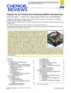
Figure 2. After carrying out a CT scan, we used InVesalius software to generate a 3D model of the skull from DICOM files.
Ac ce pt e
296 297
d
295
2.2. Generating a 3D model of the brain
299
To aid the planning and design of our customized implants, we carried out
300
anatomical MRI scans and generated 3D models of the brain to identify regions
301
of interest. This non-invasive approach allowed us to optimize the location of
302
each implant, and tailor it to the anatomy of individual animals. For animals that
303
received multiple implants, such as a head post and a recording chamber or a
304
head post and a pedestal anchorage base, we verified that the implants were
305
spaced sufficiently far apart from each other. Where possible, we conducted our
306
MRI scans before implanting the animals with a titanium head post, to ensure
307
that the MRI images would be free of metal-induced artefacts.
308 309
The MRI scans were acquired in a Philips Ingenia CX 3T scanner, with a 3D T1-
310
TFE gradient echo pulse sequence, SAG SENSE parallel imaging, a matrix size of
12
Page 12 of 53
311
512, a slice thickness of 0.5 mm, an increment of 0.5 mm, sequential acquisition
312
of slices, and TE = 7.3 ms, TR = 15.9 ms, and flip angle of 8°. The anaesthesia
313
protocol was identical to that of the CT scans, as described in section 2.1.
314 Segmentation of the brain could be performed in either one of two ways: largely
316
automatically on a Linux operating system, or semi-automatically on a Windows
317
or Mac platform. For automatic segmentation of the whole brain (Linux), we
318
converted the DICOM images that were generated from the MRI scans into
319
compressed NIfTI files using either the dcm2nii or dcm2niix tool (Li et al. 2016,
320
https://www.nitrc.org/projects/dcm2nii/) and processed them in FSL 5.0.9
321
(FMRIB, Oxford, UK, https://fsl.fmrib.ox.ac.uk/fsl/fslwiki/FSL). The Brain
322
Extraction tool (BET) v2.1 was used for skull stripping, to generate the isolated
323
brain volume. Next, the FAST automatic segmentation tool was used to
324
differentiate between cerebral spinal fluid, white matter and grey matter,
325
generating output volumes for these three types of tissue. The segmented
326
volume was then imported into 3D Slicer 4.4.0, where the tissue types were
327
converted into 3D models using the Model Maker function, and exported in STL
328
format (Figure 3). For a more detailed description of how this was carried out,
329
please refer to the document titled, ‘Automatic brain segmentation’ in the
330
Supplementary Information.
332 333 334
cr
us
an
M
d
Ac ce pt e
331
ip t
315
Figure 3. We performed automatic extraction and tissue segmentation of the whole brain from MRI data using FSL software (A), and converted the segmented volumes into surfaces using 3D Slicer (B).
13
Page 13 of 53
For segmentation of individual brain regions (e.g. the superior colliculus and
336
visual cortex), or for segmentation of the whole brain on non-Linux operating
337
systems, we imported the DICOM images from the MRI scans directly into 3D
338
Slicer. We identified regions of interest with the aid of a stereotaxic atlas (The
339
Rhesus Monkey Brain in Stereotaxic Coordinates, Paxinos et al. 1999), and we
340
performed slice-by-slice semi-automatic segmentation of the brain or region of
341
interest using the Editor module (Figure 4). For a more detailed description of
342
how this was carried out, please refer to the document titled, ‘Slicer manual’ in
343
the Supplementary Information. We then generated models of brain tissue and
344
exported them as STL files.
345 346 347
Figure 4. We performed manual segmentation of the brain (green regions) on MRI data using 3D Slicer
348
Ac ce pt e
d
M
an
us
cr
ip t
335
software.
2.3. Generating a 3D model of blood vasculature
349
The brain is supplied by a vast network of vessels, with some of the large vessels
350
located on the surface of the brain, and cortical arteries and veins running
351
perpendicular to the surface (Weber et al. 2008). For studies in which large
14
Page 14 of 53
352
numbers of electrodes are inserted into the cortex (for example, using Utah
353
arrays from Blackrock Microsystems), we hypothesised that it would be useful to
354
non-invasively obtain anatomical models of the brain vasculature, prior to
355
surgical insertion of the arrays. This would aid the planning of the layout of
356
arrays upon the cortical surface, and avoid damaging large blood vessels. We
357
tested the feasibility of this approach in one animal.
ip t
358
In this animal, a contrast-enhanced MR angiography (CE-MRA) was performed
360
during an MRI scan session, to identify the anatomical location of blood vessels.
361
This was carried out in a Philips Ingenia CX 3T scanner, with a T1-FFE gradient
362
echo pulse sequence, window width = 795 HU, window level = 408 HU, a matrix
363
size of 336, a slice thickness of 1 mm, an increment of 0.5 mm, a coronal
364
acquisition orientation, sequential acquisition of slices, TE = 1.9 ms, TR = 4.0 ms,
365
and flip angle of 18°. The animal was anaesthetised (as described in section 2.1)
366
and head-fixed in a stereotaxic frame to ensure stability of the image. A
367
gadolinium tracer (0.15 ml/kg), also known as contrast dye, was intravenously
368
infused, followed by an infusion of 0.9% NaCl to flush out the contrast dye. Two
369
sequences were obtained: one prior to infusion of gadolinium, and the other
370
during the infusion of gadolinium. Using the MR scanner software, the sequence
371
that was obtained in the first series was subtracted from that obtained in the
372
second, and a maximum intensity projection (MIP) of the subtraction data was
373
generated, allowing the visualization of blood vessels of ≥ 0.4 mm in diameter.
us
an
M
d
Ac ce pt e
374
cr
359
375
We imported the MRA subtraction images (in DICOM format) into InVesalius,
376
and used the software to segment the images via automated threshold setting.
377
We generated a 3D model of the vasculature, which we then exported in STL
378
format.
379
15
Page 15 of 53
384
ip t
cr
Figure 5. We performed an MRA in one animal, and visualized the blood vessels InVesalius software (left).
We generated a 3D model of the blood vessels, and aligned it with 3D models of the brain and skull using 3D Slicer.
us
380 381 382 383
2.4. Alignment of models
We imported the STL models of the skull, brain tissue, and blood vessels into
386
MeshLab 1.3.4 beta, and removed loose fragments using the Cleaning and
387
Repairing tool, ‘Remove isolated pieces with regard to diameter.’ The Laplacian
388
smoothing function was used to smooth the surfaces of the models.
M
389
an
385
We exported the cleaned and smoothed models as STL files, and imported them
391
into 3D Slicer. The models of the skull, brain, and blood vessels were manually
392
aligned using the Transformation module in 3D Slicer (Figure 5, Figure 6). We
393
then exported the transformed models as STL files for further processing.
Ac ce pt e
394
d
390
16
Page 16 of 53
ip t cr us an
M
areas (green) were coarsely segmented and aligned with the skull using 3D Slicer. We used anatomical landmarks, such as the occipital ridge (indicated by the arrow), to identify the sites of craniotomies and implants.
d
400
Figure 6. Different regions of the visual cortex, such as V1 and V2 (purple), V3 and V4 (yellow), and other
2.5. 3D modelling of implants
Ac ce pt e
395 396 397 398 399
401
Software that is used for 3D modelling and design can be broadly categorized
402
into two groups: some are optimized for the design of top-down, precisely
403
engineered objects (e.g. tools and mechanical parts), while others are better
404
suited for the creation and handling of complex, naturalistic-looking objects (e.g.
405
animals and plants). A few are capable of handling both types of data.
406 407
For the in-house creation of most of our customized objects (head posts,
408
craniotomy guides, and pedestal anchorage bases), we used a combination of
409
Autodesk Inventor Professional 2015 and Blender 2.76 software. Blender is a
410
free, open-source 3D engineering and design software that is suitable for the
411
modelling of mechanically engineered parts, while being powerful and agile
412
enough to handle complex biological data. Hence, it had the advantage of being
413
able to perform all the modelling functions that we needed, while being freely
414
available. For the modelling of parts with simple geometry, we also used
17
Page 17 of 53
Inventor, a proprietary software that is popular for 3D mechanical design.
416
However, we found it to be less suitable for working with biological data, as
417
attempts to import a model of a complex structure such as the skull would cause
418
the software to crash when running on an Intel® Core ™ i7-4771 HP computer
419
with 32 GB of usable RAM. Other software packages, such as SolidWorks
420
(Dassault Systemes) and 3-matic (Materialise), are proprietary software that
421
accomplish similar tasks to Blender, and our recording chambers were designed
422
by an external contractor using SolidWorks. We note, however, that these
423
models could also have been made free-of-charge using Blender. For more
424
detailed instructions on how to use Blender for modelling of customized objects,
425
please refer to the document titled, ‘Blender manual’ in the Supplementary
426
Information.
us
cr
ip t
415
an
427
For each of the 3D-designed objects, we identified key anatomical landmarks,
429
such as the locations of targeted brain regions and the occipital ridge (indicated
430
by the arrow in Figure 6). We used these to plan the precise position and design
431
of implants, optimize the site of craniotomies, and ensure that in the case of
432
animals with multiple implants (e.g. a head post and a recording chamber), the
433
implants were spaced apart from each other. In some cases, particularly when
434
planning the site of craniotomies for electrophysiology, the region of interest
435
was identifiable primarily through stereotaxic coordinates, rather than
436
anatomical landmarks. When we designed our recording chambers, for example,
437
we used stereotaxic coordinates to determine the precise location of the
438
chamber on the skull (more details are provided in section 2.7). Certain features
439
could not be 3D printed (e.g. screw threads, narrow pins, grooves, and small
440
holes), and hence required manual machining. Our mechanical engineers advised
441
us on the design of these features. For example, we ordered taps and dies to
442
create screw threads of the desired sizes on the head posts and pedestal
443
anchorage base, and ensured that the design of the prints allowed them to be
444
clamped securely during the addition of screw threads.
Ac ce pt e
d
M
428
18
Page 18 of 53
445
2.6. Modelling of head posts for head fixation The design of the top portion of the head post was standardized across animals,
447
to ensure compatibility with lab equipment. We created this part in Inventor,
448
and subsequently imported it into Blender in the STL format. The design called
449
for a screw thread at the top of the head post, which was too fine to be 3D-
450
printed. Hence, we printed this element as a solid rod, and the screw thread was
451
added manually after 3D printing. We modelled the base and legs of the head
452
post using Blender, and tailored them to the curvature of the animal’s skull
453
(Figure 7). When planning the location of our customized head posts, we ensured
454
that the front legs of the head posts were positioned close to but not less than ~2
455
mm from the anterior-most part of the supraorbital ridge (also known as the
456
eyebrow bone). For a more detailed description of how this was carried out,
457
please refer to the document titled, ‘How to create a custom-designed head post’
458
and the template file, ‘template_head_post.blend’ in the Supplementary
459
Information.
M
an
us
cr
ip t
446
Ac ce pt e
d
460
461 462 463 464
Figure 7. Head posts with customized bases and legs were modeled using a combination of Inventor and Blender software. The anteriormost parts of the head posts were positioned several milimetres away from the supraorbital ridge (indicated by the arrow).
19
Page 19 of 53
465
2.7. Modelling of recording chambers For our superior colliculus (SC) experiments, we planned the position of the
467
recording chambers using the external ear canals as stereotaxic landmarks to
468
obtain the location of AP0, and identified the horizontal plane that passed
469
through the interaural line and the infraorbital ridge. We used a stereotaxic atlas
470
(Paxinos et al. 1999) to locate the SC, and segmented the structure using 3D
471
Slicer. We generated three perpendicular model planes, and positioned them
472
such that one plane passed through the interaural line and the infraorbital ridge,
473
another passed through the midsagittal plane, and the last passed through the SC
474
(Figure 8). STL files containing models of the skull, SC, and planes were sent to
475
an external contractor, who designed the chamber using SolidWorks software.
476
To ensure that the SC would be accessible to electrodes that were inserted
477
through the chamber, the chamber was oriented to match the trajectory of
478
electrodes, and centred on the point of intersection between the skull and the
479
two planes that ran through the SC. The legs and base of the chamber were
480
custom-fit to the curvature of the skull.
cr
us
an
M
d Ac ce pt e
481
ip t
466
20
Page 20 of 53
ip t cr us an d
M 483 484 485 486 487
Ac ce pt e
482
Figure 8. For superior colliculus recordings, guiding planes were constructed using 3D Slicer software. A cylinder demarcated the volume that would be accessible to depth electrodes, thereby determining the position of our chamber (pink).
2.8. Modelling of pedestal anchorage bases
488
In one of the monkeys, we aimed to chronically implant Utah arrays into the
489
right hemisphere of the visual cortex, and two standard CerePortTM pedestals
490
(Blackrock Microsystems) on the skull over the left hemisphere. This
491
necessitated careful planning of the locations of electrode arrays on the visual
492
cortex, and calculation of the location and size of the corresponding craniotomy.
493
We first carried out a segmentation of the whole brain, as described above, and
494
identified the location of V1 and V4 using anatomical landmarks such as the
495
lunate sulcus. We then determined the boundaries of the craniotomy that would
496
be made during surgery. This allowed us to choose the precise location of our
21
Page 21 of 53
497
implant(s) on the skull, ensuring that they did not overlap with the craniotomy
498
or with the head post (Figure 9).
499 CerePortTM pedestals have a flat base that is not tailored to the curvature of the
501
animal’s skull (Figure 1B), and they sometimes detach from the bone. Hence, we
502
designed a customized pedestal anchorage base that acted as an interface for the
503
two pedestals (Figure 9) while ensuring a close fit to the skull. The upper
504
surfaces of the pedestal anchorage base were designed in Inventor, and included
505
screw holes for the subsequent attachment of the two CerePortTM pedestals. The
506
screw threads themselves were too fine to be 3D printed. We therefore added
507
holes as markers, to which screw threads would later be added. Models of the
508
CerePortTM pedestals and their USB mating interface were also created using
509
Inventor, and all the models were imported into Blender. The CerePortTM models
510
were positioned over the skull, close to but not overlapping each other, to
511
minimize the footprint of the base. The customized base and legs of the
512
anchorage base were generated using Blender, and the two pedestals shared a
513
connecting leg. For a more detailed description of how this was carried out,
514
please refer to the documents titled, ‘How to model a Cereport baseplate’ and
515
‘How to make a wire bundle conduit in a leg’ and the template file,
516
‘template_pedestal_anchorage_base.blend’ in the Supplementary Information.
518
cr
us
an
M
d
Ac ce pt e
517
ip t
500
22
Page 22 of 53
ip t cr us M
an 526
Figure 9. A virtual craniotomy was made in the skull over the right hemisphere, showing the visual cortex
d
520 521 522 523 524 525
of the brain (yellow). A pedestal anchorage base (purple) was created as a support for two CerePortTM pedestals (Blackrock Microsystems, green and orange), and positioned so as to avoid the craniotomy and
Ac ce pt e
519
head post (grey). Note that in this animal, the CT scan of the skull was obtained after the implantation of a (non-customized) head post, hence the skull and head post are fused into one model, and some metalinduced artefacts are visible around the base of the head post.
2.9. Modelling of craniotomy guides as surgical aids
527
The implantation of recording chambers and electrode arrays requires careful
528
planning of the craniotomy, which determines the accessibility of brain regions
529
of interest. As part of our pre-surgical planning, we printed surgical guides to aid
530
us during the operation. These animals had previously received a head post
531
implant for head fixation, which we used as landmark. The craniotomy guide
532
consisted of a ‘grasper’ with a cut-out portion that matched the shape of the head
533
post (allowing the grasper to be fixed to the head post in lock-and-key fashion
534
during surgery), a cutting guide that delineated the boundaries of the
535
craniotomy, and a rod linking the grasper to the cutting guide (Figure 10). For a
536
more detailed description of how this was carried out, please refer to the
23
Page 23 of 53
537
document titled, ‘How to create a craniotomy guide for chamber implantation’
538
and the template file, ‘template_chamber_craniotomy_guide.blend’ in the
539
Supplementary Information.
M
and electrode arrays (right), allowing the trepanations to be made at the desired locations on the skull. Each craniotomy guide consisted of a grasper that could be attached to the head post (blue), and a cutting guide that marked the boundary of the craniotomy.
2.10.
d
546
Figure 10. Craniotomy guides (red) were designed for use during surgical implantation of chambers (left),
Visualization of models
Ac ce pt e
541 542 543 544 545
an
us
cr
ip t
540
547
All the models were exported in STL format. For easy visualization and sharing,
548
3D PDF files were generated through a multistep process, which required a
549
combination of software tools. First, each of the models that were associated
550
with an individual animal, such as the skull, the brain, and the implant(s), were
551
imported into MeshLab in STL format, and exported as OBJ files. The OBJ files
552
were then imported into a new project in DAZ Studio 4.7 (Win and Mac,
553
https://www.daz3d.com/daz_studio), and the project was saved as a single U3D
554
file, containing all the models. We downloaded and modified a LaTeX script (Win,
555
Mac and Linux), U3D2PDF (http://www.wiki.david-3d.com/making_a_3d_pdf),
556
and generated an interactive PDF rendering from the U3D file. The 3D PDF file
557
could be shared easily amongst collaborators, and opened in Adobe Acrobat
558
Reader, affording viewers a rotatable and zoomable 3D view of the design. For a
559
more detailed description of how this was carried out, please refer to the
24
Page 24 of 53
560
document titled, ‘How to create a 3D PDF’ and the sample LaTeX code,
561
‘sample_3D_PDF_tex_code’ in the Supplementary Information.
562
2.11.
3D printing
We identified 3D printing companies in our region through the online search
564
platform, 3dhubs.com, which allowed us to select printing companies based on
565
the print material, model of the machine, print resolution, geographical location,
566
price, and customer reviews. We consulted various 3D printing companies to
567
ensure that our designs could be printed in precise detail, and that their print
568
resolution would be adequate for the task at hand. Table 1 displays the mean
569
cost of each print.
us
cr
ip t
563
570
Occasionally, our printers identified minor errors in our models that prevented
572
them from being printed, such as unintended holes and non-manifold edges. We
573
performed mesh repair and clean up using Meshmixer 3.2 software (Win and
574
Mac, http://meshmixer.com). Meshmixer is a popular free software (Autodesk,
575
Inc.) with an ‘Inspector’ tool, allowing the user to analyse a model for errors or
576
irregularities, and fix them rapidly. The software generated solutions to fill small
577
holes and delete unwanted regions- an automated approach that saved us from
578
the substantial time and effort that usually accompanies manual repair.
M
d
Ac ce pt e
579
an
571
580
For cheap and rough rapid prototyping of objects such as the skull, prints were
581
made from acrylnitrile butadiene styrene (ABS) or polylactic acid (PLA) plastic,
582
through a process known as fused deposition modelling (FDM).
583 584
For rapid prototyping of objects such as head posts, chambers, pedestal bases
585
and pedestals, we wanted high-quality prints that would closely resemble the
586
final titanium product, with the preservation of fine details. Similarly, our
587
craniotomy guides needed to be accurate in form, but did not have to be made of
588
a strong or expensive implantable material such as metal. For these applications,
589
resin prints were made using stereolithography (SLA), with a Form 1+ 3D
590
printer (Form Labs, Somerville, MA), offering 25-micron resolution in the
25
Page 25 of 53
591
vertical dimension. Additionally, prints of segmented cortical tissue were made
592
in resin, and used as anatomical references.
593 The final implants were printed by an industrial 3D printing company in Grade 1
595
titanium, using a process known as direct metal printing (DMP). The dimensions
596
of the printed parts had an accuracy of ±50 microns, which was adequate for our
597
purposes.
598
Mean cost per unit (€)
Head post
P
2
Pedestal base
P
1
Craniotomy guide
F
5
27.68
Cortex
R
1
36.97
Head post
F
7
399.00
Pedestal base
F
1
355.02
Chamber
F
2
503.83
Skull
R
7
36.74
21.71
43.14
M
PLA plastic
Number of units
cr
Titanium
Version
us
Resin
Print
an
Material
ip t
594
599 600 601 602 603 604 605
Table 1. Average cost of each type of print, categorized by material, object, and version (P: prototype; F: final
606
For a more detailed description of how this was carried out, please refer to the
607
document titled, ‘How to 3D print an object’ in the Supplementary Information.
object; R: anatomical reference). For rapid prototyping, prints were made from PLA plastic or resin. The craniotomy guides that were used during surgery were printed in clear resin, while the final versions of
d
implants such as the head posts, chambers, and pedestal anchorage base, were printed in Grade 1 titanium.
Ac ce pt e
The prices include the cost of post-production that was carried out within the 3D manufacturing company, but do not include post-production that was carried out by our workshop. They also exclude the cost of adding a biocompatible coating to the base (described in the section ‘Osseo-compatible coating.’)
2.12.
Post-processing
608 609
After printing, we carried out further post-production processing. We removed
610
support structures from all the objects. We added external screw threads to the
611
head posts. One of our head posts had a minor defect, causing two of the legs to
612
be bent at an odd angle. We used pliers to bend them into the correct shape.
613 614
For the chambers, we added ridges and pins. A disadvantage of 3D printing is
615
that the resolution of the printed objects (~25 µm for resin, ~50 µm for titanium,
616
and ~200 µm for PLA plastic) is typically worse than that which is achievable
617
through CNC machining (~2 µm). As a result, the surface quality of 3D-printed
26
Page 26 of 53
618
objects is worse than that of CNC-machined objects. We found that this did not
619
affect the overall quality and functionality of our printed objects, except for the
620
interior surface of our chambers, which had to be smoothened in order to
621
facilitate cleaning and reduce the risk of infection. Hence, the interior wall of the
622
chambers was electro-polished to a roughness of Ra < 0.05 µm (yielding slight
623
thinning of the material).
ip t
624
For the pedestal anchorage base, we added internal screw threads to the holes
626
on the upper surface. Note that these holes were not oriented perpendicular to
627
the surface, but at an angle of 17.5 degrees, to match the angle of the screw holes
628
on the base of the CerePortTM pedestals. Hence, a special clamp was made to hold
629
the pedestal anchorage base firmly in the correct position and set it at the
630
correct angle during the addition of screw threads (Figure 11).
631 632 633
Figure 11. To add internal screw threads to the holes on the upper surface of the pedestal anchorage base, a special clamp was designed, positioning the holes at a 17.5-degree angle.
634
Examples of the printed objects are shown in Figure 12.
Ac ce pt e
d
M
an
us
cr
625
27
Page 27 of 53
ip t cr us M
an 639
Figure 12. 3D-printed objects for primate electrophysiology: a head post (A), a pedestal base (B) and a
average printing cost.
d
chamber (C) made from titanium, and a craniotomy guide made from resin (D). The price indicated is the
Ac ce pt e
635 636 637 638
2.13.
Osseo-compatible coating
640
Hydroxylapatite (HA) is a synthetic form of calcium phosphate (a naturally
641
occurring component of bones and teeth), which is popularly used as a
642
biomaterial for bone repair and substitution (Surmenev et al. 2014; LeGeros
643
2016). Commercial orthopaedic and dental implants are coated with HA
644
granules, to promote osseointegration between the bone and the implant
645
(Søballe et al. 1990; Cook et al. 1992; Lanz et al. 2013; Raphel et al. 2016). The
646
bottom surfaces of our implants were plasma sprayed with HA by the company
647
Medicoat AG (Mägenwil, Switzerland), at a cost of €230 per implant. Note that
648
this procedure is not widely adopted in the field of primate neurobiology, and we
649
have previously observed successful osseointegration of implants that were not
650
coated with HA. Hence, to our knowledge, the benefits of doing so are neither
651
well-researched nor well-established in monkeys. Nevertheless, we felt that the
652
potential benefits merited the additional expenditure. A 30-micron titanium
28
Page 28 of 53
bond layer was added to the lower surfaces of the legs and base, followed by a
654
50-micron layer of HA. During the coating process, the screw holes were masked
655
to prevent alterations of their dimensions and surface smoothness. For a more
656
detailed description of how this was carried out, please refer to the document
657
titled, ‘How to order a coating of hydroxylapatite’ in the Supplementary
658
Information.
659
2.14.
ip t
653
Surgical procedure
All experimental surgical procedures complied with the NIH Guide for Care and
661
Use of Laboratory Animals (National Institutes of Health, Bethesda, Maryland),
662
and were approved by the institutional animal care and use committee of the
663
Royal Netherlands Academy of Arts and Sciences.
an
664
us
cr
660
A course of antibiotics was started two days prior to each operation, and the
666
animal was weighed to obtain the correct dosage. Anaesthesia was induced with
667
intramuscularly administered ketamine (7 mg/kg) and medetomidine (0.08
668
mg/kg). We administered 0.1 ml atropine (concentration 0.5 mg/ml) if the heart
669
rate dropped below 75 bpm. The animal was placed on a heated mat to allow
670
continuous regulation of body temperature. Eye ointment was applied to
671
maintain hydration of the eyes. Xylocaine ointment was applied to the ear bars of
672
the stereotaxic frame, and the animal’s head was secured in the frame.
d
Ac ce pt e
673
M
665
674
For maintenance of anaesthesia, the animal was intubated and ventilated with
675
0.8-1.5% isoflurane (20% O2 and 80% air). An intravenous catheter was inserted
676
into a vein in the arm. During surgical implantation of head posts and chambers,
677
we administered fentanyl at 0.005 mg/kg on indication, Ringer-glucose at 10-15
678
ml/kg/hour, and antibiotics intravenously. During surgical implantation of
679
electrode arrays, we additionally administered midazolam at 0.5 mg/kg
680
(concentration 5 mg/ml) once per hour. ECG, heart rate, external blood pressure,
681
SpO2, CO2, temperature, muscle tone, respiration, and the response to pain
682
stimuli were monitored continuously. The head was shaved and cleaned with
683
chlorhexidine solution and alcohol. For installation of cranial implants, a semi-
684
circular flap of skin was carefully detached from the skull over the desired
29
Page 29 of 53
685
implant location, reflected, and wrapped in damp cotton swabs to keep it moist.
686
Methods of implanting a head post, chamber, and pedestal anchorage base, and
687
post-surgical recovery are described separately in the following sections.
688 689
2.14.1. Head post implantation The titanium head post was autoclaved to ensure sterility. The implant was
691
placed on the skull, with the front legs positioned close to the brow ridge, and
692
adjusted such that it fit perfectly against the skull. We used 2-mm-diameter Ti
693
cortex screws (DePuy Synthes, Amersfoort, Netherlands) to secure the head post
694
to the bone. A small incision was made in the flap of skin, just large enough to
695
allow egress of the head post, and the skin was then pulled over the head post,
696
covering its legs. We positioned the hole in such a way that slight tension was
697
maintained on the skin. The wound margins were sutured together, and an extra
698
stitch was made around the base of the protruding section of the head post, to
699
hold the skin closed around the newly made hole.
700 701
2.14.2. Chamber implantation
M
an
us
cr
ip t
690
Prior to use, we sterilized our resin craniotomy guide by soaking it in alcohol for
703
30 min, and we autoclaved the Ti chamber. For the implantation of chambers
704
(and electrode arrays), in addition to stereotaxic coordinates, we used a
705
craniotomy guide to identify the precise location of the craniotomy, as
706
determined during pre-surgical planning (Figure 10). First, the guide was affixed
707
to a head post, which had been implanted during an earlier procedure. Next, the
708
circumference of the desired craniotomy was traced using a marker pen, and the
709
craniotomy was made with a trepan. The chamber was positioned over the
710
circular craniotomy and secured to the bone with Ti screws. A small incision was
711
made in the flap of skin, just large enough to allow egress of the chamber. The
712
skin was pulled back over the legs of the chamber and sutured closed. To seal off
713
the chamber, we used a cap from Crist Instrument Co., Inc (Hagerstown, MD),
714
which had an interior rubber ring and was secured using three screws that
715
protruded into a groove running around the outer diameter of the chamber.
Ac ce pt e
d
702
716 717
2.14.3. Pedestal anchorage base implantation
30
Page 30 of 53
The titanium pedestal anchorage base was autoclaved to ensure sterility. The
719
implant was adjusted until its position on the skull was correct. Ti screws were
720
used to secure the anchorage base to the bone. We filled the screw holes with
721
bone wax to prevent tissue and fluid egress during the recovery period, in which
722
we expect integration of the implant with the bone. The skin was pulled back
723
over the entire implant and sutured closed. We plan to attach the CerePortsTM
724
during a second surgery in which the arrays will be inserted into the visual
725
cortex.
ip t
718
727
cr
726 2.14.4. Recovery
Ten minutes before the end of the surgery, the ventilator was switched to stand-
729
by mode, allowing spontaneous breathing. Upon conclusion of the procedure, the
730
monkey was released from the stereotactical apparatus. The isoflurane was
731
switched off and an antagonist was administered i.m. (atipamezole 0.008
732
mg/kg), allowing the animal to wake up. Subjects were closely monitored
733
following the operation and given several weeks to recover. For the animal that
734
received a pedestal anchorage plate, a minimum interval of two months is
735
planned between the implantation of the anchorage plate and the implantation
736
of the electrode arrays and CerePortsTM. Postoperative care included analgesia
737
with finadyne i.m. (1-2 mg/kg) on the day of the surgery, followed by oral
738
Metacam that was spread on pieces of fruit or mixed with syrup, at 0.1 mg/kg
739
per day, for the six days following the surgery.
an
M
d
Ac ce pt e
740
us
728
3. Results
741 742
Compared to non-customized mass-produced implants, our 3D-printed implants
743
were faster and easier to implant, as their base was already optimally or close-
744
to-optimally shaped. For one of our chambers (described in detail below), we
745
had to bend the legs slightly with pliers to obtain a good fit. The other implants
746
needed no further modification during surgery. In all cases, including those
747
where our implants were manually adjusted, we observed little to no gap
748
between the base of the implant and the skull (Figure 13), reducing the chances
31
Page 31 of 53
749
of tissue and fluid ingress, and subsequent bacterial infection and tissue
750
inflammation.
751 At the time of implantation, most of our animals were juveniles, aged 4 to 7 years
753
old, and the time interval between their anatomical scan and the date of
754
implantation was up to 10 months. This raised the question of whether normal
755
cranial development and growth would lead to changes in their bone structure,
756
adversely affecting the fit of the implant. During surgery, however, we observed
757
no effect of elapsed time on the fit of the implant.
cr
ip t
752
d
762
Figure 13. During surgical implantation, our customized implants sat flush against the surface of the skull, leaving little room for fluid ingress.
Ac ce pt e
759 760 761
M
an
us
758
3.1. Chamber implantation
763 764
In one of the animals that received a chamber, the location indicated by the
765
craniotomy guide perfectly matched that of the stereotaxic coordinates. In the
766
other animal, however, we noticed a discrepancy of approximately 1 cm between
767
the location predicted by the surgical guide and that based on stereotaxic
768
coordinates. We positioned the craniotomy based on the location prescribed by
769
the surgical guide. However, after making the craniotomy and inserting the
770
bottom lip of the chamber into the hole, we found that the chamber legs did not
771
fit perfectly against the bone, making it unlikely that our implantation location
772
was exactly as planned. Hence, we bent the legs with a pair of pliers to match the
773
skull.
774
32
Page 32 of 53
In both animals, we found that the craniotomies were slightly too large, hence we
776
filled the gap with dental acrylic. We suspect that this was due to a small
777
mismatch between the size of the hole made by the trepan and the planned size
778
of the chamber. In one animal (the one for which a manual adjustment of the
779
chamber legs was made), the gap was located on only one side of the chamber
780
and measured less than half a millimetre, hence requiring only a small amount of
781
dental acrylic, whereas in the other animal, the gap was larger (although still
782
smaller than 1 mm) and we built up a small layer of dental acrylic around the
783
implant. We plan to make small adjustments to the design of the chambers in
784
future, to prevent the mismatch in size.
785
3.2. Pedestal anchorage base implantation
us
cr
ip t
775
To position the pedestal anchorage base on the skull, we did not need to use a
788
surgical guide as this could easily be done by eye. One of the legs of the implant
789
had a distinctive shape that allowed it to fit snugly against the curvature of the
790
occipital ridge (a prominent protrusion of the bone in macaques, as shown in
791
Figure 6), and we adjusted the position of the implant until a close fit was
792
obtained. We did not observe any gaps between the skull and the implant. Hence,
793
we did not need to modify the legs or use dental acrylic.
M
d
Ac ce pt e
794
an
786 787
3.3. Implant integration
795 796
At the time of writing, the post-surgical implantation period ranged from 11
797
months to ~2 years and none of our animals developed problems with their
798
customized implants.
799 800
In the animals that received customized head posts, we generally observed little
801
retraction of the skin (Figure 14, left panel), indicating improved health of the
802
surrounding tissue, and good integration between the customized head posts
803
and the skin. This contrasts with our previous experience with non-customized
804
head posts, where we noticed that the skin surrounding the implants sometimes
805
retracted by several millimetres.
806
33
Page 33 of 53
ip t
Figure 14. The skin surrounding the customized head post implants showed no signs of retraction in some animals (left), and up to 3 mm of retraction in others. One animal received a pedestal anchorage base (right) and the skin over the implant was healthy, with little sign of the procedure in the months after surgery.
cr
807 808 809 810
us
811
For one of the animals that received a customized head post, we carried out a
813
post-operative MRI scan, allowing us to visualize the effects of the metal head
814
post on the quality of the scan. We observed significant artefacts in the region of
815
the brain underlying the head post, extending approximately one centimetre
816
from the base of the head post and occluding the anatomy of the frontal cortex
817
(Figure 15). However, we were still able to obtain a clear view of the temporal,
818
parietal, and occipital lobes, and visualize the visual cortex (our region of
819
interest in that animal).
M
d
Ac ce pt e
820
an
812
34
Page 34 of 53
ip t cr us an M
d
826
Figure 15. The titanium head post generated artefacts in a post-operative MRI scan (demarcated by white arrows, top), disrupting the signal in the vicinity of the head post and obscuring the anatomy of the frontal lobe. The resulting distortions in the shape of the brain (demarcated by green arrows, bottom) closely followed the contours of the legs of the head post.
Ac ce pt e
821 822 823 824 825
827
At the time of writing, the chambers had been implanted for 13 and 16 months
828
respectively. After surgery, we cleaned the chambers regularly using hydrogen
829
peroxide and betadine solution. The electropolished interior walls were smooth
830
and easy to clean. We did not observe any loss of fluid from the chambers, and
831
they remained stable and free of infection. In one of our animals, the base and
832
legs of the chamber were not covered with dental acrylic. In this animal, the skin
833
around the chamber remained healthy, with less than 2 mm of retraction around
834
the cylinder base, but retraction occurred over the anterior-most leg of the
835
chamber.
836 837
A pedestal anchorage base was implanted in one animal for eight months at the
838
time of writing. The skin was closed back over the implant, allowing the wound
839
to heal fully after the surgery. The overlying skin was healthy with normal fur
840
growth, and the site of implantation was no longer visible a few months after
35
Page 35 of 53
841
surgery (Figure 14, right panel), although we were able to feel the raised edges
842
of the anchorage base when palpating the skin.
843 This same animal had previously been implanted with a non-customized head
845
post. For reasons unrelated to the implantation of the customized pedestal
846
anchorage base, the head post came loose and we carried out a CT scan in order
847
to assess the integrity of the skull underneath the head post. This gave us the
848
opportunity to non-invasively visualise the pedestal anchorage base as well. The
849
metal implant created substantial artefacts in the image, which were identifiable
850
by their bulky forms and jagged surfaces (Figure 16). We palpated the skin and
851
verified that these structures were indeed artefacts and were not actually
852
present.
us
cr
ip t
844
Ac ce pt e
d
M
an
853
854 855 856
Figure 16. A CT scan revealed the overall contours of the pedestal anchorage base, although numerous artefacts were generated in the image, due to the metallic nature of the implant.
857
4. Discussion
858
We here described how 3D printing could be used as a powerful tool to speed up
859
surgery time, deliver customized results, and potentially reduce subsequent risk
860
of infection and implant failure. These new techniques were embedded within a
861
larger process, which included more traditional techniques, and substantial
862
planning and post-processing. Setting up a workflow, compiling the requisite
863
software tools, and finding reputable contractors to carry out the printing
864
process required an initial investment of time and energy. Once our protocols
865
were in place, however, this information could be shared readily and used to
36
Page 36 of 53
866
generate a wide range of well-tailored products. In this Discussion, we cover
867
various aspects of the process, and provide insight into the challenges and
868
advantages of this approach.
869
4.1. Support and infrastructure While 3D printing is a highly innovative and even revolutionary technology,
872
representing the forefront of digital design and automated production, the
873
present methods also rely upon an ecosystem of manual labour and machining.
874
Critical to our approach was ready access to MR and CT scanning facilities, along
875
with logistical and technical support, which allowed us to generate 3D models of
876
our animals’ anatomy. An alternative strategy is to carry out a surgical survey, in
877
which the skin is temporarily retracted and a mould is taken of the skull, forming
878
the basis for future modelling (Betelak et al. 2001). However, obtaining a cast of
879
the skull is labour-intensive and time-consuming. We also believe that CT or MR
880
scanning is preferable because it avoids an additional surgical procedure.
881
McAndrew et al. (2012) have previously attempted to perform a non-invasive
882
‘skull mapping’ procedure in an awake animal, using a stereotaxic needle to scan
883
the head in three dimensions (with the skin intact) in order to generate a 3D
884
representation of the skull. However, this failed to accurately capture the
885
morphology of the skull (perhaps due to the overlying muscle and skin tissue),
886
and the authors abandoned this approach for MRI and CT data acquisition.
cr
us
an
M
d
Ac ce pt e
887
ip t
870 871
888
Throughout the design process, we worked closely with our mechanical
889
workshop and 3D printing service providers, obtaining advice on the design
890
considerations to be taken with our prints. Some of these arose from the
891
constraints imposed by 3D printing technology, while others were related to
892
principles in engineering, such as the calculation of tolerances, dimensions of
893
screw holes and screw threads, and material strength. If we anticipated that
894
certain tools might be needed during the post-processing stage, such as thread
895
cutters or clamps with which to securely hold our prints, these were ordered or
896
made in advance by our workshop.
897
37
Page 37 of 53
898
With a choice of numerous rapid prototyping companies in our region, we had
899
our plastic and resin prints made by several service providers, and selected the
900
providers who offered the best value. On occasion, prints were ready for
901
collection as soon as the day after placement of the order. The prompt service
902
and good print quality allowed the production process to proceed rapidly.
903 For our titanium prints, we benefitted from geographical proximity to both a
905
leading industrial 3D printing company, and a medical coating company
906
(MediCoat, Switzerland). Due to their short production times, we typically
907
received our new titanium prints within three weeks from the date that the
908
order was placed, while coating of prints with HA took one to two weeks from
909
the date that the medical coating company received the implant.
us
cr
ip t
904
an
910
After the titanium parts were printed, post-processing work included electro-
912
polishing of the interiors of chambers, which was carried out by a third-party
913
company. Our mechanical workshop added ridges and pins to chambers, and
914
screw threads to head posts and the pedestal anchorage base. Two of our head
915
posts had slight defects due to printing and/or design errors; however, we were
916
able to rectify them easily by bending the legs with pliers.
d
Ac ce pt e
917
M
911
4.2. 3D printing materials
918 919
The machines on which our prints were built ranged from desktop printers, such
920
as the Ultimaker and the Form, to industrial printers that printed in metal.
921
Whenever possible, we printed high-quality prototypes to check and evaluate
922
our designs, before printing them at higher cost in titanium. The relatively low
923
cost of the prototype prints allowed us to take advantage of the benefits offered
924
by 3D printing: the ability to quickly create unique, complex implants that were
925
customized to individual animals, and freedom from the design constraints
926
imposed by traditional CNC milling methods.
927 928
To ensure that our designs would be printable, we acquired a basic
929
understanding of how various 3D printers work. FDM printers (for plastic
930
prints) build their objects in the air, layer by layer, while SLA printers (for resin 38
Page 38 of 53
prints) build their objects from a solution. During the printing process, both FDM
932
and SLA printers add extra material known as ‘support structures’ to the print.
933
The support structures act as scaffolds and prevent the print from deforming due
934
to gravity. Many commonly used FDM printers, such as the Ultimaker, are
935
hobbyist machines, which tend to produce their prints relatively quickly and at
936
low resolution. They build prints out of plastics that have low melting
937
temperatures, and can often yield uneven results. Due to the properties of the
938
print material and the deposition process, FDM prints can be fragile, especially at
939
thin points. Similarly, when it comes to printing using SLA, low-cost resin prints
940
tend to become brittle when exposed to UV light and may therefore fall apart
941
over time. Hence, unless these low-cost plastic or resin prototypes are intended
942
for short-term use, their form should be robust in design. We do note, however,
943
that the range of materials on offer continues to expand. For higher prices, it is
944
possible to produce prototypes using materials that confer properties such as
945
additional strength, toughness, biocompatibility, and flexibility to the prints.
cr
us
an
M
946
ip t
931
Unlike plastic and resin prints, titanium prints are built up layer by layer within a
948
bed of metal titanium particles. Hence, they do not require additional structures
949
to support their weight. The titanium particles are fused together at high
950
temperatures by a laser beam, yielding extremely strong, durable prints, which
951
accounts for the popularity of this technique in the aerospace, automotive, and
952
health industries. Medical implants are typically manufactured using medical-
953
grade titanium, and various methods of enhancing their biocompatibility are
954
under development. These include the coating of implants with osteocompatible
955
materials such as calcium phosphates, the embedding of bactericidal silver
956
particles into the osteocompatible coating (Valle et al. 2012; Lanz et al. 2013),
957
and the creation of nano-scale pores on the surface of the implants via metal
958
laser sintering, grit blasting, or acid etching, in order to promote
959
osseointegration (Buser et al. 1991; Hacking et al. 2012; Raphel et al. 2016).
960
Titanium has the added advantage of being ductile enough to be bent manually
961
with pliers, if the need arises (e.g. during surgical implantation of one of our
962
chambers, we performed manual bending of the legs, due to a discrepancy
963
between the planned and actual location of the implant).
Ac ce pt e
d
947
39
Page 39 of 53
964 We note that if an animal with a metal implant undergoes a structural MR or CT
966
scan, the implant is likely to distort the magnetic field and produce artefacts in
967
the signal, which may obscure the anatomy of the brain and/or skull in the
968
region of the implant (as seen in Figure 15 and Figure 16). Hence, any anatomical
969
or functional scans of the brain should ideally be obtained prior to implantation
970
with a titanium object, particularly if the location of the implant is close to that of
971
the brain region of interest. Nevertheless, under certain circumstances, it may be
972
useful to carry out an anatomical scan- such as when the researchers want to
973
verify the location of an inserted electrode, or check the quality of the underlying
974
bone and assess the level of integration between the skull and the implant
975
(Adams et al. 2007). We would refrain from performing functional scans in
976
animals with a metallic head post, due to concern over potential overheating of
977
the implant, and also because this is not widely done (further research on the
978
thermal conductance properties of various metals in an MR scanner might be
979
useful). Radiolucent materials, such as PEEK, are widely used in applications that
980
require extensive post-operative scanning (Mulliken et al. 2015), in combination
981
with ceramic (rather than titanium) screws. However, 3D printing in PEEK is still
982
at a relatively early stage of development, hence radiolucent implants are usually
983
manufactured through CNC milling (McAndrew et al. 2012; Lanz et al. 2013).
cr
us
an
M
d
Ac ce pt e
984
ip t
965
985
Besides plastics, resins and metals, biologically inspired materials are starting to
986
be developed. Recently, a study demonstrated the use of a novel synthetic
987
osteoregenerative material, termed ‘hyperelastic bone,’ which is composed of
988
hydroxylapatite (90%) and polycaprolactone or poly(lactic-co-glycolic-acid)
989
(10%) (Jakus et al. 2016). This material could be rapidly 3D printed, and had
990
properties mimicking that of naturally occurring bone, such as high porosity,
991
elasticity and strength. A cranial implant made out of hyperelastic bone was used
992
to repair a defect in the skull of a monkey (Jakus et al. 2016), and the researchers
993
found that it integrated readily with the bone and was well vascularised just four
994
weeks after the surgery, making it a promising material for the creation of future
995
implants in neuroscience.
996
40
Page 40 of 53
4.3. 3D modelling software We explored a wide variety of 3D modelling tools, with a focus on free, open-
999
source software. InVesalius, OsiriX, FSL, and 3D Slicer were used for processing
1000
CT and MR imaging data, while Blender, MeshLab, and DAZ Studio were used for
1001
3D design and rendering. Imaging data is typically stored in the DICOM format,
1002
and is readily accessible through a number of software tools. However, a
1003
plethora of file formats are used in 3D modelling- the most popular of which
1004
include the STereoLithography (STL), OBJect (OBJ), and PoLYgon (PLY) formats.
1005
Each programme was able to handle a specific set of 3D file formats,
1006
necessitating a diverse range of software to cover all the functions required. We
1007
hope that other researchers will be able to take advantage of the proposed
1008
workflow (Table 2), thereby reducing the time needed to identify the necessary
1009
software tools and their interfaces so that they can quickly assemble their own
1010
coherent workflow. We have also assembled a series of reference manuals that
1011
are available for download in the Supplementary Information (please refer to
1012
section 4.6, ‘Sharing amongst researchers’).
M
an
us
cr
ip t
997 998
Obtain anatomical scans of skull
-
DICOM
MRI scan
Obtain anatomical scans of brain and/or blood vessels
-
DICOM
3D modelling of skull
Generate model of skull, identify anatomical landmarks
InVesalius/OsiriX, MeshLab
STL
3D modelling of brain
Generate model of brain, identify anatomical landmarks
3D Slicer/FSL, MeshLab
STL
3D modelling of object
Align anatomical models, design customized objects
3D Slicer, Blender/Inventor
STL
Generate STL/PDF files
Generate STL files for printing and 3D PDF files for sharing
MeshLab, DAZ Studio, LaTeX
STL, OBJ, U3D, PDF
3D print in plastic
Create rapid prototypes using fused deposition modelling
Meshmixer*
STL
3D print in resin
Create high-resolution resin prints using stereolithography
Meshmixer*
STL
3D print in Ti
Create titanium implants using direct metal printing
Meshmixer*
STL
Machining
Post-production processing and correction of defects
-
-
Coating with HA
Coat base of implants with layer of hydroxylapatite
-
-
Craniotomy guide
CT scan
Pedestal base
Output Chamber
Ac ce pt e
File formats
Head post
Software
1
1/2
1/2
1/2
1/2
1/2
1/2
3
3
3
4
4
4
3
5
5
5
3
4
6
6
6
4
5
7
7
7
6
8
8
7
9
9
8
10
10
Brain model
Description
d
Steps
Skull model
1013
1 1 2
3
2
2
4
41
Page 41 of 53
Sterilization
1014 1015 1016 1017
Soak resin prints in alcohol, and autoclave titanium prints
-
-
9
11
11
8
Table 2. Workflow for each type of printed object, listing the software and file formats that were involved. The numbers in the ‘Output’ columns refer to the order of the steps involved. ‘1/2’ indicates that these steps could be performed simultaneously or in any order. *MeshMixer was used only if minor repairs were needed prior to printing.
1018
4.4. Craniotomies In one of our SC animals, our craniotomy guides were combined successfully
1021
with pre-surgical planning and stereotaxic measurements, providing us with
1022
accurate delineations of the craniotomy boundaries. Furthermore, the precisely
1023
tailored fit of our implant helped to verify that it was correctly positioned on the
1024
skull during implantation, as slight deviations from the planned location yielded
1025
a suboptimal fit. In some cases, such customization can reduce or eliminate the
1026
need for researchers to undertake post-hoc imaging studies to determine the
1027
optimal trajectory of electrodes that are inserted through a chamber (Kalwani et
1028
al. 2009). For example, we successfully obtained recordings from the superior
1029
colliculus in one of our animals via a customized recording chamber, without
1030
needing to carry out a post-operative scan (at the time of writing, we have not
1031
started recording from the other animal, but we also expect that a scan will not
1032
be necessary). Nevertheless, these methods are not always foolproof. In one
1033
animal, we noticed a disparity between the surgical guide and the intended
1034
stereotactic coordinates, as well as an imperfect fit between the chamber and the
1035
skull. We expect the likelihood of these mismatches to decrease as researchers
1036
gain experience with these methods.
cr
us
an
M
d
Ac ce pt e
1037
ip t
1019 1020
1038
In both animals, we found that the craniotomy was slightly too large relative to
1039
the diameter of the chamber and we used dental acrylic to fill in the gaps. Hence,
1040
the exact size of the printed chamber should be carefully measured and
1041
compared to the trepan to ensure as close a fit as possible. As an alternative to
1042
dental acrylic, one could consider using Geristore® (DenMat, Lompoc, CA), a
1043
resin ionomer which reportedly offers several advantages over dental acrylic
1044
such as enhanced biocompatibility (Johnston et al. 2016), or a hydroxylapatite
1045
paste such as Mimix QS (Biomet Microfixation, Jacksonville, FL) (Adams et al.
1046
2011).
42
Page 42 of 53
1047
4.5. Design considerations During the 3D modelling process, we considered several designs for our
1050
implants. For example, we tested various configurations for the layout of our
1051
pedestal anchorage base, and adjusted the number of legs and their positions.
1052
During surgery, we found that one of the legs of the anchorage base extended
1053
laterally under the muscle tissue surrounding the implantation site, slightly
1054
impeding access to one of the screw holes. Hence, for future implants, we plan to
1055
generate a 3D model of the overlying skin and muscle tissue from our MRI scans,
1056
to ensure that the legs and screw holes are readily accessible.
us
cr
ip t
1048 1049
1057
All of our designs featured multiple legs per implant. A disadvantage of this is
1059
that the raised profile of the legs may cause the skin to recede from the implant,
1060
eventually exposing the bone (Mulliken et al. 2015). This only occurred in one of
1061
our implants (a chamber), for just one of its legs. The problematic leg was
1062
positioned close to an existing head post, which may have contributed to the
1063
retraction of the skin. An alternative technique, described by Mulliken et al.
1064
(2015) for the creation of customized PEEK chambers, is to embed the screw
1065
holes within the wall of the chamber itself (Mulliken et al. 2015). Downsides to
1066
this approach are that the circumference of the chamber is increased, and the
1067
anchor points of the screws are concentrated within a small region rather than
1068
distributed over a larger area, which may contribute to mechanical instability.
M
d
Ac ce pt e
1069
an
1058
1070
Adams et al. (2007) have reported using titanium head posts with feet of a
1071
similar thickness to ours (1 mm), and they found that 14 months after
1072
implantation, the bone had grown over the feet, partially embedding the head
1073
posts and screws within the skull. We generally observed little retraction of the
1074
percutaneous wound margin in our animals, perhaps due to the precautions
1075
taken during surgery to keep the skin firmly wrapped around our implants, as
1076
well as to the low profile of our feet (~1 mm).
1077 1078
We identified several improvements that could be made to the design of our
1079
chambers. Firstly, we electropolished the interior of our chambers, as well as the 43
Page 43 of 53
upper half of the exterior. In one animal, we found that the lower half of the
1081
chamber exterior tended to accumulate dirt due to its rough surface. Hence, we
1082
plan to electropolish the whole cylinder in future iterations (though not the legs).
1083
Secondly, the design of our chambers included a pin that protruded from the
1084
exterior wall of the chamber; however, during recordings from the SC, we found
1085
that the pin was unnecessary and limited the number of positions that could be
1086
accessed using our microdrive, and we may choose to eliminate the pin from
1087
subsequent designs. Thirdly, our chambers were designed with a lower ‘lip’
1088
around the base of the cylinder, which extended below the surface of the skull,
1089
and enhanced the seal between the chamber and the bone. However, the
1090
presence of the lip prevented us from testing the fit of the chamber legs against
1091
the skull, prior to making the craniotomy. Hence, for future chamber
1092
implantations, we plan to print out a lipless version of the chamber in resin,
1093
which will be used to determine the exact position of the chamber, based on the
1094
fit between the skull and the chamber legs, before carrying out the craniotomy.
1095
We could even combine the lipless resin chamber with our craniotomy guide,
1096
producing a single chamber-craniotomy resin guide.
cr
us
an
M
d
4.6. Sharing amongst researchers
Ac ce pt e
1097
ip t
1080
1098 1099
Once our workflow was established, we were able to share these techniques
1100
easily between lab members. While the base and legs of our implants were
1101
customized to the anatomy of individual animals, design elements such as the
1102
tops of chambers and head posts were standardized between animals, to allow
1103
mating with the microdrives and head post holders used in our lab. We
1104
generated a series of manuals, along with Blender template files for our 3D
1105
models that contained ‘building blocks’ for each type of implant. These manuals
1106
and template files are available for download as supplementary information. The
1107
use of open-source software facilitated file sharing and skill and knowledge
1108
transfer, allowing researchers to become proficient in the entire 3D modelling
1109
and printing process within weeks. If essential infrastructure such as a
1110
mechanical workshop, scanning facility, and 3D printing services are available, it
1111
is likely that this system can be readily implemented in other labs.
1112 44
Page 44 of 53
4.7. Cost Several large companies offer 3D metal printing services ‘on-demand,’ providing
1115
access to leading-edge industrial 3D printers that produce high-quality metal
1116
parts. Typically, the cost price of such printers starts at several hundred
1117
thousand euros, going up to €1M or more, depending on the model. Due to the
1118
low setup costs for each print, such companies are able to produce customized,
1119
one-off solutions that cater specifically to the medical, dental, and research
1120
markets.
ip t
1113 1114
cr
1121
The commercially produced customized implants that are offered by
1123
neuroscience research companies tend to be built using CNC milling techniques,
1124
rather than 3D printing. The cost price of such implants includes labour and
1125
overhead costs, as well as the cost of equipment and materials, and the
1126
company’s profit margin. Hence, it is not entirely straightforward to compare the
1127
overall costs of implant production between commercially offered products and
1128
the 3D-printed solutions developed by our lab. To our knowledge, however, our
1129
customized implants are substantially cheaper, particularly when it comes to
1130
recording chambers. For customized head posts, the most competitive
1131
commercially available solutions of which we are aware are slightly more
1132
expensive than our titanium head posts (€399 on average for the materials),
1133
even when labour costs are factored in for the design of the customized implants.
1134
Therefore, cost considerations alone should not deter researchers from using
1135
3D-printed implants.
an
M
d
Ac ce pt e
1136
us
1122
4.8. Implications for research
1137 1138
Poorly designed implants that do not conform to the unique curvature of an
1139
animal’s skull can result in higher risk of infection, tissue growth, and eventually,
1140
implant failure. Loss or breakage of an implant requires an emergency repair
1141
surgery (Adams et al. 2007), and if possible, re-implantation, causing additional
1142
physical and emotional stress for the animal, and often disrupting experimental
1143
data collection. An increase in the quality of implants leads to better stability and
1144
longevity of neuronal recordings, improved wellbeing in the animals, and better
1145
scientific results. Due to the small numbers of animals involved in our studies,
45
Page 45 of 53
and the presence of other potentially confounding factors (such as the overall
1147
health of each animal, or the level of maintenance of the wound margins by
1148
individual researchers), our results are primarily qualitative, and our
1149
observations are based on visual examinations made by the lab researchers,
1150
animal technicians, and veterinarians. Nevertheless, we note that none of our
1151
customized implants have given rise to problems with infection or loosening
1152
from the cranium thus far, and the retraction of the skin around the implants
1153
appears to be less than that typically observed with non-customized implants.
1154
The field of 3D printing has expanded and matured, making its techniques
1155
accessible to research labs, at prices that rival those of off-the-shelf products,
1156
thus offering a strong incentive for scientists to use customized 3D-printed
1157
implants for their research.
us
cr
ip t
1146
an
1158
5. Acknowledgements
We thank Kor Brandsma and Anneke Ditewig for technical support, Matthew
1161
Self, Eric Avila, Geert Springeling, and Rob Teeuwen for assistance during the
1162
design of the implants, Ruud van der Blom, Joost Brand and Stephen Super for
1163
help with the mechanical engineering, and Cyril Voisard (Medicoat) and Rob
1164
Franklin and Kian Torab (Blackrock Microsystems) for assistance during several
1165
of the processing steps.
d
Ac ce pt e
1166
M
1159 1160
1167
Funding: This work was supported by the NWO (ALW grant number 823-02-
1168
010) and the European Union (the Human Brain Project and ERC Grant
1169
Agreement number 339490 ‘‘Cortic_al_gorithms’’).
1170
1171
6. References
1172 1173
Adams DL, Economides JR, Jocson CM, Horton JC. A Biocompatible Titanium
1174
Headpost for Stabilizing Behaving Monkeys. J Neurophysiol. American
1175
Physiological Society; 2007 May 23;98(2):993–1001.
46
Page 46 of 53
1176
Adams DL, Economides JR, Jocson CM, Parker JM, Horton JC. A watertight acrylic-
1177
free titanium recording chamber for electrophysiology in behaving monkeys.
1178
J Neurophysiol. 2011 Sep 8;106(3):1581–90.
1179
Avila E, Godschalk M, Springeling G, Roelfsema PR, Frens MA, de Zeeuw CI. Personalized recording chamber design and neurophysiological planning for
1181
non-human primates using an MRI. C7/Cerebnet Consortium Joint Meeting.
1182
Amsterdam; 2012. pp. 1–1.
Baden T, Chagas AM, Gage G, Marzullo T, Prieto-Godino LL, Euler T. Open
cr
1183
ip t
1180
Labware: 3-D Printing Your Own Lab Equipment. PLoS Biol. 2015 Mar
1185
20;13(3):e1002086–12.
us
1184
Betelak KF, Margiotti EA, Wohlford ME, Suzuki DA. The use of titanium implants
1187
and prosthodontic techniques in the preparation of non-human primates for
1188
long-term neuronal recording studies. Journal of Neuroscience Methods.
1189
2001;112:9–20.
M
1190
an
1186
Buser D, Schenk RK, Steinemann S, Fiorellini JP, Fox CH, Stich H. Influence of surface characteristics on bone integration of titanium implants. A
1192
histomorphometric study in miniature pigs. J Biomed Mater Res. 1991
Ac ce pt e
1193
d
1191
Jul;25(7):889–902.
1194
Campbell PK, Jones KE, Huber RJ, Horch KW, Normann RA. A silicon-based, three-
1195
dimensional neural interface: manufacturing processes for an intracortical
1196
electrode array. IEEE Trans Biomed Eng. 1991 Aug;38(8):758–68.
1197
Chae MP, Rozen WM, McMenamin PG, Findlay MW, Spychal RT, Hunter-Smith DJ.
1198
Emerging Applications of Bedside 3D Printing in Plastic Surgery. Front Surg.
1199 1200 1201
2015 Jun 16;2:1–14. Chia HN. Recent advances in 3D printing of biomaterials. Journal of Biological Engineering. 2015;9(4):1–14.
1202
Collinger JL, Wodlinger B, Downey JE, Wang W, Tyler-Kabara EC, Weber DJ, et al.
1203
High-performance neuroprosthetic control by an individual with tetraplegia.
47
Page 47 of 53
1204 1205
The Lancet. Elsevier Ltd; 2013 Feb 16;381(9866):557–64. Cook SD, Thomas KA, Dalton JE, Volkman TK, Whitecloud TS III, Kay JF.
1206
Hydroxylapatite coating of porous implants improves bone ingrowth and
1207
interface attachment strength. J Biomed Mater Res. 1992 Aug;26:989–1001. Evarts EV. Methods for recording activity of individual neurons in moving
ip t
1208
animals. In: Potter V, Rushmer R, editors. Methods in Medical Research.
1210
Chicago, IL; 1966. pp. 241–50.
cr
1209
Flesher SN, Collinger JL, Foldes ST, Weiss JM, Downey JE, Tyler-Kabara EC, et al.
1212
Intracortical microstimulation of human somatosensory cortex. Science
1213
Translational Medicine. 2016 Oct 19;8:1–10.
Galashan FO, Rempel HC, Meyer A, Gruber-Dujardin E, Kreiter AK, Wegener D. A
an
1214
us
1211
new type of recording chamber with an easy-to-exchange microdrive array
1216
for chronic recordings in macaque monkeys. J Neurophysiol. 2011 Jun
1217
16;105(6):3092–105.
1220 1221 1222 1223 1224
d
1219
Gardiner TW, Toth LA. Stereotactic Surgery and Long-Term Maintenance of Cranial Implants in Research Animals. Contemporary topics in laboratory
Ac ce pt e
1218
M
1215
animal science. 1999 Jan;38(1):56–63.
Hacking SA, Boyraz P, Powers BM, Sen-Gupta E, Kucharski W, Brown CA, et al. Surface roughness enhances the osseointegration of titanium headposts in non-human primates. Journal of Neuroscience Methods. Elsevier B.V; 2012 Nov 15;211(2):237–44.
1225
Isoda M, Tsutsui K-I, Katsuyama N, Naganuma T, Saito N, Furusawa Y, et al.
1226
Design of a head fixation device for experiments in behaving monkeys.
1227 1228
Journal of Neuroscience Methods. 2005 Feb;141(2):277–82. Jakus AE, Rutz AL, Jordan SW, Kannan A, Mitchell SM, Yun C, et al. Hyperelastic
1229
“bone”: A highly versatile, growth factor-free, osteoregenerative, scalable,
1230
and surgically friendly biomaterial. Science Translational Medicine. 2016 Sep
1231
28;8(358):1–16.
48
Page 48 of 53
1232
Johnston JM, Cohen YE, Shirley H, Tsunada J, Bennur S, Christison-Lagay K, et al.
1233
Recent refinements to cranial implants for rhesus macaques (Macaca
1234
mulatta). Lab Animal. 2016 May 1;45(5):180–6. Kalwani RM, Bloy L, Elliott MA, Gold JI. A method for localizing microelectrode
1236
trajectories in the macaque brain using MRI. Journal of Neuroscience
1237
Methods. 2009 Jan;176(2):104–11.
1238
ip t
1235
Lanz F, Lanz X, Scherly A, Moret V, Gaillard A, Gruner P, et al. Refined
methodology for implantation of a head fixation device and chronic
1240
recording chambers in non-human primates. Journal of Neuroscience
1241
Methods. Elsevier B.V; 2013 Oct 15;219(2):262–70.
us
cr
1239
LeGeros RZ. Properties of Osteoconductive Biomaterials: Calcium Phosphates.
1243
Clinical Orthopaedics and Related Research. 2016 Oct 24;395:81–98.
an
1242
Li X, Morgan PS, Ashburner J, Smith J, Rorden C. The first step for neuroimaging
1245
data analysis: DICOM to NIfTI conversion. Journal of Neuroscience Methods.
1246
2016 May 1;264:47–56.
1248 1249 1250 1251 1252 1253 1254 1255
d
McAndrew RM, VanGilder JLL, Naufel SN, Tillery SIH. Individualized recording
Ac ce pt e
1247
M
1244
chambers for non-human primate neurophysiology. Journal of Neuroscience Methods. Elsevier B.V; 2012 May 30;207(1):86–90.
McDougal RA, Shepherd GM. 3D-printer visualization of neuron models. Front Neuroinform. 2015 Jun 30;9:1–9.
Mok S-W, Nizak R, Fu S-C, Ho K-WK, Qin L, Saris DBF, et al. From the printer: Potential of three-dimensional printing for orthopaedic applications. Journal of Orthopaedic Translation. Elsevier Ltd; 2016 Jul 1;6(C):42–9.
Mulliken GH, Bichot NP, Ghadooshahy A, Sharma J, Kornblith S, Philcock M, et al.
1256
Custom-fit radiolucent cranial implants for neurophysiological recording and
1257
stimulation. Journal of Neuroscience Methods. Elsevier B.V; 2015 Feb
1258
15;241:146–54.
1259
Murphy SV, Atala A. 3D bioprinting of tissues and organs. Nature Biotechnology.
49
Page 49 of 53
1260 1261
Nature Publishing Group; 2014 Aug 1;32(8):773–85. Nicolelis MAL, Dimitrov D, Carmena JA, Crist R, Kralik JD, Wise SP. Chronic,
1262
multisite, multielectrode recordings in macaque monkeys. PNAS. 2003 Sep
1263
16;100(19):11041–6.
1267
ip t
1266
the Utah Intracortical Electrode Array. Brain Res. 1994;637:27–36.
Parthasarathy J. 3D modeling, custom implants and its future perspectives in
cr
1265
Nordhausen CT, Rousche PJ, Normann RA. Optimizing recording capabilities of
craniofacial surgery. Ann Maxillofac Surg. 2014;4(1):9–10.
us
1264
Patel SR, Ghose K, Eskandar EN. An Open Source 3-D Printed Modular Micro-
1269
Drive System for Acute Neurophysiology. Ginsberg SD, editor. PLoS ONE.
1270
2014 Apr 15;9(4):e94262–10.
1274 1275 1276 1277 1278 1279 1280 1281
M
1273
Coordinates. Academic Press; 1999.
Pigarev IN, Nothdurft H-C, Kastner S. A reversible system for chronic recordings
d
1272
Paxinos G, Huang X-F, Toga AW. The Rhesus Monkey Brain in Stereotaxic
in macaque monkeys. Journal of Neuroscience Methods. 1997;77:157–62.
Ac ce pt e
1271
an
1268
Raphel J, Holodniy M, Goodman SB, Heilshorn SC. Multifunctional coatings to simultaneously promote osseointegration and prevent infection of
orthopaedic implants. Biomaterials. Elsevier Ltd; 2016 Jan 18;84(C):301–14.
Rengier F, Mehndiratta A, Tengg-Kobligk von H, Zechmann CM, Unterhinninghofen R, Kauczor HU, et al. 3D printing based on imaging data: review of medical applications. Int J CARS. 2010 May 15;5(4):335–41.
Rose AS, Kimbell JS, Webster CE, Harrysson OLA, Formeister EJ, Buchman CA.
1282
Multi-Material 3D Models for Temporal Bone Surgical Simulation. The Annals
1283
of Otology, Rhinology, and Laryngology. 2015a Jul;124(7):528–36.
1284
Rose AS, Webster CE, Harrysson OLA, Formeister EJ, Rawal RB, Iseli CE. Pre-
1285
operative simulation of pediatric mastoid surgery with 3D-printed temporal
1286
bone models. International Journal of Pediatric Otorhinolaryngology.
50
Page 50 of 53
1287 1288
Elsevier Ireland Ltd; 2015b May 1;79(5):740–4. Surmenev RA, Surmeneva MA, Ivanova AA. Significance of calcium phosphate
1289
coatings for the enhancement of new bone osteogenesis - A review. Acta
1290
Biomaterialia. Acta Materialia Inc; 2014 Feb;10(2):557–79. Søballe K, Hansen ES, Brockstedt-Rasmussen H, Pedersen CM, Bünger C.
ip t
1291
Hydroxyapatite coating enhances fixation of porous coated implants. Acta
1293
Orthop Scand. 1990;61(4):299–306.
1294
cr
1292
Tek P, Chiganos TC, Mohammed JS, Eddington DT, Fall CP, Ifft P, et al. Rapid prototyping for neuroscience and neural engineering. Journal of
1296
Neuroscience Methods. 2008 Jul;172(2):263–9.
us
1295
Valle Della C, Visai L, Santin M, Cigada A, Candiani G, Pezzoli D, et al. A novel
1298
antibacterial modification treatment of titanium capable to improve
1299
osseointegration. IJAO. 2012 Oct 30;35:1–12.
M
1300
an
1297
Weber B, Keller AL, Reichold J, Logothetis NK. The Microvascular System of the Striate and Extrastriate Visual Cortex of the Macaque. Cerebral Cortex. 2008
1302
Sep 15;18(10):2318–30.
1304 1305
Ac ce pt e
1303
d
1301
Wu G-H, Hsu S-H. Review: Polymeric-Based 3D Printing for Tissue Engineering. Journal of Medical and Biological Engineering. Springer Berlin Heidelberg; 2015 Jun 5;35(3):285–92.
51
Page 51 of 53
•
We created affordable, customized, 3D-‐printed cranial implants for electrophysiology.
•
These included head posts, recording chambers, and pedestal base plates.
•
Scale models and craniotomy guides were also used during planning and surgery.
•
Animal welfare was enhanced during surgery and risk of infection
•
ip t
reduced.
To date, our implants remain robust and well-‐integrated with the skull.
cr
Ac ce pt e
d
M
an
us
Page 52 of 53
Ac
ce
pt
ed
M
an
us
cr
i
Graphical Abstract (for review)
Page 53 of 53