1st International Conference on 3D Construction Printing Swinburne University of Technology, Melbourne, Australia 26th -28rd November 2018 (Monday – Wednesday)
Numerically Modelling and Designing of 3D Printing Structural Elements Faham Tahmasebinia1, 2*, S.M.E Sepasgozar3, , Fernando Alonso-Marroquin1 Arthur Tripp 1, Servani Nagabhyrava 1, Ko Ko1 and Zuheen Mansuri 1 1) 2)
School of Civil Engineering, the University of Sydney, Sydney NSW 2006 School of Minerals and Energy Res ources Engineering, The University of New South Wales, Sydney, NSW 2052, Australia
Faculty of Built Environment, The University of New Sout h Wales, Sydney, NSW 2052,Australia *
[email protected] 3)
ABSTRACT Innovation of new technology has led the construction industry to modify the traditional practices and adapt to new trends and techniques. It is a necessity for each industry to be par with the technology as well as sustainability. The construction industry is experiencing one such shift towards energy efficiency buildings which utilizes the available resources in best possible way and adopts new technology to reduce the carbon footprint as well as resource utilization. 3D printing technology came into construction to fulfill this aim of sustainable and energy efficient construction. The house is located in Hornsby, with 12m length, 6m width and at 6.5m height, with truss like elements as walls, slab and roof. The main aim of paper is to design a structurally stable 2 storey house with thermal insulation and selection of material based on their capacitance capabilities. The prefabricated construction method is adopted here to make the house more cost efficient and assure quality of work. The material used is rHDPE, with compressive strength as 26.2 MPa and tensile strength of 3.06 MPa, it is best suitable to replace the reinforced concrete in structures. The structure is analyzed in STRAND7 for stability and steady state heat stability. It was found that the truss work limits the heat flux through these thermal bridges and it satisfies the serviceability limit states requirement for stability of structures as per the AS1170. Very few interventions will be required to control the temperature variations through openings. The 3D printing technology can be further assessed to provide an alternative to mass housing and lowcost housing construction technology applications. Keywords: Numerical Modelling, 3D Printing, Arch-Roof
http://3dcpconference.com/ Email:
[email protected];
[email protected]
1st International Conference on 3D Construction Printing
2
1. Introduction This project assesses the feasibility of 3D printing as a construction technique to create structures capable of sustaining temperate conditions suitable for humans. The report presents the analysis of a simplistic residential structure designed specifically for construction using a 3D printer. The analysis of this project is limited to assessing basic stability of the structure outlined by relevant Australian standards, as well as the thermal insulation and capacitance capabilities of the materials chosen. This report will focus on the process of prefabricating a fiber reinforced concrete composite (FRC) in factory before transporting and installation to the allocated structure site. The prefabrication process involves curing of the structure in a controlled environment (in factory) before final assembly at its final location. This construction process is ideal for scenarios requiring mass production due to the 3D Printers ability to repeatedly construct to a high degree of accuracy, quality and consistency. The 3D printing process constrains a number of factors and requirements associated with concrete based building designs. Firstly, this construction process is limited by the difficulty of incorporating steel reinforcements into the concrete matrix. This is because concrete is extruded through a nozzle/funnel via the 3D Printer. Solutions to this problem include pre-installation of reinforcement bars using steel mesh or to integrate steel reinforcement post-printing. However, this investigation will utilize fiber reinforcement to improve the tensile strength of the concrete without disrupting the 3D printing process. The fiber reinforcement used in this project is recycled High Density Polyethylene (rHDPE). This fiber presents a viable alternative to conventional reinforcement for both stability and thermal expansion qualities as outlined by various studies preceding (Pesic et al. (2016). Moreover, rHDPE is relatively cheap in comparison to other alternatives while effectively achieving tensile reinforcement in 32MPa concrete. Secondly, thermal insulation has been identified as an increasing concern in the production of sections by this construction method. Grosselin et al. (2016) showed that thermal insulation efficiency of the 3D printed FRC section can be optimized by designing wall geometry to reduce thermal bridges existing between its inner and outer surface. The internal truss design present serves optimize thermal insulation by minimizing the contact between the inner and outer surface of the wall while maintaining structural performance. Moreover, overall internal thermal comfort will be analyzed in accordance with relevant government regulations. This report will also assess the relevancy of economically viable thermal intervention systems that may be introduced to supplement natural insulation of the structure. This report presents a theoretical design that complies with AS1170 for structural stability under a variety of loads. The model consists of 108 m2 floor space dedicated to typical residential rooms including living quarters and common spaces. The dimension of the design maximizes available floor space while also providing sufficient living space to accommodate for the general activities undertaken by its inhabitants. Lastly, thermal comfort and any relevant interventions necessary will be designed in accordance with BASIX Thermal Comfort Protocol (2017) as outlined by NSW Government Department of Planning and Environment. This report will focus on assessing the designs ability to restrict flow of heat from outside sources to prevent the subsequent rise in ambient temperature. This design aims to analyse the efficiency of the truss wall design in optimizing thermal insulation without sacrificing structural stability.
1st International Conference on 3D Construction Printing Swinburne University of Technology, Melbourne, Australia 26th -28rd November 2018 (Monday – Wednesday)
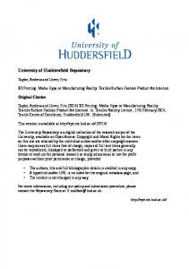
2. Research Methodology 2.1 The Suggested Geometry of the Model The model chosen consists of a double storey complex designed for residential purposes. The spatial layout of the model was designed to maximize space without sacrificing practical functionality in daily use. The sizing of each living space was designed in accordance with NSW Design Standards (2014) guidelines. The layout plan features 2 bedrooms, 2 bathrooms, 1 kitchen, 2 living rooms and a dining room; the floor space totals 108m2 ( See Figure 1)
FIGURE 1. A 3D rendering of the designed structure. The roof the double storey component has provisions/space for solar paneling installation.
The floor plan of the structure consists of 2 storeys totalling 108m2. The structure is individually fabricated into 2 sections. The single storey structure encases the 2nd bedroom, ½ the kitchen and main toilet/bathroom. The double storey structure encases the 2 main living rooms, ½ the kitchen, dining room and master bedroom. An internal staircase is situated in the middle of the structure and is installed post construction.
http://3dcpconference.com/ Email:
[email protected];
[email protected]
1st International Conference on 3D Construction Printing
2
2.1 Numerical Strategy Finite element software Strand 7 is used for the numerical analysis of this structure. The overall structure is consisted of multiple arch roofs for which there are triangular void within those arches. They form a truss-like structure within those arch roofs to take advantage of the transfer of loads within a truss structure and reduce self-weight. Smaller size triangles voids were used at the end of the structure to provide greater strength while reducing the possibility of buckling. The Mesh created below for this project consists of a series of Quad4 Plate elements designed to form the cross section of the structure. The cross section of the 3D Printed structure was created in Strand7 without the aid of AutoCAD. The material properties of the plate elements used was Fiber Reinforced Concrete to provide relevance for the purpose of comparison with the Reference Project. Figure 2 was dictated by the testing parameters of this numerical analysis as well as constructability using the 3D printing technique.
Figure 2. A typical Finite Element Model
The stability and thermal resistance of the structure determined the shape and composition of the internal elements. The final model consists of an internal and external wall separated by a truss like design, this scheme encompassed the internal components (walls, slabs and roof) spanning in one direction (See Figure 3).
Figure 3. The Typical Strand7 Models, including the geometrical truss design and central column
3
[Numerically Modelling and Designing of 3D Printing Structural Elements, Tahmasebinia “et. Al.”]
Additionally, an internal shear wall was implemented in the center span of the slab to improve lateral stability and reduce the maximum tensile stress (on the underside of the central span) induced by permanent and imposed actions. This triangulated truss (composed of FRC) provided stability against lateral and horizontal loads by effectively distributing and transferring loads through the structure. Moreover, this helped to reduced self weight of the slabs without sacrificing tensile/compressive capacities, which in turn allowed the implementation of a greater horizontal truss span. Another important benefit of the truss design is its efficiency in resisting thermal conductivity. This layout of internal and external walls separated by truss work has been shown to reduce the conductance of heat from outside sources by limiting thermal bridges transferring heat (Gosselin et al, 2016). Moreover, this design increases the air pockets within the wall which helps increase thermal resistance (dos Santos and Mendes 2009).The material selected here is based on the strength and constructability requirements of the 3D printing technique. Recycled High Density Polyethylene concrete, rHDPE, or fiber reinforced concrete is selected as an alternative to reinforced concrete. One of the limitations of the 3D printing device is its incapability to incorporate steel bars in its design. There have been advancements in incorporating steel RC in 3D printers, but it is time consuming and increases construction cost. Thus, to overcome the low concrete tensile strength rHDPE is used. Another limitation is the maximum particle size suitable for the 3D printer nozzle, 20mm. Previous research undertaken by Ninoslav et al. (2016), compares and summarizes the properties of plain cement concrete with different grades of rHDPE concrete (Table 1). Table 1. Summary of rHDPE concrete mix (Ninoslav et al., 2016) Concrete Property
Plain
Ø 0.25 mm fibres
C1
C2
C3
C4
𝑬𝒄 (Elastic Modulus)
24.2
24.5
24.9
25.2
33.2
34.3
31.1
32.3
𝒇𝒄𝒕(𝒄𝒚𝒍)-Tensile Strengths
2.79
3.08
2.95
2.96
𝒇𝐜𝐤 (𝒄𝒖𝒃𝒆) -Compressive Strengths
The dead/permanent load of the structure includes the slab and column self weight, additional partitions, staircase weight and the implementation of a solar panel system on the non-habitable roof of the 2 storey structure. These dead loads were calculated by means of accurately modelling the intended 3D printed structure and applying a downward acting gravitational force. The density of the Fiber reinforced concrete mix was taken as 2380 kg/m3 as outlined by Pesic et al. (2016). The live load includes imposed actions set as standards for various residential living spaces as outlined in AS1170. These loads were applied as normal pressure to the brick elements comprising the floor slab of the structure. The wind load transferred to base, assumed constant along structure depth (as h < 25m) (kN/m). The Wind actions applied to the windward and leeward walls were calculated according to AS1170.2. Considering the house is located in Hornsby, NSW, the region is A2 with Terrain category 3. The wind velocity for the region A2 is 45m/s, and the design velocity after considering the location,
1st International Conference on 3D Construction Printing
4
cardinal direction, i.e. SE and structural dimensions, is calculated as 35.48 m/s. Other parameters are calculated based on the AS1170.2. 3. Results and discussions 3.1 The Stability Analysis The stability of this structure was analyzed using a 3-dimensional rendering of the concept design on Strand7. This model was subjected to Permanent, Imposed and Wind actions in accordance with AS1170 requirements to viably predict stability. The loads detailed in previous section of this report were applied to the brick elements as face pressure loads. Permanent Action was modelled using a downward acting gravitational force of magnitude 9.81m/s2 acting on every brick element in the model. Additional permanent actions in this model are provided by partition walls (made of timber or cold formed steel) and the staircase, which are installed after 3D printing has been completed and the structure is installed in its final location. Hence, an additional vertical downward pressure of 0.5 kPa (Clause 2.3 AS1170.2) was also applied to relevant floor brick elements for partitions, while the staircase was modelled as 2kPa of face pressure. Moreover, permanent action was applied to the roof of the double storey model to account for the possible installation of Solar Panels. Similarly, imposed actions were applied to the relevant vertical face of brick elements Relevant imposed actions (detailed in Table 3) were applied to floor brick elements within the dedicated area as outlined in the Floor Plans, not including area dedicated to partition walls. Moreover, imposed loads were applied to the roof the single storey model to account for the possibility of using the space as a balcony/entertainment area). Lastly, Wind actions were also applied as face pressures on the relevant horizontal face of brick elements. This load case included windward wall pressure directed toward the wall/brick faces, leeward wall pressure directed away from the wall/brick faces and roof pressures applied vertically downward. A summary of the finite element model results is detailed by Table 2. Table 2. A summary of the Finite Element Analysis Double Storey Model
Permanent Action (G)
Max. DX Dis placement (m)
4.45 x 10
Max. DY Displacement m)
Imposed Action (Q)
-3
3.81 x 10
-1.34 x 10
-3
Max. Tensile Stress (MPa) Max. Compressive Stress (MPa)
Wind Action (Wu)
-3
1.29 x 10
-7
-1.17 x 10
-3
-1.24 x 10
1.03 (Y)
0.66 (X)
0.191 (Y)
2.32 (Y)
0.90 (Y)
0.204 (Y)
-8
Fiber Reinforced Concrete was identified early in the design stage of this project to be poor in Tensile Strength (relative to its Compressive strength) which is characteristic of nominal concrete structures. Studies into rHDPE Concrete show that the introduction of fiber reinforcement into the concrete mix improves the tensile strength from 1.6 MPa to 3.08 MPa while compressive strength of 32 MPa
5
[Numerically Modelling and Designing of 3D Printing Structural Elements, Tahmasebinia “et. Al.”]
concrete increases to 34 MPa. Using this as a guideline, it can be deduced from the table above that both structures can facilitate these load cases. 𝑀𝑎𝑥𝑖𝑚𝑢𝑚 𝑇𝑒𝑛𝑠𝑖𝑙𝑒 𝑆𝑡𝑟𝑒𝑠𝑠 𝑖𝑛𝑑𝑢𝑐𝑒𝑑 (𝑓𝑡𝑖 ) = 1.03 𝑀𝑃𝑎 < 𝑇𝑒𝑛𝑠𝑖𝑙𝑒 𝑆𝑡𝑟𝑒𝑛𝑔𝑡ℎ (𝑓𝑡𝑢 ) = 3.08 𝑀𝑃𝑎
(1)
3.1 The Thermal Analysis The thermal analysis of this structure aims to predict the heat transfer generated by 3D Printed houses to ensure that it satisfied minimum thermal requirements. This structure is assumed to be in Hornsby, Australia; a humid, subtropical location that has recently been subjected to heat-waves. Hence, it was deemed necessary for this structure to be insulative to external heat sources to provide a comfortable ambient temperature for its inhabitants. This project will focus on steady state heat analysis of the worst case scenario under worst case conditions to appropriately assess its thermal performance. A valuable starting point for thermal performance assessment can be made using the Thermal Resistivity (R-Factor): 𝑅=
𝑡
(2)
𝐾
The thermal properties of rHDPE Concrete is carried over from the reference project. This material has a specific heat of 880 J/kg/K and thermal conductivity of 1.37 W/m/K. This analysis will focus on the external walls and roof (including the truss work) and its ability to dissipate heat as it transfers through the wall and into the house. As stated previously, studies have shown that this geometry has a multipurpose optimization that not only contributes to structural stability but also thermal insulation (Gosselin et al. 2016). 1𝑚 𝑡ℎ𝑖𝑐𝑘 𝐹𝑅𝐶 𝑊𝑎𝑙𝑙: 𝑅 =
𝑡
𝐾
=
1𝑚 𝑡ℎ𝑖𝑐𝑘 𝑇𝑖𝑚𝑏𝑒𝑟 𝑊𝑎𝑙𝑙: 𝑅 =
𝑡
1
1.37
𝐾
=
= 0.73 1
0.22
= 2.78
(3) (4)
It is necessary to understand that higher R factors imply a material is a good insulator. For comparison, other construction material R factors are: 220𝑚𝑚 𝑡ℎ𝑖𝑐𝑘, 𝑈𝑛𝑖𝑛𝑠𝑢𝑙𝑎𝑡𝑒𝑑 𝑆𝑜𝑙𝑖𝑑 𝐵𝑟𝑖𝑐𝑘: 𝑅 =
0.22 1.2
= 0.18
𝐼𝑛𝑠𝑢𝑙𝑎𝑡𝑒𝑑 (𝑤𝑖𝑡ℎ 𝑓𝑜𝑖𝑙 𝑝𝑜𝑙𝑦𝑖𝑠𝑜𝑐𝑦𝑎𝑛𝑢𝑟𝑎𝑡𝑒 ) 𝑆𝑜𝑙𝑖𝑑 𝐵𝑟𝑖𝑐𝑘: 𝑅 = 0.18 +
0.08
0.022
= 3.82
(5) (6)
By inspecting the geometry of the model adopted in this report, heat can be expected to travel through the truss on 2 ways. Hence, 2 R values can be produced (taking the minimum to be conservative).
𝐻𝑒𝑎𝑡 𝑇𝑟𝑎𝑛𝑠𝑓𝑒𝑟 𝑡ℎ𝑟𝑜𝑢𝑔ℎ 𝐴𝑖𝑟 𝑏𝑒𝑡𝑤𝑒𝑒𝑛 𝑊𝑎𝑙𝑙𝑠 : 𝑅 =
0.09
1.37
+
0.27 0.02
+
0.09
1.37
= 13.63
(7)
A better comparison of R values can be made by fixing Δt to compare different wall compositions for thermal insulation performance (Table 3).
1st International Conference on 3D Construction Printing
6
Table 3. Thermal Resistivity Comparison Thermal Conductivity (K)
Thermal Resistivity (R)
Air
0.02
50
Solid Timber
0.22
2.773
Solid FRC Wall
1.37
0.73
1.2
0.833
0.121
8.25
0.04
25
Material Type (Δt=1m)
Uninsulated Masonry Wall Insulated Masonry Wall Fiber Glass Insulation FRC Truss (Averaged)
Wall
1.37
By comparison, the majority of the insulation efficiency of the truss wall stems from the air pockets between its internal and external wall leaf. Despite the fiber reinforced concrete having a relatively high thermal conductivity, the specific design of the project is shown to increase the thermal resistivity of the wall (similar to other wall construction materials). Given the method of calculating the R factor (as seen above) only accounts for the conductivity of the material (not convection or radiation), it is better to evaluate the effectiveness of the walls in dissipating heat with thermal transmittance or U factor. In order to find the U factor, a Steady State Heat analysis was undertaken to determine the heat flux and temperature changes pertinent to design. The model was subjected to worst case scenarios as a conservative approach to assessing thermal performance. According to the Australian Bureau of Meteorology (BOM), the suburb of Hornsby experienced a maximum temperature of 42.7 ̊ Celsius (273.15 + 42.7 = 315.85 K) in the last 2 years. This temperature (taken as a worst case scenario) was applied as Ambient Convection to the outside face of the brick elements of the external walls and roof as well as the plate elements on both open ends of the structure. Conversely, the internal summer temperature of the house was assumed as 23 ̊ Celsius (296.15 K), also applied as ambient convection. Additionally, Solar radiation of 200 W/m3 was also applied as a heat source to the roof only of the structure. Lastly, a forced convection (due to wind gusts) of 170 J/sm2K was applied to the external brick elements with natural convection of 12 J/sm2K to the internal brick elements. The resulting model was generated using Steady State Head Analysis (Figure 4).
Figure 1. Steady State Analysis of the model under the conditions stated above
7
[Numerically Modelling and Designing of 3D Printing Structural Elements, Tahmasebinia “et. Al.”]
The temperature contour above shows how maximum temperatures experienced outside the house can effectively dissipate between the external and internal walls. This geometrical design is able to maintain a relatively stable internal temperature, without much fluctuation within the structure. Plotting the temperature along a single truss element between the walls shows how the truss maximizes its length to dissipate heat. This temperature initially receives a large drop before gradually reducing as it transfers through the conducting material. This initially larger drop from 315.85K to 302.6K (i.e. 42.7 ̊ C to 29.45 ̊ C) may be the transfer of heat between the external wall and the truss where the thermal bridges have the largest area. Increasing the thickness of a solid wall will improve the R factor and contribute to thermal insulation however impractical. This truss geometry limits the thermal bridges available for heat transfer to the truss members, and increases the required heat transfer distance of a 0.45m thick wall to 0.61m. Additionally, the truss members are surrounded by air voids that are much more thermally insulative with a thermal conductance of 0.026-0.028 even in high ambient temperature. This geometry maximizes thermal insulation efficiency while minimizing cost and material use. As a result the internal face temperature of the brick elements only increased by approximately 0.29˚C.
Figure 5. Steady State Heat analysis revealing Temperature contour plot (left) and Heat flux contour plot (right). These contour plots effectively convey the heat dissipating as it conducts through the FRC composite trusses.
Another possible concern surrounding thermal performance is the openings of this structure. Window openings on the side walls of the structure as well as the 4 large openings (2 on each end) at the ends of the structure may be susceptible to higher heat transmittance than the FRC Side walls. The heat flux through these regions may be significantly higher due to higher U factors generally associated with single or double pane glass of approximately 1.6 W/m2K (Aste et al, 2009). Due to the nature of the window opening, truss elements joining the external and internal members were different than the rest of the structure. Top and bottom flat truss members were implemented (as can be seen in Fig. 14). This results in a different heat dissipation behavior as can be seen in Graph 2 above. Moreover, the heat transfer distance is no longer angled and can only dissipate through 0.45m of rHDPE Concrete. However, steady state heat analysis shows that this has minimal effect on
1st International Conference on 3D Construction Printing
8
the increase in wall temperature as only an additional temperature increase of 0.23˚ C and an overall temperature increase of 0.52˚ C. 4. Conclusions The 3D printing construction technology is still in its incubation period and it requires a lot of thought process and advance detailing. In order to implement it in bulk, system needs to be upgraded and constant learning process is required. The model designed in this project satisfies its initial aim, which was to assess a residential structure intended for mass production and distribution. The layout is adopted from a 2 storeyed house constructed with 3D printer in Shanghai, China. rHDPE concrete (FRC) has been shown to consistently improve nominal strength capacities of the structure material. This FRC composite has been shown through finite element modelling to satisfy load capacities in accordance with Australian Standards. The material and geometrical design is effective in providing the required tensile strength to the concrete without sacrificing compressive strength. From results of finite element analysis in Strand7, it can be concluded that this is a viable method of construction in terms of stability and thermal comfort. Steady state heat analysis of the structure reveals that the maximum change temperature of the internal wall is ∆𝑇 = 0.52°𝐶. Hence, it can be concluded that the increase in wall temperature due to heat transfer does not have significant impact in increasing internal ambient temperature. The geometrical composition of the exterior of the structure (truss framework) assists in creating passive insulation against heat ingress, evident through analysis of U and R factors. References 1. 2. 3.
4.
AS-1170.2, Australian Standard SAA loading code Part 2, Wind Actions. AS1170. 11989, Standards Association of Australia, Sydney (1989). AS 1170.1, SAA Loading Code—Part 1: Dead and Live Loads and Load Combinations, AS1170. 1-1989, Standards Association of Australia, Sydney (1989). Aste, N., Angelotti, A. and B uzzetti, M., 2009. The influence of the external walls thermal inertia on the energy performance of well insulated buildings. Energy and buildings, 41(11), pp.1181-1187. Building Sustainability Index (2013). BAS IX thermal comfort protocol. In: Building Sustainability Index, Department of Planning and Environemnt, Sydney, New South Wales
5.
Design Standards (2014). Revision 1. In: NSW Land and Housing Corporation, Sydney, New South Wales.
6.
Gosselin, C., Duballet, R., Roux, P., Gaudillière, N., Dirrenberger, J. and Morel, P., 2016. Large-scale 3D printing of ult ra-high performance concrete–a new processing route for architects and builders. Mat erials & Design, 100, pp.102-109.
Pešić, N., Živanović, S., Garcia, R. and Papastergiou, P., 2016. Mechanical properties of concrete reinforced with recycled HDPE plastic fibres. Construction and Building Materials, 115, pp.362-370. 8. Dos S antos, G. H. and Mendes, N., 2009. Combined heat, air and moisture (HAM) transfer model for porous building materials. journal of building physics, 32(3), pp.203-220. 9. dos Santos, G.H. and Mendes, N., 2004. Analysis of numerical methods and simulation time step effects on the prediction of building thermal performance. Applied Thermal Engineering, 24(8-9), pp.1129-1142. 10. NSW Bureau of Meteorology. 2018. Daily maximum temperature. [ONLINE] A vailable at: http://www.bom.gov.au/jsp/ncc/cdio/weatherData/ av?p_nccObsCode=122&p_display_type=d ailyDataFile&p_startYear=&p_c=&p_stn_num= 066124. [Accessed 8 June 2018].
7.