3D Shape Restoration via Matrix Recovery Min Lu1 , Bo Zheng1 , Jun Takamatsu2 , Ko Nishino3 , and Katsushi Ikeuchi1 1
3
Institute of Industrial Science, The University of Tokyo, Tokyo, Japan {lumin, zheng, katsu}@cvl.iis.u-tokyo.ac.jp 2 Nara Institute of Science and Technology, Nara, Japan
[email protected] Department of Computer Science, Drexel University, Philadelphia, USA
[email protected]
Abstract. Cultural relics are often damaged and incomplete due to various reasons. For the purpose of helping archaeological studies, we present a novel method for simultaneously restoring the original shapes of a group of similar objects. Based on the assumption that similar shapes are approximately linearly correlated, we use a matrix recovery technique to achieve the restoration. In order to represent input shapes in a matrix form, vectorization of each aligned sample is carried out by stacking coordinates of dense corresponding points that are generated by a surface matching scheme using non-rigid deformation. An experiment using 3D scans of facial sculptures from Bayon is conducted, and the result verifies the feasibility and effectiveness of our method.
1
Introduction
Three-dimensional digital replicas play an increasingly important role in cultural heritage preservation. With current 3D data acquisition technology, such as laser rangefinders, the geometric information of real-world objects can be accurately and reliably digitized. These 3D digital models can then be used for various archaeological studies. For example, a 3D shape comparison technique was used to help archaeologists understand the meaning of four-faced towers in the temple Bayon at Angkor [1]. Due to natural and human factors, e.g., weathering and vandalism, historic cultural relics are often partially damaged (as an example see Figure 2b). Even for complete objects, sometimes it is difficult to acquire all the shape information, because of self-occlusion or some special physical properties of the surface. Therefore, 3D shape completion or restoration becomes a problem of practical significance. Several approaches have been proposed for 3D shape restoration. For instance, one may focus on the smoothness of the underlying surface, using localized geometric constraints to achieve a smooth continuation [2–4]. This kind of completion methods is suitable for filling holes, but when the missing part contains a lot of details and structural information, it will become ineffective. An alternative approach is to use a copy and paste scheme. Patches with similar
2
M. Lu et al.
v1
Low-rank matrix recovery
...
...
Dense correspondences via surface matching
...
...
v2
vn input models
dense corresponding points
Vectorization restored output
Fig. 1: An overview of our shape restoration pipeline. For the input shapes, we first generate dense correspondences among them; then, by stacking coordinates of these corresponding points, input samples are represented as fixed-length vectors; in the end, the restoration process is accomplished by a matrix recovery procedure.
surface characteristics could be selected from either the incomplete object itself [5, 6], or analogous candidate models [7, 8]. In this paper, we focus on a specific instance of the shape recovery problem: given a group of similar objects, where many of them are partially damaged and incomplete, we aim to restore all these objects simultaneously, using the common shape structures. Notice that this specific problem setting is not so unusual in heritage conservation. For example, there are usually many similar god statues excavated from the same place, keeping a unified style. We present a new shape restoration method based on a matrix recovery method [9]. We formulate the shape restoration task as a low-rank matrix recovery problem, that we solve using convex optimization. A simple but effective dense correspondence scheme for shape vectorization is also proposed, where a deformation-based surface matching method is used. Figure 1 depicts an overview of our proposed method. Given a group of similar shapes, we first generate dense correspondences among all samples. Then each sample is represented as a fixed-length vector, using coordinates of corresponding points. Finally, input samples are restored to their original shapes using matrix recovery. The remainder of this paper is organized as follows: Section 2 first gives a brief introduction of matrix recovery theory, and then formulates the task of restoring a group of similar shapes as a low-rank matrix recovery problem; Section 3 introduces the procedure of acquiring dense correspondences among all input samples, which is a crucial step for shape vectorization; Section 4 presents results of an experiment using real world relics, demonstrating the effectiveness of the proposed method; and Section 5 concludes with a discussion of the limitations and promising directions of our method.
3D Shape Restoration via Matrix Recovery
2
3
Low-Rank Matrix Recovery
Matrix recovery, also known as robust principal component analysis (Robust PCA), was first introduced in [9]. The essential idea of this theory is to recover corrupted entries of a matrix using structural information of the matrix itself. Compared to ordinary principal component analysis, this method is more robust to outlying and corrupted observations, and it can handle such complex problems as background modeling [10] and batch image alignment [11]. In this section, we first give a brief introduction of matrix recovery theory, and then we explain how this method is used to solve our shape restoration problem. 2.1
Problem Statement
Given the observed data matrix D ∈ Rm×n , generated by corrupting some of the entries of an unknown low-rank matrix A ∈ Rm×n , let an error matrix E ∈ Rm×n represent the corruption. E is also unknown but supposed to be sparse. The goal is to recover A. Robust principal component analysis [9] solves this problem by seeking the lowest rank A that could have generated the observation D, while subjecting the error matrix E to a sparseness constraint: kEk0 6 k. Here the L0 norm is employed to measure the matrix sparseness. Thus the initial problem becomes an optimization: min A,E
rank(A) + γkEk0 ,
s.t.
A + E = D,
(1)
where γ is the weighting parameter that trades off the rank of the solution and the sparseness of the error. As detailed in [9], the optimization problem (1) is highly non-convex, and currently with no efficient solution. A tractable optimization, however, can be obtained by relaxing the original problem. By replacing the L0 norm with the L1 norm, and by measuring the rank with the nuclear norm kAk∗ , problem (1) can be converted to a tractable convex optimization: min kAk∗ + λkEk1 . A,E
s.t.
A + E = D.
(2)
Here theP nuclear norm of a matrix is defined as the sum of its singular √ values: . kAk∗ = i σi (A). And the weighting parameter λ is in the form c/ m, where c is a constant, and typically set to be around 1. Notice that the new objective function in problem (2) is continuous and convex, so it can be solved efficiently [9, 12]. 2.2
Applying to The Shape Restoration Problem
Now let us describe how we formulate our shape restoration problem as matrix recovery. Given an object category C, in which many samples are partially damaged and incomplete, let {si }ni=1 denote a group of observed 3D shape and
4
M. Lu et al.
{s0i }ni=1 denote the corresponding original shapes without corruption. As we assume that all these samples are of similar shapes and structures, i.e. they are drawn from the same category, we may assume that they belong to a same linear subspace S. In other words, as long as n is sufficiently large, an arbitrary sample s0 from the same category C will approximately lie in the linear span of the samples {s0i }ni=1 : n X s0 ≈ αi s0i , (3) i=1
where {αi }ni=1 ∈ R are coefficients. In our method, this assumption of linear correlation is the only prior knowledge we rely on to restore the corrupted samples. As in [11], we define an operator vec : C → Rm that extracts an mdimensional feature vector from a 3D model si . In our shape restoration case, this operation can be accomplished by simply stacking the (x, y, z) coordinates of the points of interest. We will discuss how to achieve this via non-rigid registration in Section 3. This results in a matrix A that represents all the observed samples: . A = [vec(s01 )| · · · |vec(s0n )] ∈ Rm×n . (4) According to the linear correlation assumption (Eq. (3)), matrix A should be approximately low-rank. For an observation sample si , let ei denote the corrupted or missing component from the original shape s0i , so si = s0i + ei . Using the operator vec we defined above, the corrupted observation can then be written as . D = [vec(s1 )| · · · |vec(sn )] = A + E, (5) where matrix A is a low-rank matrix defined in Eq. (4), revealing the common . shape information of this category, and E = [vec(e1 )| · · · |vec(en )] ∈ Rm×n is the error matrix, representing the shape corruption. As we assume that the corruption is partial and localized, the error matrix E should be sparse, which means most of its entries are zero. Thus, the task of restoring the shape of similar objects in the same category becomes a matrix recovery problem as defined in Section 2.1.
3
Shape Correspondence and Vectorization
In the whole process of shape restoration via matrix recovery, a crucial step is to properly represent the shape of each sample using a fixed-length vector, so that accurate correspondences are established among all input objects. Recall that in Section 2.2, we introduced an operator vec to extract an m-dimensional feature vector from a 3D shape. In this section, we describe this procedure in detail. 3.1
Sparse Correspondences
First, let us consider establishing a group of sparse corresponding points. Obviously, a trivial solution is to manually specify the corresponding points. Although
3D Shape Restoration via Matrix Recovery
5
there are several automatic methods [13–16], using human assistance is still the most reliable approach for finding correspondences, especially when data corruption and high scanning noise exist, which is common for historical objects in the outdoors. If the output correspondence is acceptable, automatic shape registration methods could be chosen as well. Notice that the methods in [15, 16] can also be used to generate dense correspondences. In our work, we chose to leverage manual intervention. Among all input shapes, a relatively complete sample is chosen as a template (Figure 2a). We predetermine a group of feature points (Figure 2c) and manually select these points on each sample (Figure 2d). If certain points are missing due to shape corruption, we simply mark them as null points. Then we adopt a rigid registration process for all samples (Figure 2f). The posture of the template is fixed, and all other samples are aligned to the template using Iterative closest point (ICP) [17] algorithm. Note that the initial posture estimation could be calculated from the sparse corresponding points. 3.2
Dense Correspondences and Vectorization
Based on the sparse correspondences, a sampling strategy while keeping the correct correspondence could be carried out to obtain dense correspondences among all input samples. The uniform remeshing method in [18] is a workable choice, but here we use a surface matching scheme based on shape deformation: 1. Adopt a uniform sampling on the template sample to create a final template with an adequate number of points (Figure 2g). 2. Deform the final template to fit each sample using the sparse correspondences we manually selected before as control handles for the non-rigid surface deformation process. 3. Search the closest point on the destination sample for each point of the final template, and label the result as the approximate corresponding point. Here we set a distance threshold: if there is no point within this threshold, correspondence is marked as a null point. For the shape deformation phase, a moving least squares (MLS) deformation similar to [19] is employed: Given a set of N control points (in our case the corresponding points), 3 let {pi }N i=1 ∈ R be the original positions on source model S0 , and N 3 {qi }i=1 ∈ R be the corresponding deformed positions on destination shape Sd . Consider an arbitrary point x ∈ R3 on the source model S0 , let Fx denote the transformation that gives the corresponding position of point x on Sd after the deformation. According to the MLS theory, Fx could be determined by solving an optimization: min Fx
N X i=1
1 kFx (pi ) − qi k2 , d(x, pi )2α
(6)
where d(x, pi ) is the distance between x and pi , α is a system parameter.
6
M. Lu et al.
(a)
template sample
(b)
(e)
cropped template
(f)
a damaged sample
rigid registration
(c)
(g)
selected point set
points on template
(d)
manual labeling
(h) corresponding points
Fig. 2: Establishing dense correspondences. (a) and (b) are two illustrations of input shapes, where (a) is relatively complete and selected as the template, while (b) is a heavily damaged sample; (c) shows the point set chosen for sparse correspondences and (d) is an example of manually labeled points; (e) is a cropped template sample that keeps the region of interest only; (f) shows the rigid registration procedure between the template and other samples before shape vectorization; (g) shows selected points on the template via uniform sampling, and (h) is the corresponding points on example (b).
In order to get better deformation results, geodesic distances are used in the weight function. Given one 3D shape represented by a triangle mesh, the geodesic distance between two points on its surface can be approximated with the length of the shortest path from one to the other, which can be calculated by Dijkstra’s algorithm. Moreover, the mapping Fx is assumed to be an affine transformation, consisting of a linear transformation M followed by a translation T : Fx (x) = Mx + T. So far, we have obtained a set of dense sampling points with correct correspondences for all input samples. As for the vectorization of each sample, the (x, y, z) coordinates of all selected points are stacked to form a vector that represents the 3D shape. Obviously, all these vectors are of the same length as the number of sampling points are fixed. Notice that points corresponding to damaged parts may be marked as null points in our scheme. These null points could
3D Shape Restoration via Matrix Recovery
7
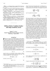
Fig. 3: Some example 3D shapes from the 3D database of facial sculptures in Bayon
be substituted with nearby points on the object’s convex hull or bounding box for actual calculation. Figure 2h shows an example where points corresponding to the missing right side of face are chosen from the bounding box instead.
4
Experimental Results
We conducted experiments to restore the 3D shapes of real-world cultural relics to validate the proposed method. A group of 151 scanned models of facial sculptures in the temple Bayon (Figure 3) were used. Due to weathering, vandalism, and some other reasons, many sculptures are incomplete, and some of them are damaged so heavily that only a small part is preserved (e.g. Figure 2b). Each sample contains around 500,000 points and 1,000,000 triangles in average. A relatively complete sample, No. 15N (Figure 2a), is chosen as the template and 13 feature points (apex of nose, corners of eyes and mouth, etc.) for sparse correspondences were chosen (Figure 2c). These feature points were manually localized on each sample. Compared to the outer part of a facial sculpture, such as the ears and the headwear, the inner part (the face) contains more information we are interested in. Taking this into consideration, before generating dense correspondences, the outer part of the template is masked out (Figure 2e). In the dense correspondence phase, all samples were downsampled to 10,000 points, which makes the observation matrix D 30,000 rows and 151 columns. The Augmented Lagrange Multiplier (ALM) method [12] is employed to solve the convex optimization problem (2). On a common PC platform, the processing time for solving Eq. (2) was within a few minutes. Figure 4 shows two restoration examples. Sample No. 4E is so severely damaged that it is difficult to identify facial features, while the situation of sample No. 24S is even worse: several parts, including the whole forehead and half the nose, are missing. In spite of that, our restoration method still gives satisfactory restoration results.
8
M. Lu et al.
(a)
sample No. 4E
(b)
sample No. 24S
Fig. 4: Two restoration results with parameter c set to 1. In each group, the picture on the left side shows the observed geometry, and the other one shows the restored √ output. Parameter c is a scaled version of parameter λ in Eq. (2): λ = c/ m, where m is the length of the input vectors.
In the convex optimization process (Eq. (2)), there is a weighting parameter λ that trades off the rank of the solution versus √ the sparseness of the error. As we mentioned, parameter λ is in the form c/ m, where c is a constant, typically set to 1. m is the length of the input vectors, fixed to three times the number of corresponding points in our experiment. Therefore the constant c could be used as a scaled version of the parameter λ. Notice that for our shape restoration problem, this parameter c trades off the similarities of all input models versus the characteristics of each sample: the larger c is, the more individual characteristics, as well as the error caused by shape incompletion, will be kept and vice versa. Figure 5 illustrates the effect of changing the value of parameter c. The result shows that the typical value 1 seems to be a good trade-off for parameter c in our shape restoration task.
5
Conclusion and Discussion
We have proposed a novel method for 3D shape restoration. We focused on a group of similar shapes, aiming to restore them simultaneously. The key idea is to make use of shape similarities, which is handled by a matrix recovery procedure. Experimental results on facial sculptures from Bayon verify the effectiveness of our method. Although it is difficult to evaluate the accuracy of our restoration output, as there is no ground truth available, we believe the method is of significant importance for meaningful and feasible archaeological studies, especially when the shapes of a group of similar relics are needed to be restored. The method, as it currently stands, has a few limitations. First, the scheme for acquiring dense shape correspondences is inefficient. Currently we use the closest point after shape deformation as an approximation of the correspondence, which is not guaranteed to be accurate and reliable, especially when significant nonrigid deformation exists. The choice of the template sample may also affect the result. Second, some shape details are lost after restoration. This is caused by
3D Shape Restoration via Matrix Recovery
(a)
No. 19E
(b)
No. 20E
(c)
No. 22E
(d)
No. 22N
(e)
9
No. 24E
Fig. 5: Five different restoration results, with three different values of parameter c. Each column belongs to the same sample, and the first row shows the original inputs. The remaining rows demonstrate the outputs under different values of parameter c, 2, 1.6 and 1, respectively, from top to bottom.
the downsampling process and the parameter selection in matrix recovery. As an immediate future work, we plan to investigate methods to distinguish corrupted and missing data so that different strategies can be employed to restore each.
References 1. Kamakura, M., Oishi, T., Takamatsu, J., Ikeuchi, K.: Classification of Bayon faces using 3D models. In: The 11th International Conference on Virtual Systems and Multimedia (VSMM 2005). (2005) 2. Chalmoviansk´ y, P., J¨ uttler, B.: Filling holes in point clouds. In: Mathematics of Surfaces, LNCS 2768. Springer-Verlag (2003) 3. Ju, T.: Robust repair of polygonal models. ACM Trans. Graph. 23 (2004) 888–895 4. Nooruddin, F.S., Turk, G.: Simplification and repair of polygonal models using volumetric techniques. IEEE Transactions on Visualization and Computer Graphics 9 (2003) 191–205 5. Sharf, A., Alexa, M., Cohen-Or, D.: Context-based surface completion. In: ACM SIGGRAPH 2004. (2004)
10
M. Lu et al.
6. Breckon, T.P., Fisher, R.B.: Three-dimensional surface relief completion via nonparametric techniques. IEEE Transactions on Pattern Analysis and Machine Intelligence 30 (2008) 2249–2255 7. Pauly, M., Mitra, N.J., Giesen, J., Gross, M., Guibas, L.J.: Example-based 3D scan completion. In: SGP ’05: Proceedings of the third Eurographics symposium on Geometry processing. (2005) 8. Kraevoy, V., Sheffer, A.: Template-based mesh completion. In: SGP ’05: Proceedings of the third Eurographics symposium on Geometry processing. (2005) 9. Wright, J., Ganesh, A., Rao, S., Peng, Y., Ma, Y.: Robust principal component analysis: Exact recovery of corrupted low-rank matrices via convex optimization. In: Advances in Neural Information Processing Systems 22. MIT Press (2009) 10. Cand`es, E.J., Li, X., Ma, Y., Wright, J.: Robust principal component analysis? submitted to Journal of the ACM (2009) 11. Peng, Y., Ganesh, A., Wright, J., Xu, W., Ma, Y.: RASL: Robust alignment by sparse and low-rank decomposition for linearly correlated images. In: Proc. IEEE Conf. on Computer Vision and Pattern Recognition (CVPR). (2010) 12. Lin, Z., Chen, M., Wu, L., Ma, Y.: The augmented lagrange multiplier method for exact recovery of corrupted low-rank matrices. submitted to Mathematical Programming (2009) 13. Zhang, H., Sheffer, A., Cohen-Or, D., Zhou, Q., van Kaick, O., Tagliasacchi, A.: Deformation-driven shape correspondence. Computer Graphics Forum (Special Issue of Symposium on Geometry Processing 2008) 27 (2008) 1431–1439 14. Lipman, Y., Funkhouser, T.: M¨ obius voting for surface correspondence. In: ACM SIGGRAPH 2009. (2009) 15. Zeng, W., Zeng, Y., Wang, Y., Yin, X., Gu, X., Samaras, D.: 3D non-rigid surface matching and registration based on holomorphic differentials. In: ECCV ’08: Proceedings of the 10th European Conference on Computer Vision. (2008) 16. Zeng, Y., Gu, X., Samaras, D., Wang, C., Wang, Y., Paragios, N.: Dense non-rigid surface registration using high-order graph matching. In: Proc. IEEE Conf. on Computer Vision and Pattern Recognition (CVPR). (2010) 17. Besl, P.J., McKay, N.D.: A method for registration of 3-D shapes. IEEE Transactions on Pattern Analysis and Machine Intelligence 14 (1992) 239–256 18. Li, X., Jia, T., Zhang, H.: Expression-insensitive 3D face recognition using sparse representation. In: Proc. IEEE Conf. on Computer Vision and Pattern Recognition (CVPR). (2009) 19. Alvaro, C., Claudio, E., Antonio, O., Paulo, R.C.: 3D as-rigid-as-possible deformations using MLS. In: The 25th Computer Graphics International Conference (CGI’2007). (2007)