3D Spatial Operations in Geo DBMS Environment for 3D GIS Chen Tet-Khuan1, Alias Abdul-Rahman1, and Sisi Zlatanova2 1 Department of Geoinformatic, Faculty of Geoinformation and Engineering, 81310 UTM Skudai, Malaysia {kenchen1, alias1}@fksg.utm.my 2 Section GIS Technology (GISt), OTB Research Institute for Housing, Urban and Mobility Studies, Delft University of Technology, The Netherlands
[email protected]
Abstract. Next generation of GIS software should be able to manipulate and analyse complex situations of real world phenomena. One of the desired components in such software or system is the geometric modeling that works with 3D spatial operations. This paper presents a portion of problem that we currently attempt to solve, that is the 3D spatial operations for Geo DBMS. Some popular spatial operations in 3D GIS for example 3D XOR, 3D union, 3D intersection, and 3D difference are vital for 3D spatial analysis and forms major discussion of this paper and part of our research effort to address the 3D GIS problem. To formulate this research in a suitable way, our approach is to develop the new 3D data type, polyhedron, within geo-DBMS. The basic idea is to relate the implementation of intersection point in 3D planar polygon (Chen and Abdul-Rahman, 2006) into the geometrical modeling for 3D spatial operations. The approach works and we highlighted the results by using the real world data sets. The research shows that the essential mathematical algorithms are applicable for real world objects and provides a solution towards a full 3D analytical operation in future. Keywords: 3D spatial operations, geo-DBMS, and 3D GIS.
1 Introduction There are several aspects need to be addressed in GIS research, one of them is the geometrical modelling for 3D spatial operations in geo-DBMS environment. Common 2D operation tools like polygon overlay, merging and dissolving polygons and lines, or even buffering operation in analytical-based geographic information systems. However, adding the third dimension to 2D GIS, most of the spatial tools become more complicated. The initial problem happens in spatial modeling. Different spatial models deal with different geometrical modeling in solving its spatial O. Gervasi and M. Gavrilova (Eds.): ICCSA 2007, LNCS 4705, Part I, pp. 151–163, 2007. © Springer-Verlag Berlin Heidelberg 2007
152
C. Tet-Khuan, A. Abdul-Rahman, and S. Zlatanova
analytical operations. In literature (3D FDS – Formal Data Structure by Molenaar (1990); TEtrahedral Network – TEN by Pilouk (1996); the 3D TIN-based OO model by Abdul-Rahman (2000); the Simplified Spatial Model - SSS by Zlatanova (2000); the Urban Data Model - UDM by Coors (2003); OO3D by Shi, et al. (2003)), most of the spatial models focus on the object construction and topological relationships. However, geometrical modeling for spatial operation (within geo-DBMS) is rather limited for 3D GIS. In this paper, we concentrate on simple but complete strategy in developing multiple spatial operations for 3D GIS. The paper is organized in the following order: first, short discussion for the 3D objects construction in three-dimension, i.e. polyhedron. Then, the intersection between 3D line and 3D planar polygon is discussed in section 3. This process involves the determination of intersection 0D feature inside/outside the 3D planar polygon, which had been discussed in Chen and Abdul-Rahman (2006). Section 4 describes the bridging as well as the related methodology for the development of the internal and external segments. Section 4 also describes the integration of segments for the multiple spatial operations. The experiment and discussions is presented in section 5 and the research is concluded in section 6.
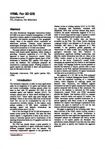
2 Characteristic of Polyhedron In this paper, the spatial object involves in the 3D spatial operations is polyhedron. Polyhedron is a 3D equivalent of a set of polygon that bounds a solid object. It is made up by conectiong all faces, sharing a common edge between two adjacent polygons. The most important constrain is all polygons that make up the polyhedron have to be planar. This means that all points used to construct a polygon must be in the same plane. Fig. 1 denotes a sample of a planar and non-planar polygon. The characteristics of a valid polyhedron should have the following rules (Aguilera & Ayal (1997), Aguilera (1998)): •
Flatness – all polygons that bound a single volume of polyhedron must be flat. This means all vertices involve in constructing a polygon should be in the same plane. The flatness of a polygon can be verified by plane equation as follow: Ax + By + Cz + D
•
=
0
(1)
Polyhedron must be single volume object – a set of polygons that make up a polyhedron should be bounded as a single volume. In order to create a single volume of polyhedron, some rules must be followed: o
Each edge (derived out of 2 vertices) should be shared by only 2 polygons. This rule will result in a simple polyhedron, i.e. outer ring will not touch the boundary of the polyhedron. On the other hand, if an edge is shared by more than 2 polygons, the polyhedron may consist at least 2 volumes.
3D Spatial Operations in Geo DBMS Environment for 3D GIS
153
Fig. 1. (a) Planar polygon, and (b) non-planar polygon
•
Simplicity characteristic – as discussed by Arens (2003). However, this condition could be simplified by enforcing the construction of a polygon as follow: o o
o o o
Each edge has exactly 2 vertices only. The starting and ending points of a polygon is same, and will only be stored once. E.g. a polygon consists 4 points (a, b, c, d), thus the polygon will be stored as (a, b, c, d, a), instead of (a, b, c, d, e), although a = e. Any point(s) with same location will be stored only once. Polygon must have an area. Lines from a polygon must not self-intersecting. Singularity of polyhedron is not allowed, i.e. lower dimension object must not exist in the interior of higher dimension. E.g. point will not exist in the interior of line or polygon or polyhedron, line will not exist in the interior of polygon or polyhedron. However, lower dimension object may exist at the border of higher dimension object. This rule may directly avoid polygon intersects with other polygon(s) (see Fig. 2). Any polygons that intersect with other polygon(s) will not be stored as a part of polyhedron.
Fig. 2. Polygon intersection causes the singularity of points and line
154
C. Tet-Khuan, A. Abdul-Rahman, and S. Zlatanova
3 Line and Solid Object Intersection The 3D spatial operation that involves 2 polyhedrons is the main focus for this paper. As mentioned in the previous section, polyhedron is constructed by a set of faces. The intersection between 2 polyhedrons will directly relate the intersection between line and planar polygon. The first polyhedron is the base object, whereas the second polyhedron becomes the target object in this intersection. The 3D line (from first polyhedron) is the base object, whereas the 3D planar polygon is the target object (see Fig. 3).
Fig. 3. Base and target object
3.1 Plane Equations The intersection between base object (3D line) and target object (3D planar polygon) is initial part of the development of 3D spatial operations. Therefore, the plane equation (from target object) is important in the intersection. In 3D, one can always specify 3 non-collinear points P0=(X0,Y0,Z0), P1=(X1,Y1,Z1), P2=(X2,Y2,Z2) as the vertices of a triangle, the most primitive planar object and it can be defined uniquely the plane satisfying the following equation: X – X0 X1 – X0 X2 – X0
Y – Y0 Y1 – Y0 Y2 – Y0
Z – Z0 Z1 – Z0 Z2 – Z0
0
(2)
Ax + By + Cz + D = 0, with normal, Pn = (A, B, C)
(3)
=
This determinant is satisfying general form of plane equation:
3.2 Intersection of 3D Line and 3D Polygon The plane equations as illustrated in preceeding section will be used in determining the line and polygon intersection. This intersection (i.e. line and polygon) yields a point or a line. Fig. 4 shows the intersection between these two primitives.
3D Spatial Operations in Geo DBMS Environment for 3D GIS
155
Fig. 4. Intersection results: (a) point, and (b) line – 2 points
To compute the intersection point between 3D line and 3D polygon, both line and plane equation are given as follows (see Fig. 4): Y = m1X + c1
(4)
Z = m2X + c2
(5)
where mi = gradient or slope, ci = the y intercept, and i denote an array (1 to n). The intersection between 3D line and 3D polygon may imply an impossible intersection (see Fig. 5).
Fig. 5. Intersection between 3D line and 3D planar polygon
4 Intersection of Base and Target Object Two solid objects intersect each other as shown in Fig. 6. Since a solid object is constructed by a set of faces, and a face is constructed by a series of lines, the intersection that involves 3D line and 3D face is discussed. This is because the intersection result will be used to define internal and external of base object, so as to target object.
156
C. Tet-Khuan, A. Abdul-Rahman, and S. Zlatanova
Fig. 6. Possible intersection between base and target object
For some cases, each base line may intersect many target faces. Thus, the arrangement of intersection points need to be done in a proper manner in order to produce a correct trimmed link (see Fig. 7).
Fig. 7. Multiple intersection points
4.1 Bridging All Related Intersection Points After all intersection points were computed and arranged in proper manner, the related intersection points will be connected as bridge to form a link. This link denotes as the intersection from target solid as a complete intersection toward the base face. The target solid B will be as base object, whereas the solid A will become target object in order to produce intersection points. The intersection points are useless if they are not connected in an appropriate manner. The sequence of each link needs special treatment
Fig. 8. Cross-connected link (view from top)
3D Spatial Operations in Geo DBMS Environment for 3D GIS
157
in order to produce a correct bridge for further applications. The cross-connected faces from the target object will form each link for base object. Fig. 8 denotes the target faces intercept the base face. The internal link needs to be defined as a bridge. 4.2 Internal and External Segments for Base and Target Objects After creating the cross-connected link, it will be used to develop two separated segments, i.e. internal and external for both base and target solid. Therefore, the total of 4 segments will be produced. When a cross-connected link of base object is created, it will be used twice in developing the internal and external segments. Both implementations work in opposite directions (see Fig. 9).
Fig. 9. Opposite direction of same cross-connected link
Each base solid object is constructed by a set of faces. Therefore, the base faces are used to construct the external segment of base solid, whereas the other internal segment (from the same base faces) will be used for target solid. As the base solid is completely modeled, the target object will be dealt as a base solid, and vice-versa. Consequently, the external segment of base solid (previously was the target solid) will be constructed and the internal segment will be implemented in target solid (previously was the base solid, see Fig. 10).
Fig. 10. Internal and external segment (view from top)
158
C. Tet-Khuan, A. Abdul-Rahman, and S. Zlatanova
Fig. 11. The internal & external of base and target solids
The determination of internal and external segments of base and target object, are given in Fig. 11. 4.3 The Internal and External Segments The integration of the internal and external of base and target object can be done in solving multiple 3S spatial analytical solutions. Some of the popular 3D spatial analytical solutions are XOR, DIFFERENCE, INTERSECTION, and UNION (see Fig. 12).
Fig. 12. The approaches for (a) 3D DIFFERENCE, (b) 3D UNION, (c) 3D INTERSECTION, & (d) 3D XOR
5 Experiment and Discussions This work is implemented within PostgreSQL environment. The existing spatial objects available in PostgreSQL are rather limited to 2D (i.e. point, line, and polygon), but not 3D primitive object. Thus, 3D polyhedron will be discussed. The methodology for the complete implementation is given in Fig. 13. Most of the commercial DBMS enable users to create a new user-defined data type and functions. In this research, the user-defined data type and functions are written in C. The user-defined data type must always have input and output functions. These functions determine how the type appears in strings (for input by the user and output to the user) and how the type is organized in the memory. The methodology of
3D Spatial Operations in Geo DBMS Environment for 3D GIS
159
Fig. 13. The implementation of new 3D datatype & operations for DBMS
Fig. 14. Workflow of creating user-defined datatype/function in PostgreSQL
creating user-defined data type and function/operation are presented in the flowchart as follows: (see Fig. 14) The following SQL line denotes a sample of a polyhedron will be defined in PostgreSQL: SELECT * FROM BODYTABLE WHERE PID = 1; 1,POLYHEDRON(PolygonInfo(6,24),SumVertexList(8),SumPolygon List(4,4,4,4,4,4),VertexList(100.0,100.0,100.0,400.0,100. 0,100.0,400.0,400.0,100.0,100.0,400.0,100.0,100.0,100.0,4 00.0,400.0,100.0,400.0,400.0,400.0,400.0,100.0,400.0,400. 0),PolygonList(1,2,6,5,2,3,7,6,3,4,8,7,4,1,5,8,5,6,7,8,1, 4,3,2))
160
C. Tet-Khuan, A. Abdul-Rahman, and S. Zlatanova
1) 2) 3)
PolygonInfo(6,24) denotes 6 polygons and 24 IDs in PolygonList, SumVertexList(8) denotes the total vertices, SumPolygonList(4,4,4,4,4,4) denotes total vertices for each of polygon (total polygon is 6, referred to (1)), VertexList() denotes the list of coordinate-values for all vertices (with no redundant), and PolygonList() denotes the information about each polygon from sets of ID.
4) 5)
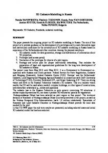
The experiment is tested using the real dataset of a group of buildings. Two block of apartments are selected to be used for the spatial operation as follows (see Fig. 15):
Fig. 15. Two apartments selected from a group of building
The following SQL statement runs the 3D Difference (see Fig. 16a): SELECT GMDIFFERENCE3D(a.POLYHEDRON,b.POLYHEDRON) AS GM_DIFFERENCE3D FROM test a, test b where a.PID=1 and b.PID=2; The result: GM_DIFFERENCE3D --------------------------------------------------------('POLYHEDRON(PolygonInfo(9,42),SumVertexList(14),SumPolyg onList(4,6,6,4,6,4,4,4,4),VertexList(100,100,100,400,100, 100,400,100,400,100,100,400,400,400,100,400,400,300,400,3 00,300,400,300,400,100,400,100,100,400,400,300,400,400,30 0,400,300,300,300,400,300,300,300),PolygonList(1,2,3,4,2, 5,6,7,8,3,5,9,10,11,12,6,9,1,4,10,4,3,8,13,11,10,1,9,5,2, 14,7,8,13,12,14,13,11,14,12,6,7))')
3D Spatial Operations in Geo DBMS Environment for 3D GIS
161
For visualization purposes, ArcGIS’s extension, 3D Analyst is used to verify the result. Although PostGIS provides a function pgsql2shp for export to shape files, it cannot be used since it works only with the natively supported data types of PostGIS. Therefore we have implemented our own function. The integration between PostgreSQL and ArcGIS is beyond the scope of this paper. ArcGIS is used here only to illustrate the implementation of the new data type and the corresponding functions The SQL statements runs the 3D Intersection, 3D XOR, and 3D Union (see Fig. 16) are given in Appendix: (SQL Statements For 3D Spatial Operations).
Fig. 16. The results for 3D spatial operations
6 Concluding Remarks The paper presents an approach for geometrical modeling in solving multiple spatial operations. The approach is expected to be providing complete modeling for 3D GIS analysis. The results have shown that implementation of a 3D data type and functions allowing 3D GIS analysis are possible. Our concept was tested within PostgreSQL computing environment and has provided a promising outcome with respect to the developed algorithms. Future research will concentrate spatial operations for geometrical model. There are topological operations (extending 9-intersection model to 3D, e.g. 3D Meet, etc),
162
C. Tet-Khuan, A. Abdul-Rahman, and S. Zlatanova
metric operations, etc. All these spatial operations could be implemented within DBMS. The spatial operation for topological model is also important for 3D GIS analysis. These two models (geometrical and topological models) will be compared in terms of efficiency, i.e. size of datasets and execution times. DBMS is a very important medium for GIS that able to connect many different components of GIS, e.g. visualization, web-GIS, etc. A very important issue still need to be addressed is visualization of the result of 3D operations. Appropriate graphical visualization is especially important for 3D in order to get a better perception of the result of the query. Some topics to be considered are: 1) direct access to the new data type from GIS, avoiding first export to a shape file, 2) direct connection with CAD/CAM software, e.g. Microstation and Autodesk Map 3D to be able not only to visualize but also edit, 3) user-defined environment, where user develops display tool that manage to retrieve and visualize data from DBMS, or 4) access via Internet, using e.g. WFS. We believe this research effort towards realizing a fully 3D spatial analysis tools within Geo DBMS environment would be beneficial to 3D GIS research community. This is because major GIS task involves DBMS (except 3D visualization), i.e. dataset handling, spatial operations, etc. It is our aim to move further in addressing this issue of spatial data modeling and geometrical modeling for 3D GIS.
References 1. Aguilera, A., Ayala, D.: Orthogonal Polyhedra As Geometric Bounds In Constructive Solid Geometry. In: Hoffman, C., Bronsvort, W. (eds.) Fourth ACM Siggraph Symposium on Solid Modeling and Applications, vol. 4, pp. 56–67. ACM Press, New York (1997) 2. Aguilera, A.: Orthogonal Polyhedra: Study and Application. Ph.D. Thesis, LSI-Universitat Politècnica de Catalunya (1998) 3. Abdul-Rahman, A.: The Design and Implementation of Two and Three-Dimensional Triangular Irregular Network (TIN) based GIS. PhD Thesis, University of Glasgow, United Kingdom (2000) 4. Chen, T.K., Abdul-Rahman, A.: A 0-D Feature In 3D Planar Polygon Testing for 3D Spatial Analysis. Geoinformation Science Journal 6(1) (2006) (Faculty of Geoinformation Science & Engineering, UTM, Malaysia) 5. Chen, T.K., Abdul-Rahman, A., Zlatanova, S.: Fundamental Spatial Relationships for 3D GIS – The Primitive Relationships (PR) Model. In: International Symposium and Exhibition on Geoinformation 2005, Penang, September 27-29, pp. 27–29 (2005) 6. Coors, V.: 3D GIS in Networking Environments. Environments And Urban Systems, pp. 345–357. Elsevier, Amsterdam (2003) (Special Issue 3D Cadastre) 7. Molenaar, M.: A Formal Data Structure For 3D Vector Maps. In: Proceeding of EGIS’90, Amsterdam, The Netherlands, vol. 2, pp. 770–781 (1990) 8. Pilouk, M.: Integrated Modelling For 3D GIS. PhD Thesis, ITC, The Netherlands (1996) 9. Shi, W.Z., Yang, B.S., Li, Q.Q.: An Object-Oriented Data Model For Complex Objects In Three-Dimensional Geographic Information Systems. International Journal of Geographic Information Science 17(5), 411–430 (2003) 10. Zlatanova, S.: 3D GIS For Urban Development. PhD Thesis, ITC, The Netherlands (2000)
3D Spatial Operations in Geo DBMS Environment for 3D GIS
163
Appendix: (SQL Statements For 3D Spatial Operations) The experiment and results of 3D spatial operations (see Fig. 15b – 15d) are given as folows: SELECT GMINTERSECTION3D(a.POLYHEDRON,b.POLYHEDRON) AS GM_INTERSECTION3D FROM test a, test b where a.PID=1 and b.PID=2; GM_INTERSECTION3D --------------------------------------------------------('POLYHEDRON(PolygonInfo(6,24),SumVertexList(8),SumPolygo nList(4,4,4,4,4,4),VertexList(400,400,300,400,400,400,400 ,300,400,400,300,300,300,400,400,300,400,300,300,300,400, 300,300,300),PolygonList(1,2,3,4,5,2,1,6,3,2,5,7,8,4,3,7, 6,8,7,5,8,6,1,4))') SELECT GMUNION3D(a.POLYHEDRON,b.POLYHEDRON) AS GM_UNION3D FROM test a, test b where a.PID=1 and b.PID=2; GM_UNION3D --------------------------------------------------------('POLYHEDRON(PolygonInfo(12,60),SumVertexList(20),SumPoly gonList(4,6,6,4,6,4,6,4,4,6,4,6),VertexList(100,100,100,4 00,100,100,400,100,400,100,100,400,400,400,100,400,400,30 0,400,300,300,400,300,400,100,400,100,100,400,400,300,400 ,400,300,400,300,300,300,400,600,300,300,600,300,600,300, 300,600,600,600,300,600,600,600,300,600,300,300,600,600), PolygonList(1,2,3,4,2,5,6,7,8,3,5,9,10,11,12,6,9,1,4,10,4 ,3,8,13,11,10,1,9,5,2,7,14,15,16,13,8,14,17,18,15,17,19,2 0,18,19,12,11,13,16,20,16,15,18,20,12,19,17,14,7,6))') SELECT GMXOR3D(a.POLYHEDRON,b.POLYHEDRON) AS FROM test a, test b where a.PID=1 and b.PID=2;
GM_XOR3D
GM_XOR3D --------------------------------------------------------('POLYHEDRON(PolygonInfo(18,84),SumVertexList(22),SumPoly gonList(4,6,6,4,6,4,4,4,4,4,4,4,6,4,4,6,4,6),VertexList(1 00,100,100,400,100,100,400,100,400,100,100,400,400,400,10 0,400,400,300,400,300,300,400,300,400,100,400,100,100,400 ,400,300,400,400,300,400,300,300,300,400,400,400,400,300, 300,300,600,300,300,600,300,600,300,300,600,600,600,300,6 00,600,600,300,600,300,300,600,600),PolygonList(1,2,3,4,2 ,5,6,7,8,3,5,9,10,11,12,6,9,1,4,10,4,3,8,13,11,10,1,9,5,2 ,6,14,8,7,11,14,6,12,8,14,11,13,15,7,8,13,12,15,13,11,15, 12,6,7,7,16,17,18,13,8,16,19,20,17,19,21,22,20,21,12,11,1 3,18,22,18,17,20,22,12,21,19,16,7,6))')