matrix displays by using chrominance post-filters based on a hu- man perceptual ... Subpixel subsampling is performed first and aliasing is allowed to occur.
55.3 / D. S. Messing
55.3: Subpixel Rendering on Colour Matrix Displays with 2D Geometries Dean S. Messing
and
Louis Kerofsky
Information Systems Technologies Dept., Sharp Laboratories of America, Camas, WA 98607
The spatially distinct nature of the subpixels in a matrix display introduces a set of problems and opportunities which have been recognised for some time. For example, [1] and [2] emphasise that if the subpixel structure is not taken into account (and, until recently, it rarely was) the colour planes will be mis-registered upon rendering. In general, such mis-registration induces a lowpass operation and, hence, a loss of resolution in the luminance component. The opportunity comes by noting that each subpixel is an individual contributor to the overall luminance field. This means that luminance resolution, substantially higher than that determined by the pixel sampling period, can be achieved by taking into account the subpixel geometry of the panel. However, na¨ıvely compensating for the spatial mis-registration of the colour planes, by adjusting the sampling phase of each plane on a 1D striped display, for example, will incur a large amount of colour aliasing throughout the image. The challenge is to balance the increased luminance resolution against the colour aliasing that occurs when the colour planes are re-registered. One approach is to pre-filter the image before subpixel resampling, as shown in Fig. 1. High Resolution Anti−aliasing (lowpass) Input Pre−filter Image
Low Subpixel Resolution Subsampling Subsampled Image
Fig. 1. Anti-aliasing (lowpass) pre-filter used in subpixel subsampling, as in ordinary subsampling. This is the approach taken by [3] for the subpixel rendering in Microsoft ClearTypeTM . As is well-known from linear systems sub-
1474 • SID 04 DIGEST
The postprocessing of aliased chrominance in Fig. 2 is performed in an opponent colour space. The idea is to remove only those aliased components that will be visible, based on the Opponent Colour (chroma) Contrast Sensitivity Function2 (CSF). At normal viewing distances, most of the aliased information falls outside the “chrominance passband” of the eye and need not be removed. Since these components carry much of the extra luminance resolution, it is, in fact, necessary to preserve them. High Resolution Subpixel Input Subsampling Image
Hi−PassChroma Post−processing based on HVS
RGB
Flat-panel displays have gone from being a curiosity to a commodity in the past five years. These panels are almost universally colour matrix displays where each pixel is composed of a number of primary-coloured, spatially distinct, individually addressable subpixels. This is in contrast to the CRT and DLP display where the assumption is always that a pixel’s subpixels are spatially coincident.
YUV
1. Introduction
A second approach, introduced in [6] for text and applied to colour imagery in [5], is depicted by Fig. 2 in very rough1 form. The approach is derived from the observation that since subpixel rendering only needs to be done on the achromatic (luminance) portion of an image, colour aliasing can be allowed to occur, and then be processed afterward. This goes counter to usual resampling practice where aliasing corrupts baseband information if not prevented.
YUV
The resolution of colour matrix displays can be increased by rendering images using subpixel rendering, but at the cost of colour aliasing if appropriate filtering is not done. The problem has been effectively solved for the case of one-dimensional RGB striped matrix displays by using chrominance post-filters based on a human perceptual model. In this paper we extend this result and present a general framework for rendering on 2D subpixel geometries.
sampling theory, this procedure removes those frequency components that will alias from subsampling. The complication, here, is that the aliased colour components carry the additional luminance resolution we wish to preserve, as discussed in [4] and [5].
RGB
Abstract
Low Resolution Subsampled Image
Fig. 2. Subpixel subsampling is performed first and aliasing is allowed to occur. Then visible chroma aliasing energy is removed based on the chrominance CSF of the Human Visual System. In practice, a mild antialiasing pre-filter is necessary because the available luminance bandwidth is not quite as wide as half the spatial sampling frequency of the subpixels. This is due to unequal contributions to luminance by the primary-coloured subpixels. An analysis of this is carried out in [4] for the 1D RGB striped matrix display. Virtually all the work done up until now has been for the 1D RGB striped matrix display. Our proposed paper justifies the need for displays with 2D subpixel geometries and discusses a new framework to render on such displays. Like the algorithm in [5], it uses a visual system model to enhance luminance resolution while keeping chrominance aliasing below the threshold of visibility. Unlike [5] it makes use of Optimisation Theory, similar in spirit to [7], to solve the rendering problem. The main contribution of our Framework is its generality, which derives from the fact that the optimi1 The figure leaves out much of what is discussed in [5], to which the reader is directed for a more accurate discussion of the idea. 2 A CSF is the visual system’s analogue to a spatial MTF. However, the two notions are different due to the non-linearities inherent in the visual system.
ISSN/0004-0966X/04/3502-1474-$1.00+.00 © 2004 SID
55.3 / D. S. Messing
R
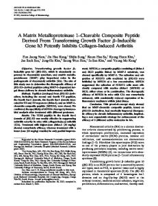
A contour plot of the curves of constant value on the Luminance CSF of the HVS is shown in the left panel of Fig. 3. Axis units are in cycles per degree of subtended angle. These units are convenient because they remove dependence on viewing distance and physical pixel size. The outer limit of vision is shown by the thick black curve. Beyond this, the average person cannot see detail so any displayed information in this region is, in a sense, wasted. The right panel of Fig. 3 shows only this limit curve for luminance plus the limit curves for each of the HVS opponent colour channels. It is seen that we have between one third and one half the visual bandwidth in these channels as in luminance. It is this difference in bandwidth that allows the algorithm of [5] to work. 2D Spatial CSF Level Contours
30
Maximum Visible Frequency (luminance)
25
Vert SF
Vert. Spatial Freq. (cy/deg)
35
20
15
10
Ymax
U := B−Y V := R−Y
Vmax
Umax
5 0 0
5
10
15
20
25
30
35
Horiz SF Fig. 3. Left: Contours of constant value for the Luminance CSF of the HVS. The black boundary represents the limit of human vision at about 31 cycles/degree (subtended angle) horizontally and vertically and somewhat less diagonally. The diagonal anisotropy is sometimes called the oblique effect. Right: Limits of the 2D CSF for Luminance and the two Opponent Colour Channels. The latter are between a third and half the bandwidth of luminance in the HVS. Horiz. Spatial Freq. (cy/deg)
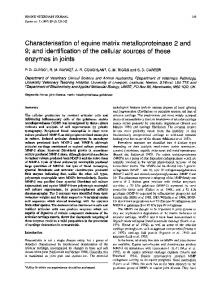
In the top portion of Fig. 4, (Fig. 4a), we show four representative sampling schemes. Our unit sampling structure is a pixel from an ordinary RGB striped matrix display, shown on the left. On the far right is a display having twice the horizontal and vertical resolution of the unit display. In neither of these is subpixel sampling assumed. We assume that the viewer is sitting at a distance from the displays such that the horizontal and vertical limits of vision are at the Nyquist for the 2× H & V pixel structure. This assumption is indicated by the R, G, and B spectral footprint in Fig. 4b directly below the 2× structure. Notice that the horizontal and vertical band edge is just at the limit of visual luminance. Diagonal components, supportable by the display, fall outside our ability to see them and so the display is wasting bandwidth. The notion of waste is not merely philosophical. Since a display’s manufacturing cost is roughly proportional to gate and transistor count, having more (sub)pixels than necessary incurs a real cost.
R
G
B
G B
G
Unit
Vert SF
R,G,B
R R,G B
Vert SF
CSF contours of HVS upper limit
Vert SF
Vert SF
B
2x H&V Ord. Rendering
R,G,B
(b)
Vert SF
Y,U,V
U,V Y
Horiz SF
Y
V U
Horiz SF
Vert SF
Horiz SF
R,G,B
Vert SF
Horiz SF
Vert SF
Here we give a justification for why 2D subpixel geometries are important. In fact, a few commercial groups have already begun considering the problem, primarily from a manufacturing viewpoint. Some examples of proposals may be found in [8]. The following is a “zeroth order” analysis of the spatial spectral properties of one such example compared with subpixel rendering on a striped display—all with the human visual system (HVS) in mind.
(a)
G
RGB Stripe
Pentile Subpixel rendering
Subpixel rendering
Ordinary Rendering
R
2. Motivation for 2D Subpixel Geometry
RGB Stripe
RGB Stripe
sation contains explicit constraints that allow it to be tailored to a given subpixel geometry.
Y,U,V
(c) Horiz SF
Horiz SF
Horiz SF
Horiz SF
Fig. 4. (a) Four sampling schemes and their associated (b) RGB and (c) Y U V spectral footprints. The spectral footprint for R, G, and B, on the left side of Fig. 4b, for the Unit pixel display, is easily understood. The spatial sampling frequency is half of the 2× display so the spectral foot print is half as large horizontally and vertically. When subpixel sampling is used on such an RGB striped panel, no advantage is gained in the individual colour planes. Each has the same sampling frequency as before so the spectral footprint for the primary colours is also unchanged, as shown by the plot in Fig. 4b under the second pixel from the left. Now consider one interesting example of a 2D subpixel structure, the PenTileTM II pattern [8]. The the R and G samples fall on a so-called “offset” sampling lattice so their associated spectral footprint has the well-known diamond shape shown in the plot below the PenTile structure. The B plane, on the other hand, is sampled on a square lattice with spatial period equal to the Unit pixel display and so has the same spectral footprint as the Unit. The interesting behaviour is shown in Fig. 4c where we consider the spectral shapes of the luminance, Y , and the two chrominance components, U and V . For simplicity we assume that R and G make equal contributions to Y , and that B makes none. We also assume that U = B − Y and V = R − Y , i.e., that our opponent colour space is nearly that of NTSC. For this “zeroth order” analysis, this turns out to be an acceptable approximation to the visual opponent colour channels. The spectral footprints of Y , U , and V for both the Unit display and the 2× display are clear. In these two cases, all colour components in the former are sampled at half the rate as the latter so its footprint is half as wide in H and V. For the RGB stripe display with subpixel sampling, we reap a 2× gain in luminance resolution in the horizontal direction because the R and G subpixels can now independently participate in adding information to the luminance field.3 Vertically there is no benefit to Y . For U and V , the footprints are limited by the periods of the B and R components they contain. Hence there is no gain in chrominance bandwidth over traditional sampling. In addition, if pre-filtering commensurate with the desired luminance bandwidth is done, then colour aliasing will occur. So the 1D RGB striped display has the double disadvantage that the vertical resolution of Y 3 In this case the horizontal luminance is non-uniformly sampled. Nonetheless the non-uniform sampling theorem guarantees the indicated available spectral width as long as the non-uniformity is taken into account during reconstruction.
SID 04 DIGEST • 1475
55.3 / D. S. Messing is significantly below the visual system’s ability to see, and colour aliasing will occur if one wants to preserve the horizontal resolution of Y . The 2D PenTile geometry suffers fewer disadvantages. There is still “too much” diagonal Y resolution for the HVS but since the cost of this pixel is just 5 subpixels instead of 12 for the 2× display, the real manufacturing cost is considerably lower. The V signal likewise surpasses the HVS, being limited by the sampling lattice of its R component. The extra available bandwidth, however, nicely prevents aliasing of this component if the input image is filtered commensurate with the HVS luminance limit. The U component is much smaller, being limited by the blue lattice, but it just surpasses the HVS ability in this channel so there is no waste. On the other hand one can expect some aliasing in this component if the image is filtered commensurate with the Y bandwidth of the HVS. In the next section, we discuss an approach to rendering and antialiasing on such a 2D lattice.
3. A Framework for 2D Subpixel Rendering Two-dimensional subpixel geometries present some problems not seen in the 1D striped case. The very definition of pixel comes into question because, depending on its centroid, different combinations of subpixels are needed to render a “white dot”. Also, for subpixel geometries like the PenTile pattern, the MTFs of different subpixels are different, making difficult a precise analysis based on space-invariant methods. For these reasons we view the rendering problem as an optimisation problem, similar in spirit to the development by Platt in [7] for 1D striped displays. In that account one starts with full-colour high resolution image samples, xn , sampled at the subpixel locations of the target display. Scalar-valued display subpixels are denoted by αn . The RGB striped display geometry dictates that the αn alternately represent a red, green, or blue subpixel as a function of n mod 3. The index, n, denotes4 horizontal subpixel position. The optimisation problem is formulated to minimise, with respect to a perceptually relevant metric, an error based on E n = Mn αn − Cxn where C is a 3 × 3 matrix that transforms xn into an opponent colour space and Mn = 3C n mod 3 . The solution is an array of 1D resampling pre-filters, illustrated by Fig 5, where an input scanline, x, is filtered and subsampled to yield an output display scanline α. The matrix nature of the prefilter is due to the error being defined in a colour space different from the input/output colour space. For the present discussion, the salient feature of the development in [7] is that the optimisation is unconstrained. That is, the optimal solution satisfies ∇E(α) = 0 where E is a weighted quadratic function of the transform of {E n } where the transform domain weights model the CSFs of the visual system’s luminance and chrominance channels. To be sure, there are constraints but they are implicit in the definition of α—the colour of a particular αn can only be one component colour of the input colour space, never a combination. 4 assuming
vertically oriented stripes.
1476 • SID 04 DIGEST
R
G
B R
G
B
Fig. 5. General vector-valued filtering of a vector-valued signal. Primary cross-colour dependencies occur because minimised error is defined in an opponent colour space instead of the input space. The framework we propose sets up a constrained optimisation problem of the form X ∇E(˜ x) + λi ∇Gi (˜ x) = 0 (1) i
∀i Gi (˜ x)
=
0
(2)
where the Gi are constraints, the λi are associated Lagrange multipliers, and where E is, again, a weighted quadratic function of the 2D transform of the {E mn }. Now, however, E mn = C(˜ xmn − xmn ) where xmn is the sampled scene, and x ˜mn is a full colour display sample at the subpixel indexed by (m, n). Before constraints are imposed, we assume that “subpixels” of the target display have full colour capability. To simplify the analysis we also assume that the scene is sampled on the same lattice as x ˜. The constraints, Gi , control the behaviour of each subpixel in the display. For example, to define a green subpixel at display lattice location (m, n), one imposes two linear constraints x) = x ˜0mn , Gi1 (˜
x) = x ˜2mn , Gi2 (˜
(3)
where is the c input colour component of x ˜mn . Eqs. 3 state that the 0 (red) and 2nd (blue) components of x ˜mn will be forced to zero when Eq. 2 is applied. th
x ˜cmn th
We now set up the constrained optimisation problem for the PenTile display pattern discussed in §2 and shown on the left side of Fig. 6. Henceforth we refer to this pattern as a macro-pixel. Pentile II
Modified Pentile II G
R
~ xm,n
~ xm,n+1
B G
R
~ xm+1,n ~ xm+1,n+1
Fig. 6. Fundamental PenTile II tessellating pattern (left). PenTile pattern modified for analysis (right). To facilitate the setup, we first modify the macro-pixel pattern to that shown on the right of Fig. 6. The grey patches represent yet-tobe-constrained “subpixel” positions. We have removed the central blue subpixel and will distribute its contribution equally among the four patches via constraints. Since the current framework does
55.3 / D. S. Messing not take into account the effect of subpixel MTF (shape) the solution will be independent of the shift in subpixel centroid position. 5 Seven simple linear constraints (per macro-pixel) on the x ˜ mn yield the desired subpixel pattern: x) = x ˜1m,n , Gi1 (˜ x) = x ˜0m,n+1 , Gi2 (˜ x) = x ˜0m+1,n , Gi3 (˜ x) = x ˜1m+1,n+1 . Gi4 (˜
5. Conclusion
x) = x ˜2m,n − x Gi5 (˜ ˜2m,n+1 , x) = Gi6 (˜
x ˜2m,n
x) = Gi7 (˜
x ˜2m,n
−
x ˜2m+1,n ,
−
x ˜2m+1,n+1 ,
(4)
The quadratic form of E implies that the gradient may be written as a linear (affine) system ∇E = A˜ x − r. We can therefore write Eqs. 1 and 2 as � h i�x ˜ = r, G(˜ x) = 0 (5) A G0 (˜ x)T Λ where G0 , the differential of G, has ∇Gi (˜ x)T as its ith row. This system is non-linear, in general, due to G and G0 . But our constraints are linear. Hence G(˜ x) reduces to G˜ x and G0 (˜ x) is independent of x ˜. Therefore Eq. 5 can now be rewritten as an augmented linear system � �� � h i T x ˜ r A G0 = . G 0 Λ 0 The operators A, G0 and G depend only upon the display and not upon the data. Furthermore, the simplicity of the on/off constraints makes G0 and G sparse, reducing the complexity of numerical solution.
4. Chrominance Post-processing The optimisation framework presented in §3 minimises a perceptual error relative to the `2 norm, i.e., in the least-squares sense. It is well-known that a reduction of least-squares error does not always result in a reduction of perceived error, even when that error is defined in a perceptually relevant way. In addition it is known that the chrominance errors made by the subpixel rendering process carry valid high-resolution luminance information. These two considerations suggest that we amend the proposed rendering framework of §3 to minimise only the luminance error, and ignore whatever chrominance errors the process makes.6 Then, after the Lagrange minimisation is performed, chrominance error is postprocessed as discussed in §1, Fig. 2, and reference [5]. In particular, chrominance aliasing error is high-pass filtered in accordance with the chrominance CSF of the visual system to remove those components that would be visible and leave those that would not, thus retaining a majority of high-resolution “luminance carrying” chrominance aliasing. Such a high-pass post-processing step requires a pre-processing step wherein the incoming RGB image is split into achromatic and a chromatic channels. The achromatic channel is processed as indicated above so that the only colour signals that come out of the 5 which
achromatic rendering process are the result of aliasing. A separate rendering process is used on the iso-luminant colour channel to preserve and retain as much of the original image colour as is possible.
for the unmodified PenTile II results in a (weakly) non-uniform subsampling of the red and green colour fields. 6 This is accomplished by appropriate adjustment of the transform domain perceptual weight functions discussed in §3.
In this paper we have motivated the need to consider 2D subpixel geometries and presented a general framework for solving the rendering problem on such displays. The PenTile II pattern provides an interesting real-world example of a 2D geometry to which we applied our framework. Although not discussed here, we have also applied the constrained optimisation framework to the 1D striped pattern treated in [7] and shown that Eqs. 1 and 2 contain Platt’s solution. There are several advantages to our framework. For one, if the unconstrained display is assumed to be densely sampled, constraints can be applied to model different subpixel shapes, as well as the black mask areas. In addition, the solution to the constrained problem provides not only filter coefficients but the Lagrange multipliers, λi . Each λi can be interpreted as measuring the rate of decrease of the error if the corresponding constraint is lifted. This means that for the on/off constraints, the magnitude of the associated λi measures how much one gains by adding an additional subpixel. This information, in turn, could be used to explore novel display geometries and assist in determining a possible optimal geometry subject to given manufacturing and image quality criteria.
6. References [1] Ron I. Feigenblatt, “Full-color imaging on amplitudequantized color mosaic displays,” in Digital Image Processing Applications, Los Angeles, Jan. 1989, Proc. SPIE, vol. 1075, pp. 199–205. [2] John Kranz and Louis Silverstein, “Color matrix display image quality: The effects of luminance and spatial sampling,” SID Int’l Symp. Digest of Technical Papers, pp. 29–32, 1990. [3] Claude Betrisey et al., “Displaced filtering for patterned displays,” SID Int’l Symp. Digest of Technical Papers, vol. 31, pp. 296–299, 2000. [4] Michiel A. Klompenhouwer and Gerard de Haan, “Subpixel image scaling for color-matrix displays,” Journal of the SID, vol. 11, no. 1, pp. 99–108, 2003. [5] Dean S. Messing and Scott Daly, “Improved display resolution of subsampled colour images using subpixel addressing,” in Proc. Int. Conf. Image Processing (ICIP’02), Rochester, N.Y., Sept. 2002, IEEE Signal Processing Society, vol. 1, pp. 625–628. [6] Scott Daly, “Analysis of subtriad addressing algorithms by visual system models,” in SID Int’l Symp. Digest of Technical Papers, San Jose, June 2001, vol. 32, pp. 1200–1203. [7] John C. Platt, “Optimal filtering for patterned displays,” IEEE Signal Processing Letters, vol. 7, no. 7, pp. 179–180, 2000. [8] Candice H. Brown Elliott and Michael F. Higgins, “New pixel layout for by pentile matrix architecture,” in 2nd Int’l. Display Manufacturing Conference, Seoul, Korea, Jan. 2002, SID.
SID 04 DIGEST • 1477