Malaysian Journal of Computer Science, Vol. 16 No. 2, December 2003, pp. 81-96
VON-DATA HYBRID SYSTEM ARCHITECTURE Adnan Shaout Yarmouk University Hijjawi College For Applied Engineering Computer & Control Engineering Department Irbid, Jordan E-Mail:
[email protected]
Atif A. Nsour Yarmouk University Hijjawi College for Applied Engineering Computer Engineering Department Irbid, Jordan E-Mail:
[email protected]
ABSTRACT In this paper a computing system has been proposed which involves both the principles and the approaches of data flow and Von-Neumann systems. The proposed model incorporates several new features like having a dedicated graphical processor, error correcting algorithms embedded in a systolic array and limiting the addressing mode to improve the execution speed. The proposed architecture can also function as a static and dynamic machine. Keywords:
Data Flow, Von-Neumann, Hybrid, Architecture, Computation
INTRODUCTION The computations, the processing of tasks and instructions have come along way since the early analog computers came into existence in the early fifties. The popular method of executing the individual instructions of a program in an ordered way is called the Von-Neumann method. When a program is rewritten efficiently or if a compiler can group all parallel tasks and execute them simultaneously, this method is unsuitable for large programs where many instructions can be executed in parallel. In late seventies researchers started applying data flow principles to programs which had inherent parallelism. This method offers interesting advantages over detection and execution of parallel tasks. But application of these data flow principles to execute parallel tasks has not yet become popular because of two reasons. First the data flow languages are totally different from the conventional languages and secondly, the data flow computers are still evolving. Moreover, the data flow computers offer little advantage when there is large number of sequential instructions in a program. One interesting concept is to take the advantages of both the Von-Neumann and the data flow models. The idea behind a hybrid architecture evolved from two facts: a) The software development for the data flow systems proved to be very slow. There was no agreement by the research community as to whether to settle for a language totally dedicated to the data flow system or to translate an existing higher level language and encode it into a functional language. Moreover, programmers familiar with existing languages like FORTRAN or PASCAL found it hard to adjust themselves to rules like single assignment of variables, and b) Data flow systems were found to be very slow when programs exhibited large amount of sequential instructions. The very first hybrid architecture proposed by Buerer et al [1] included a program counter to a static data flow machine so that sequential instructions can be executed in a Von-Neumann way. Special instructions like reset, iread, wread and swake were used so that data tokens from different instructions can be accessed from the memory in the least possible time. But this model did not deal with the hardware implications. The ‘Ianucci’ model proposed by Robert Ianucci [2] improved the previous model by separating the sequential instructions and routing them through a register called the frame base register which acted as a program counter. A pipeline stage was also added to improve the execution time. There are hybrid architectures which can convert programs written in a conventional languages into a data flow code and then execute streams of instructions in both Von-Neumann and data flow models. These architectures modify the Von-Neumann computer so that parallel tasks can be executed in the data flow way. However, this 81
Shaout and Nsour
paper develops a hybrid architecture which takes a graphical program as its input, checks it for any errors and executes the program in both the conventional as well as data flow methods depending on whether the instructions are dependent on each other or not. By graphical programs, we mean that all the instructions are coded with icons instead of texts that are normally used in higher-level languages. By errors, we mean violations of rules that are unique to data flow systems like not naming a variable in a program twice. We call the hybrid architecture in this paper as Von-Data architecture or in short as V-D architecture and in the following sections, the various hardware modules of the proposed architecture will be discussed. 1.0
MEMORY LATENCEY AND SYNCHRONISATION
Sophisticated compiler systems combined with extremely advanced pipelines have been used to take care of bounded memory latency problems. Unfortunately in the case of multiprocessing systems this problem is still not solved properly due to poor hardware support for inexpensive dynamic synchronisation [3]. Latency is defined as the time that elapses between making a request and receiving a response. This idle time can be used to do some other tasks that are waiting to be executed. This is caused by the physical partitioning of the system. The second issue of concern is synchronisation, that is, how to time all the related activities. This always results in a fixed time lapse to schedule different activities and other related events. This problem is basically due to the logical partitioning of the multiprocessing system. Synchronisation also becomes important when programs have to be decomposed so that parallelism can be exploited. When such program decomposition takes place, individual segments of the program should communicate with each other effectively and this can be done only through proper and efficient synchronisation. The issues of latency and synchronisation are closely interrelated. For example to avoid waiting for processors while their requests are being responded to, they can be switched to some other jobs that are waiting and this can be done only through proper synchronisation methods whereby correct context switching between various processors and the waiting events are done. The criticality of sequential instruction of the Von-Neumann type of computations is that it does not support concurrent processing. This is also supported by the fact that Von-Neumann machines provide very poor synchronisation at very low levels of computations. To understand this, let us see how synchronisation is being done in conventional machines for low grains. To participate in any synchronisation event, a common ground is required for the synchronisation to happen. This may take the form of a semaphore, a register, a buffer tag, an interrupt level or any similar devices [4]. In all these cases, one can think of the common ground as the name of the resource being used. It should be clear that the number of simultaneously pending synchronisation events is bounded by the resource space as well as by the cost of these synchronisation events. This severely reduces the chances of dynamic synchronisation. Most of the Von-Neumann machines have synchronisation mechanisms, which are of large grain, a classic example of being the interrupt systems. The cost of these operations is quite high and is not really suitable for controlling the latency problem. Moreover, since suspension and resumption of events involve expensive context switching, exploitation of parallelism by decomposing a program into smaller segments does not really result in speed-ups. These points indicate the need for altering the structure of the Von-Neumann methods. But it is a known fact that as long as the data dependencies can be worked out at compile time, the sequential style of Von-Neumann method provides better control over a machine states than by any other systems. When sequencing instructions in a program cannot be optimised at the compile time, then dynamic scheduling and low level synchronisation can be used to optimise the execution of a program. 2.0
HYBRID ARCHITECTURE
A simple idea is that Von-Neumann and Data flow systems are not diametrically opposite to each other but they are just the opposite ends of a same spectrum. There can be a system, which combines the good points of both systems, and the hybrid architecture can deliver optimum results in the concurrent execution of parallel tasks.
82
Von-Data Hybrid System Architecture
Starting with the observation that the cost associated with data flow instruction sequencing in many cases are prohibitively expensive, we can implement the data flow concepts only during the inter procedural level there by retaining the advantages of the data flow systems. But this will result in giving up the most important benefit of the data flow systems, namely the ability to context switch very effectively at very low grains, thereby avoiding memory latency that is so common in Von-Neumann machines. To solve this problem, we have to find out what hardware supports are necessary to avoid memory latency and the cost involved in synchronisation operations. For machines capable of executing many parallel tasks at very low levels of computations, executing programs which are sequential in nature will involve more memory latency than in systems where programs can be decomposed into smaller segments. Therefore the hybrid architecture should have the capability to decompose its programs into smaller parts so that individual parts can be executed independently and concurrently without any sequencing constraints. There should be a facility wherein processor synchronisation need not be done very often even if sequential execution of instructions is to be done. 3.0
SYNTHESIS
The basic idea of the new hybrid architecture revolves around both the Von-Neumann and the data flow architectures. The unit of parallel computation in a Von-Neumann system is the task. The synchronisation between various tasks is expensive if they are to be done through software. This cost can be justified for large tasks especially if they are not done very often. Also within a task, synchronisation is done implicitly through the ordering of the instructions. Explicit synchronisation is done between various barriers through semaphores, interrupts etc. Context switching is done usually at the synchronisation points and the number of such switching between various instructions becomes a performance factor. But in a data flow system, the inter-task synchronisation is performed by the hardware and no instruction is activated until all the operands are available to the nodes and due to this, a very high degree of parallelism is achieved. 4.0
PARTITIONING OF GRAPHS
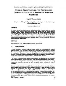
If we consider Fig. 1 where a simple data flow graph is given. There is some potential parallelism in this graph [2]. For example, instructions 11 and 15 do not depend on each other. They depend only on the availability of operands a, b and c. Consider the example of instructions 12 and 13, after instruction 12 has been executed, instruction 13 can be executed immediately since it does not depend on anything else. Instructions 12 and 13 in fact have the same input and output characteristics and have similar synchronisation requirements. It is to be noted that this pair of instructions can only be done sequentially. Now we can allow the compiler to collect all the groups of instructions that are dependent on each other and these sets of instructions can then be executed using a Von-Neumann model. There is no loss of functionality here, since the instructions that are dependent on each other have to be executed sequentially in a Von-Neumann style even in the data flow approach. This is the basis of the new proposed hybrid V-D architecture. The system takes advantage of the inherent fine grain parallelism provided by the data flow approach and also has a program counter to sequentially execute those instructions that are dependent on each other. The advantage in this type of processing is that context switching has to be done only between instructions that can be executed in parallel with those dependent ones. Hence a good degree of proper synchronisation is made possible. Moreover, memory latency is greatly reduced because the processors are switched only between sequential and parallel instructions. The basic architecture will largely retain the data flow system but only the processor will have certain modifications. Before we go into the hardware considerations, we have to find ways of partitioning the data flow graphs so as to separate the dependent instructions from those of parallel instructions.
83
Shaout and Nsour b c
a
11
15 SQ2
16
12
SQ1 13
14
Fig. 1: Partitioning of sequential nodes in a data graph Poor partitioning can take away the inter-procedural parallelism that is present in the original program. In fact, the desire to segregate dependent instructions does not mean restricting the parallelism that is inherently present. Of course, it has to be noted that the larger the number of dependent instructions, the lesser the degree of concurrence in the actual program. We also have to note that arcs from independent instructions can cross into the arcs of the dependent instructions. These cross over points have to be dynamically synchronised during the run time. We have to be careful also about deadlock avoidance. This arises in non-sequential instructions that cannot be made independent of the program inputs. Therefore, it is necessary to determine where this dynamic ordering will arise in the data flow graphs or the codes that are generated from it. The major advantage of sequential instructions is that they can be pipelined so that execution can proceed faster while at the same time independent instructions can be executed in a data flow atmosphere. The overall result is that the run time of the whole computation is vastly reduced. Fortunately in this case this kind of node partitioning has already been done for many applications such as critical path method which does it in two ways: breadth first and depth first. The interested readers will find the topic of partitioning covered in detail in the given references [5, 6]. 5.0
HYBRID ARCHITECTURE MODULES
In this section, description for the various modules of the proposed architecture will be discussed. Fig. 2 shows the proposed V-D architecture. 5.1
Data Driven Array Processor
The algorithm for finding the dependency in the execution levels are embedded in the data driven array processor so that the execution speed up achieved is higher when the sequential instructions are routed for execution to a VonNeumann type processor. The input algorithm is first converted into a data flow graph then it is mapped into a data driven array. We present here a generalised way to map an input algorithm into an array so that even if the algorithm is improved, the method will remain the same. The array is a wave-front array which is totally asynchronous. The wave-front is chosen over a systolic array because correct sequencing of the algorithm is more important than the correct timing. Logically the computation sequence of these arrays advance in the same way as the systolic arrays but the speed of the propagation is not the same. Since the speed of different computations is not the same, it becomes easy to time and synchronise individual tasks in the processor array. This is because some operations are inherently faster than others (multiplication versus addition) or due to the dependencies of the data. We also choose to map the algorithm into a processor array because it is not computationally demanding.
84
Von-Data Hybrid System Architecture
Data driven array processor
Router
Packet switched network
PE's
I-Structure memory
Fig. 2: Architecture of a hybrid machine The processors in the array will execute the operations in the corresponding data flow graph while the interconnections of the array will be the arcs of the data flow graph. Fig. 3 shows the data flow graph representing the computation of the two coefficients A and B in the solution of y (t) = A cos(wt) + B sin(wt) of the spring mass system with an external force F(t) = F0 cos(wt). W
W *
M
w2
* Mw2
k
W
C
- k-Mw2
wc
*
(k-Mw2)2
w2c2
*
*
FO
+ w2c2+(k-Mw2)2
/ FO/w2c2+(k-Mw2)2
*
*
A
B
Fig. 3: Flow graph for the spring constant equation These coefficients are computed from A = F0{k - Mw2 / (k - Mw2) 2 + w2c2} B = F0{wc / (k - Mw2) 2 + w2c2} where k, M and c are given constants Fig. 4 gives out a possible mapping of the graph in Fig. 3 onto a regular array processor.
85
Shaout and Nsour
The hexagonal topology of the array serves only as an example of a regular array. The data flow representation enables the exploitation of concurrency at the lowest possible level by treating each instruction as an independent activity [7].
*
*
k
w
w
M
w
-
A
*
*
*
c
*
*
/
+
B F0
Fig. 4: Mapping of the spring equation in hexagonal array In this way fine grain parallelism can be achieved. For example, the products w1 and w2 in Fig. 3 can be executed at the same time. When an arbitrary algorithm executes in an array, in general no regular propagation of computational front takes place. Hence to speed up the execution of arbitrary algorithms, we need a more flexible array. Such array will allow the generation of new computational fronts and their cancellation at a later time depending on the arrival of data operands. That is why these arrays are called data driven arrays. In the data driven arrays, not all cells perform the same kind of operations. As a result, the operation time of different cells may differ substantially and subsequently the cells may receive their operands in an arbitrary manner. Therefore the cells should have the capacity to test for the presence of its operands and execute only the instructions for which all the operands have arrived. Thus the order in which the instructions are executed is data dependent. The wave-front arrays are also data dependent but only cyclic graphs can be mapped into them. The important feature of this approach is that data flow languages such as VAL and ID can be mapped into these arrays. The mapping of the arrays is changeable and hence its applications are countless. High fault tolerance is supported because faulty processors and communication networks can be reconfigured [8]. This technique is somewhat similar to the one used in configurable highly programmable array [9]. The functional blocks composing the cells are shown in Fig. 5. The communication control block contains the control logic and bus-interface for communicating with the rest of the cells. They are also connected to the packet switching network so that communication is possible with the rest of the system. Six registers are located in the periphery of the system. The number of such registers may vary, depending on the application. These registers are connected to a common interface bus through which data can be transmitted from one register to another and to the execution unit. These registers can be loaded or unloaded through the internal bus. In addition, these registers can also communicate with the registers of the adjacent cells. The transfer of data from registers to other units is through program control and the transfer of data within registers is through hardware control. The instruction memory contains instructions specifying the operations that the cell has to perform on the operands it receives. It has an address counter and registers that hold the pages of the data registers (the address counter itself is a simple shift register which increments or decrements the count depending on the type of operation). It has two modes of operation, namely instruction loading mode and the execution mode. The flags control the data operation of the cells and the exact status of all registers are kept in this flag register. Through this, the cell can check whether a data register is empty and reloads. It also checks whether all the
86
Von-Data Hybrid System Architecture
operands for a particular operation have been received so that execution can be initiated. The flag array contains only the dynamic flags that change during the execution of the instructions. The static flags are kept in the instruction memory which indicates which registers are the operands for a given operation [10]. Communication Bus R6
R1 Internal Bus MPC EC FL
R5
R2 AC
IR IM
CC
Internal Bus R4
R3 Communication Bus
MPC = Micro-program control FL = Flags CC = Communication Control Block
EC = Execution Unit IM = Instruction Memory AC = Address Counter IR = Instruction Register
Fig. 5: Functional blocks of a hexagonal cell 5.2
Mapping Graphs into Arrays
Here, briefly present the mapping process whereby graphs are mapped into hexagonal connected PE array [11]. This contains four phases: 1. DF-program translation. 2. DFG-mapping into array. 3. Array partitioning. 4. Task to PE assignment. The first stage is the translation of a data flow program into a data flow graph. This stage is general and does not depend on any specific architecture. There are translators that are available for this purpose. Two examples of these translators are the Lexical Analyse Generator and Yet Another Compiler; both based on UNIX and are widely used at MIT. Translation proceeds by analysing each construct in a program and translating it into a sub-graph. These sub-graphs when combined form the DFG program with high locality. That is, each control structure in the program will be a connected sub-graph in the DFG that simplifies the later stages. The second stage in the process deals with the mapping of the DFG onto processor array. Here the non-planar array is mapped into a hexagonal array. This does not depend on the topology of the array but only on technology. Array partitioning is basically the process through which an optimum number of PE’s are used so as to reduce the hardware. Allocation of tasks follows the same pattern as in the data flow graph principles.
87
Shaout and Nsour
5.3
The Router
The principal job of the router is to direct all the tasks with dependencies to a pipelined Von-Neumann processor and the independent tasks to a data flow processor to be executed in a concurrent manner. The data driven array gives out the Completion and Dependency levels, in short the C and D levels of all nodes in a data flow graph. If the D level of any node is zero, then it means that it can be executed immediately and if it is more than zero, then the nodes can be sequentially ordered into a processor that has a pipeline. 5.4
Packet Network
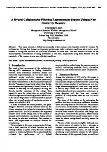
The packet switching network is similar to the one proposed by Chen and Hwang [12]. This is a multi-stage interconnection network (MIN) constructed by buffered 2-by-2 switches. Fig. 6 shows packet network as used in a typical multi-processing atmosphere. In MIN’s, a unique path exists between any source and any destination. When the packet traffic becomes heavy, then waiting queue length in some switching cells of a unique-path MIN may become too long to be acceptable. That is why a multiple path MIN has been used. The network itself is structured with buffered 2 by 2-switching cells. Multiple paths are created between any pair of source and destination by adding extra stages to the MIN’s. At each switching cell, there are two kinds of delay in passing a packet to the next stage: 1) The wait delay which is caused by a packet waiting in a cell buffer before it can be transmitted, and 2) The transmit delay which is the actual time needed for transmitting a packet to the next stage. The transmit delay of a fixed length packet is a constant between stages. The wait delay is a random variable. The sums of transmit delay and the wait delay at a switching cell is called a cell delay. The sum of all cell delays in the successive stages from the source to the destination is called the network delay. In a multi path network, packets can be transmitted to multiple paths. Therefore, the average wait delay in each switching cell is much shorter than in a unique path-switching network. However packets are transmitted with more transmitting delays in a multipathswitching network. When the packet load is light, the transmit delay dominates the wait delay.
Networks
Networks
Processors
Memory Modules
Fig. 6: An example of processor to memory network When the packet load is heavy, the wait delay entirely decides the network delay. The network performance is thus improved with less network delays. Fig. 7 shows a typical path switch network. The following types of networks are all served by the switching networks: a) Interconnection Networks b) Distribution Networks c) Arbitration Networks d) Control Networks. A decision must be made for each packet arriving at each input port to be switched into one of the two output buffer buses, waiting for the transmission to the next stage. The MINs play a vital role in the transmission of tokens to different parts of the system and from the fact that they are connected to all parts; they are similar to any other interconnection networks. An 8 by 8-interconnection network that we used is shown in Fig. 8.
88
Von-Data Hybrid System Architecture
+ Input port 0
Output port 0 Buffered Banks and packets. + Output port 1
Input port 1
Fig. 7: A multi-path switch networks Destinations
Sources 0
0
1
1
2
2
3
3
4
4
5
5
6
6
7
7 Stage 1
Stage 2
Stage 3
Stage 4
Fig. 8: An 8 by 8-interconnection network 5.5
The Processing Element
A single processing element is shown in Fig. 9. The processor, apart from having the standard features of a conventional data flow processor, also has a token address register, which receives the control signal from the control processor. When nodes having data dependencies are detected, then they are routed to any available processor. processor’s token address counter gets activated and the execution proceeds in a regular Von-Neumann style.
The
The data independent tasks face no such barrier and they get executed in a parallel manner according to the data flow models. The processor itself has a token queue unit, a match unit for matching the tokens having the same tags depending on whether a static or dynamic mode operation is performed. Following is an explanation of how the processing elements taking each module individually. 5.5.1 The Graphical Processor The graphical processor assembles the source data flow graph from the program memory and forms token streams such as numbers, names of the variables, various arithmetic operators such as adder, subtracter, multiplicater, reserved words for the operating systems etc. Then it forwards these arithmetic operations to the token queue or the matching queue as the situation demands. Execution speed minimisation takes place as the graphical processor operates in parallel with two other processors, the data and the control processors.
89
Shaout and Nsour
5.5.2 Data and the Control Processors The data processor contains the arithmetic and the logical unit and performs all the data operations such as add, subtract, multiply etc. It also executes all data declarations and builds a corresponding symbol table in its associative memory. Its internal registers handle all the subroutine calls and the storage management to and from the data memory. Whether tokens are executed sequentially or in parallel depending on the availability of the data, the control processor processes them to be executed. The control processor handles all the control structures of the graphical programs. Sub-routine calls, If-Then-Else, While - Do, Goto, Case, and Return and other procedures alter the flow of control of the source program. The control processor takes note of these procedural changes and changes the flow of control by altering the token address register. This resetting of the token address register makes the graphical processor fetch the correct sequence of tokens from the program memory. Graphical Processor
Program Memory
Token Queue
Matching Unit
Dynamic Scheduler
Token Register TYPE
Token Address Register
VALUE
Token Cash
Token Cash Type
Type
Value Data Memory
Pipeline
Location
Stack
Data-Processor
Control Processor
Data-Base-Register
Associative Memory
Associative Memory
Destination Computer
Fig. 9: The architecture of a hybrid processor The token address register is somewhat similar to the program counter of the conventional machines. If there are sequential nodes that depend on the previous firing of the nodes, then these set of nodes are scheduled by the control processor through the dynamic scheduler to be executed in a sequential manner. The token address counter acts like a program counter this time and increments the address of the instructions as dictated by the program flow. The control processor also has a cache and associative memory and a stack which keeps track of all the nesting statements.
90
Von-Data Hybrid System Architecture
5.5.3 Associative Memories The associative memory of the control processor contains several entries, each containing one control statement. If a graphical program has three If statements, two Do loops and two sub-routine Calls, the associative memory of the control processor will have seven entries. Whenever the control processor comes across a control statement, it searches through the associative memory to get the required control statement. Likewise the associative memory of the data processor contains the types of the data variables, whether a variable is real or imaginary or a floating point etc. It also contains the location of these variables as in the program memory. It is to be noted that associative memories are created only during the run-time and the execution time of the original graphical program. Table 1 briefly describes functions of the various registers. Table 1 Functions of different registers within a processing element Type
Processor
Function
Program Token Register (Type) Token Register (value) Token Address Register Data Base register
Graphical Data
Stores the original source program. Stores the type of the token variable.
Data
Stores the value of the token.
Control Data
Contains the location of the tokens. Acts as a buffer for data associative memory. Contains the location of the control structures.
Stack
Control
To illustrate the operation of these processors, let us take the following iterative operation: The integer power z = xn desired. input x, n y = 1; I = n while I > 0 do begin y = y* x; I = I - 1 end z=y output z The data flow graph corresponding to the above equation is shown in Fig. 10, and the snap-shots of the first execution cycle are shown in Fig. 11 and Fig. 12. The program memory contains the locations of all the inputs as well as the control structure and whatever they are in the original source program. The above iteration is static if the value of ‘n’ is known already. In case the value of ‘n’ is not known at the start of the program, then the successive values of ‘n’ can be written into the program memory by the control processor and the machine can be run as a dynamic one at the same time. The architecture presented is unique in two ways: First it combines both Von-Neumann and data flow operations. The token address memory acts as a program counter when sequential operations are encountered. During this time, it increments the address of the instructions, fetches the new addresses if there are any branching or conditional expressions and routes all of these to a pipeline. The nodes that are not dependent on each other can be executed directly using the data flow operations. The only type of language allowed in this machine is the graphical one.
91
Shaout and Nsour
1
x F
T
T
n
F
T
F
i y T
>0
F
T
T -1
X
Z
Fig. 10: The data flow graph for z = xn LI 1 2 3 4 5 6 7 8 9 CI
x n 1 i 0 > y = ; * - z
i n p u t
w h i l e
LI = Location of Instruction
d o
b e g i n
e n d
CI = Content of Instruction*
* Content can be both data and control variables
Fig. 11: An example of data and control variables stored in the program memory
Token Register TYPE
VALUE
INT
Token Address Register
x
1
x
Destination Computer
00
Data Memory
x n 1
Type Control Stack
While
1 2 3
Location 20
Fig. 12: An example of the states of the registers The architecture allows the viewing of the individual execution of the tokens. Since the anomalous detection algorithms are embedded in the hardware, the user can check the syntax and other errors directly in the process of writing the graphical programs. Secondly, the architecture itself can support both the dynamic and the static versions of data flow operations. This is made possible because of the matching unit. These new approaches are contrasted along with the two previous hybrid architecture models in Table 2 [13].
92
Von-Data Hybrid System Architecture
Table 2: Contrasting the features of previous hybrid models with the present architecture Author
Features
Ekanathan et al. 1989
Has a separate mechanism to empty global memory and lessen latency time. The matching unit has a trigger to speed up iterative operations. Uses functional programming and is a static machine.
Buherer et al 1988
Uses the sequential instructions for Von-Neumann processing. Blocks of sequential instructions are grouped together in a unit called ‘quanta’ for executions. Has a pipelining mechanism for speeding up the operations. Uses a frame base register for synchronising Von-Neumann and data flow operations. Separate instructions are used for conditional expressions. Uses functional languages and is a static machine.
Present model
A direct execution machine involving only direct addressing. Inputs only graphical programs. Can be both static and dynamic data flow machine. A token address register is used to synchronise explicitly the different tasks. Reduction of graphical programs and error correction methods are embedded in a wave front array. Future improvements of algorithms are possible in the architecture. Extra hardware costs for incorporating wave front array and the matching unit are involved. Provision for interactive programming and tracing of the individual token execution are made.
5.5.4 Token Queue This unit basically collects all the tokens that arrive from the external environment. In case of a large computation there will be thousands of token queues store some of the tokens that are not required immediately. The tokens that are enabled are sent to the matching unit. The unit has a read and write controllers to synchronise all the storing and transferal operations. The token queue is shown in Fig. 13. I/O
R/W
R/W/S To Matching Unit
T/S R/W = Read Write Controller R/W/S = Read Write Store Controller T/S = Token Store
Fig. 13: Token Queue Unit 5.5.5 The Matching Unit The matching unit is shown in Fig. 14 with its inner blocks. The token matching unit is the most critical part of the system. The matching store units are relatively large and can be accessed associatively with the labels and the destination fields of the tokens. The memory is a content addressable memory which is the basic requirement of any data flow system. It is noticeable; a separate pipeline stage precedes the main matching unit.
93
Shaout and Nsour
At this point, examining the bit of destination field determines whether matching is appropriate for this token package. The tokens for which matching are not appropriate are passed directly to the output buffer. A hash table search inside the matching unit then locates the partner for the remaining tokens. In this case, the hash key is used as an address to read the hash table which is parallely arranged. The label and the destination fields of all the accessed locations in the hash table are then compared with the corresponding sections of the input token package. Successful matching of the tokens then causes the matching entry to be deleted from the hash table and the matched token pair, together with its label the destination is then passed on to the output buffer. Unsuccessful matches normally cause the incoming token package to be placed at a free position within one of the parallel memory banks of the hash table which is still addressed by the hash keys. Occasionally, this will not be possible since all words addressed by the hash key already contain the non matching tokens. In this case, the systems depart from the conventional techniques. Instead of generating a new hash key and starting all over again, the controller routes the unmatched package to the overflow unit where it is processed once again. The advantage of the data driven notation is that subsequent token package can be handled out of their turn, provided their hash key is still intact. Over Flow Unit
Match Store Controller Distributor
A A = Arbitrator
Hash key generator
To Storage Unit Hash-Table
Fig. 14: Matching Unit 5.5.6 The Resource Manager and Dynamic Scheduler All allocations and routing of arrays, heaps, frames etc. are done by the resource manager. This is done dynamically during the program run time. The resource also keeps track of the starting and ending of the program and those nodes, which are not data dependent on other nodes, and can be fired independently. A resource manager may get multiple calls, which are handled by the dynamic scheduler. The dynamic scheduler keeps track of all the nodes in a flow graph and has a counter, which get decreased each time when the task is done. If a node execution involves access to other resource, the dynamic scheduler indicates this to the source manager. The scheduler also handles and routes multiple accesses of data in the first come first serve basis to the resource manager. Finally, it is the scheduler that routes the sequential instructions to the program counter to be executed in a conventional Von-Neumann way. A block diagram of the dynamic scheduler is shown in Fig. 15 and we briefly outline the functions of each block. The activity list contains the list of all nodes/tasks in the original program graph. D-level acceptor gets all the data dependency requirements from the data driven array processor. The router directs the sets of sequential instructions through a conventional program counter. If the tasks can be done independently, then they go directly into the pipeline unit by passing the program counter. For multiple tasks, the router communicates with other processors through the packet switching network and activates them. This is done for a system, which has more than one processor [14]. The pipeline unit is organised into the usual sections of instruction fetch, operand fetch and execution and storing mode. The advantage is that both the sequential (data dependent) as well as the data flow operations can be performed [15]. Each of the four sections can contain any number of stages. This is to account for the timings for the memory and operation units. There are two distinct advantages in using pipelining in our hybrid-processor: certain pipeline problems can be handled very efficiently, and the dynamic scheduling unit can reduce the pipelined
94
Von-Data Hybrid System Architecture
gaps arising from data dependencies. This is because various sequences of instructions that are dependent on each other are already known. D- Level Acceptor Router
Activity List Enable Counter
N E T W O R K
Fig. 15: Dynamic scheduler Usually the operand fetch for an instruction must not occur until the operands values are stored. Also if the operand is the result of the previous instruction, the execution of the current instruction must be delayed until the previous instruction is completed. Consider Fig. 16, in normal pipelining; T1 and T3 can be pipelined only in one way. When T1 is getting executed, at the maximum, the instruction pre-fetch of T3 can begin in the pipeline. But the dynamic scheduler instead of following T1 with T3, follows T1 with T2. After T1 and T2 get executed, then only T3 and T4 are loaded in to the pipeline. Thus the sequential and the parallel instructions get executed in an interleaved way.
T2
T1
T3
T4
Fig. 16: Pipelining independent nodes The token address register keeps track of the sequential instructions that are executed and passes the information to the activity list in the dynamic scheduler. The pipeline units are fully utilised even when scalar parallelism is available. This is because the dynamic scheduler keeps track of all the data dependency relations of nodes and fills up the various stages of the pipeline unit. CONCLUSION New hybrid architecture is presented here which makes use of the Von-Neumann as well as the data flow approaches. The model supports both the static as well as the dynamic data flow models with the addition of a matching unit. Only direct addressing is permitted so that execution can take as little time as possible. The writing of the graphical programs is totally inter-active and any programming errors can be corrected at the time of writing the program itself. The different states of the tokens can be watched as the execution proceeds. Future improvements and modifications of different algorithms are readily possible because these are embedded in the wave-front array. Also simulation for the new architecture is underway.
95
Shaout and Nsour
REFERENCES [1]
R. Buerer and K. Ekhanathan, “Incorporating Data Flow Ideas into Von-Neumann Models”. Transactions on Computers, Vol. C-36, No. 12, Dec. 1987, pp. 1515-1521.
IEEE
[2]
R. Iannuci, “Towards a Von-Neumaan/Data Flow Type Architecture”. IEEE Transactions on Computers, Vol. 24, No. 4, April 1988, pp. 131-139.
[3]
Arvind and R. Iannuci, “Two Fundamental Issues in Multiprocessing”, Proceedings of the DFLVR Conference on Parallel Processing, Bonn, Bad-godesburg, June 1987.
[4]
G. W. Cox and W. M. Corwin, “Interprocess Communications and Dispatching on the INTEL-432”. ACM Transactions on Computer Systems, Vol. 1, No. 12, Feb. 1983, pp. 45-46.
[5]
L. Bic, “A Process Oriented Model for Efficient Execution of Data Flow Programs”, Proceedings of the Seventh International Conference on Distributed Processing, Berlin. West Germany, Sept. 1987.
[6]
K. Ekhanathan, “Multi-Tasking on Data Flow Type Architecture”. Technical Report. RC-12307. IBM. Thomas J. Watson Research Center, NY, Nov. 1986.
[7]
J. B. Dennis, “A Data Flow Super Computer”. IEEE Computer, Vol. 13, No. 11, Nov. 1988, pp. 362-376.
[8]
I. Koren and G. M. Silverman, “A Direct Mapping of Algorithms on to VLSI Based on Data Flow Approach”, Proceedings of the International Conference on Parallel Processing, Aug. 1983, pp. 335-337.
[9]
J. A. Abraham, “Fault Tolerance Techniques for Systolic Arrays”. IEEE Computer, Vol. 20, No. 7, July 1987, pp. 65-67.
[10]
I. Koren and B. Mendelson, “A Data Driven VLSI Array”. IEEE Computer, Vol. 21, No. 8, Oct. 1988, pp. 30-37.
[11]
M. Mendelson and G. M. Silbermann, “Mapping of Data Flow Graphs on VLSI Array Processors”, Proceedings of the International Conference on Computer Architecture, June, 1987.
[12]
Chi-yua Chen and K. Hwang, “Packet Switching Networks for Multiprocessors and Data Flow Computers. IEEE Transactions on Computers, Vol. C-33 No. 11, Oct. 1988, pp. 990-997.
[13]
J. M. Moreno and T. Lang, “Matrix Computations on a Systolic type Meshes”. IEEE Computer, Vol. 23, No. 4, April 1990, pp. 32-38.
[14]
Arvind and R. S. Nikhail, “Executing a Program on MIT Tagged Token Data Flow Computer”. IEEE Transactions on Computer, Vol. C_39, No. 3, March 1990, pp. 183-189.
[15]
J. B. Dennis and G. R. Gao “An Efficient Pipelined Data Flow Architecture”. IEEE Transactions on Computers, Vol. C-33, No. 4, March 1988, pp. 123-129.
BIOGRAPHY Adnan Shaout obtained his Ph.D. in electrical engineering from Syracuce University at New York. He is now Professor of Computer Engineering at Michigan State University, Dearborn. His research interests are: AI, Fuzzy Control, and Modeling and Simulation. Atif A. Nsour obtained his Ph.D. degree in computer engineering from Sind University. He then joined the Computer Engineering Department at Yarmouk University. His research interests are in the areas of computer architecture, traffic control and neural-fuzzy system applications.
96