1D-4
A 100Mbps, 0.19mW Asynchronous Threshold Detector with DC Power-Free Pulse Discrimination for Impulse UWB Receiver Lechang Liu, Yoshio Miyamoto, Zhiwei Zhou, Kosuke Sakaida, Jisun Ryu, Koichi Ishida, Makoto Takamiya and Takayasu Sakurai University of Tokyo, 4-6-1 Komaba, Meguro-ku, Tokyo 153-8505, Japan Tel: +81-3-5452-6253 Fax: +81-3-5452-6632 E-mail:
[email protected]
Pulse discriminator
Abstract - An asynchronous threshold detector for DC-960MHz band impulse ultra-wideband (UWB) receiver is proposed in this paper. It features a DC power-free pulse discriminator. The proposed architecture in 90nm CMOS achieves the lowest power consumption of 0.19mW and energy consumption of 1.9pJ/bit at 100Mbps in the UWB receiver.
High level thresholding PFD
In
I. Introduction
RXout InvH VL
IL
UP
InvL VH
IH
DN V1
Receivers for impulse UWB can be broadly categorized as threshold or leading edge detectors, correlation detectors, and RAKE receivers. Multi-user detectors (MUD) and hybrid RAKE/MUD-UWB receivers for robust narrowband interference suppression are becoming popular. However, a single clocked-correlator receiver [1] or threshold detector [2] can also be used for short distance and high SNR environments. In this paper a novel asynchronous threshold detector [3] is proposed for the ad-hoc wireless sensor networks. These ubiquitous networks require that the individual nodes are tiny, easily integratable into the environment, and have negligible cost. The proposed detector features a DC power-free pulse discriminator and an error-recovery phasefrequency detector (PFD), thereby achieving extremely low power consumption at 100Mb/s data-rate.
Low level thresholding
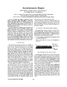
Fig.1. Proposed UWB receiver with DC power-free pulse discrimination.
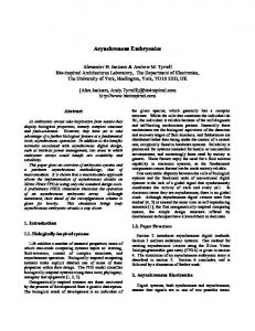
III. DC Power-Free Pulse Discriminator Conventionally, an amplifier and a comparator can be used as the threshold detector. The major disadvantage of this topology is large DC power dissipation that occurs even for no AC input. In the transmitted BPSK signal, the circuit spends long periods of time with no AC signal. Power dissipated in these periods is wasted. The operation principle of the proposed DC power-free pulse discriminator is shown in Fig. 2. Two unbalanced inverter InvH and InvL are employed to detect the positive pulse and negative pulse respectively. To tune the threshold of the pulse discriminator, variable bias voltages VL for the source input of the top inverter and VH for the bottom inverter are used. As shown in Fig. 3, the proposed pulse discriminator has essentially zero power dissipation for no AC input.
II. Asynchronous Threshold Detector An ultra low-power solution for BPSK demodulation is leading edge detection (LED) technique [3]. The LED receiver sets a threshold at the receiver, and any incoming pulse that crosses the threshold is detected and demodulated. The proposed asynchronous threshold detector is shown in Fig. 1. It consists of four building blocks: a front-end amplifier, a DC power-free pulse discriminator, an error-recovery phase-frequency detector (PFD) and a Reset-Set Flip-Flop (RSFF). The received signal is first amplified by the front-end amplifier and each BPSK symbol is split into two pulses by the proposed DC power-free pulse discriminator. Then the first incoming edge of the two pulses is detected by the PFD and the RSFF converts the detection result to the corresponding data bit.
978-1-4244-2749-9/09/$25.00 ©2009 IEEE
V0
Front-end amplifier
VDD=1V High level thresholding
ΔV VH
InvH
Logical VTH of InvH
In
VDD/2 InvL Low level thresholding ΔV
Logical VTH of InvL VL 0V
Fig. 2. DC power-free pulse discriminator.
97
InvL
0.7
“1”
“0”
250
0.3 100
ΔV=
200 Rx Power(μW)
InvH
IH+IL IL(μA) IH(μA) In(V)
1D-4
0 100 0 100 0 0
5
10 Time(ns)
15
0.25V 0.30V 0.35V
150 100
20
50 0 0
20
40
60
80
100 120
Data Rate (Mbps)
Fig.3. Simulated waveforms of pulse discriminator.
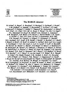
Fig. 5. Measured receiver power vs. data rate.
VI. Experimental Results A test chip without the front-end amplifier was designed and fabricated in 90nm CMOS process and the micrograph is shown in Fig. 4. The measured receiver power dependence on data rate at different bias voltage is shown in Fig. 5. The tradeoff between power consumption and sensitivity can be tuned by the bias voltage ΔV in Fig.2. Fig. 6 shows the comparison with the state-of-art UWB receivers. The proposed architecture achieves the lowest power consumption of 0.19mW and energy consumption of 1.9pJ/bit at 100Mbps in the UWB receiver.
[6] [7] [5]
100
10
[4]
1
This Work (w/o Amp) 1.9pJ/bit
[2] 0.1 10k 100k
10 0p J /b it 10 pJ /b it 1p J/b it
[9] [10]
10 nJ /b it 1n J/ bi t
Power (mW)
[8]
1M
10M
100M
1G
10G
Data rate (bps)
V. Conclusions
Fig. 6. Comparison with the published UWB receivers.
The proposed receiver without the front-end amplifier in 90nm CMOS achieves the lowest energy per bit in the UWB receiver.
[2] A. Tamtrakarn, H. Ishikuro, K. Ishida, M. Takamiya, and T. Sakurai, "A 1-V 299ȝW flashing UWB transceiver based on double thresholding scheme," Symposium on VLSI Circuits, pp.250-251, June 17, 2006 [3] L. Liu, Y. Miyamoto, Z. Zhou, K. Sakaida, J. Ryu, K. Ishida, M. Takamiya, and T. Sakurai, "A 100Mbps, 0.41mW, DC-960MHz Band Impulse UWB Transceiver in 90nm CMOS," Symposium on VLSI Circuits, pp. 118-119, June 2008. [4] D. O'Donnell, and R. W. Brodersen, "A 2.3mW baseband impulse-UWB transceiver front-end in CMOS," Symposium on VLSI Circuits, pp.248-249, Jun. 2006. [5] T. Aytur, H. C. Kang, R. Mahadevappa, et al., “A fully integrated UWB PHY in 0.13μm CMOS,” ISSCC Dig. Tech. Papers, pp. 124-125, Feb., 2006. [6] J. R. Bergervoet, K. S. Lee, S. Leenaerts, et al., “A WiMediacompliant UWB transceiver in 65nm CMOS,” ISSCC Dig. Tech. Papers, pp. 112-113, Feb. 2007. [7] A. Medi, and W, Namgoong, “A 108/98pJ/b 1Gbps fully integrated interference tolerant frequency channelized UWB transmitter/ receiver,” ISSCC Dig. Tech. Papers, pp. 58-59. [8] T. Terada, R. Fujiwara, G. Ono, et al., "A CMOS UWB-IR receiver analog front end with intermittent operation," Symposium on VLSI Circuits, pp.86-87, Jun 2007. [9] J. Ryckaert, M. Badaroglu, V. D. Heyn, et al., “A 16mA UWB 3-to-5GHz. 20Mpulses/s quadrature analog correlation receiver in 0.18μm CMOS,” ISSCC Dig. Tech. Papers, pp 114-115, Feb., 2006. [10] F. S. Lee, A. P. Chandrakasan, “A 2.5nJ/b 0.65V 3-to-5GHz. subbanded UWB receiver in 90nm CMOS,” ISSCC. Dig. Tech. Papers, pp. 116-117, Feb., 2007.
Acknowledgements This work is partially supported by CREST/JST. The chips were fabricated through the chip fabrication program of VDEC with the collaboration by STARC.
References
18 μm
0.85 mm
[1] T. Terada, S. Yoshizumi, Y. Sanada, and T. Kuroda, "A CMOS impulse radio ultra-wideband transceiver for 1Mb/s data communications and ±2.5cm range findings," Symposium on VLSI Circuits, pp. 30-33, Jun. 2005.
32 μm 0.85 mm
Fig.4. Chip micrographs and layout.
98