as full-custom circuits. .... logic block as a means of bypassing the global interconnect, reducing the ... The full-custom layout for the prototype was completed.
A Three-Tier Asynchronous FPGA David Fang, Song Peng, Chris LaFrieda, and Rajit Manohar ∗ Computer Systems Laboratory Electrical and Computer Engineering Cornell University Ithaca, NY 14853, U.S.A.
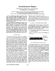
Abstract Field programmable gate arrays (FPGA) are widely used for their versatility and programmability in place of custom-designed circuits. Their flexibility comes at a cost of density: supporting programmable logic incurs a significant overhead in configuration logic and interconnect, relative to custom logic. The dominance and criticality of interconnect overhead in FPGAs gives a strong case for potential benefit from multi-layer integration. Migrating designs to new technologies often depends on good process characterization for static timing analysis and verification in synchronous designs. However, the asynchronous (delay-insensitive) design methodology eliminates the dependence on speculative timing analysis by tolerating arbitrary variation of gate delays. Our proposed 3D asynchronous FPGA (AFPGA) architecture is based on an existing 2D AFPGA. Pipelined AFPGAs have demonstrated a 3x improvement in performance over their synchronous counterparts. In this paper, we present the design of a 3D AFPGA, fabricated in MIT-LL’s 3D (3-tier) .18µm SOI technology. The logical resources for the 3D AFPGA were kept the same as the original 2D design, while the switch boxes were expanded with inter-layer channels for tier-to-tier routing. Our test chip demonstrates the viability and competitiveness of multi-layer asynchronous FPGA designs.
1
Introduction
Programmable circuits such as field programmable gate arrays (FPGA) are popular tools for prototyping arbitrary logic and replacing otherwise costly-to-design custom circuits. However, the versatility of FPGAs comes at the expense of reduced performance and increased energy compared to the equivalent functions implemented ∗ E-mail:
{fang,speng,ccl28,rajit}@csl.cornell.edu
as full-custom circuits. The configuration memory and programmable interconnects of FPGAs are the primary sources of area and performance overhead. Emerging multilayer integration technologies offer opportunities to increase logic density of circuits beyond the limits of featurescaling [13]. With multi-layer integration, planar device layers are stacked vertically, where adjacent device planes can be connected by short, inter-tier vias. Proposed approaches to leveraging multi-layer integration for FPGAs fall into one of the following categories: 1) 2D topology with stacked resources, 2) 3D topology of logic and interconnect. The first approach retains the 2D-array arrangement of tiles, but places the logic, routing interconnect, and configuration memory onto separate planes [14]. Moving the configuration memory onto a separate plane dramatically reduces the footprint area of the tile, resulting in increased logic density, shortening of interconnect wires, and consequently improved performance and energy efficiency. The second approach extends the FPGA array of resources (logic and interconnect) onto each new layer, so the logic area-density of a 3D topology scales directly with the number of device layers. Expanding to a 3D topology reduces the average interconnect distance from O(n1/2 ) to O(n1/3 ) where n is the number of blocks utilized in an FPGA [4]. For example, a square-tiled graph topology has four nearest neighbors per node, whereas a cube-tiled topology has six nearest neighbors per node. Increased connectivity of resources accommodates computation graphs with greater bisection bandwidth, utilizes fewer long-distance interconnects, and results in greater logic block utilization [1, 6, 20]. Our prototype FPGA uses the 3D topology by replicating resources uniformly onto each device layer. Another key characteristic of our 3D FPGA is that all computation and interconnect resources are self-timed, or asynchronous. Instead of using a global clock, asynchronous circuits use local handshakes to communicate data [17]. Asynchronous circuits are robust to delay mismatches and manufacturing variations, formally verifiable,
and modularly reusable and composable [8]. Asynchronous logic is purely data-driven, i.e. switching activity occurs only when there is computation to be done. Data-driven computation is very energy-efficient and saves energy akin to perfect clock-gating in synchronous designs. Asynchronous FPGAs (AFPGA) were originally proposed to eliminate the problems of global clock distribution, however, early efforts were inefficient at mapping asynchronous behavior onto synchronous FPGAs [10, 11]. More recent AFPGA architectures with pipelined asynchronous logic and interconnect resources have been shown to outperform current commercial synchronous FPGAs by over 3x [9, 22]. Our 3D FPGA design closely follows the design of such an existing AFPGA. Synthesis for AFPGAs has been shown to be effective in mapping sequential programs of computations onto the fine-grain pipelined building blocks that constitute the AFPGA architecture [19]. The input program is decomposed into concurrent dataflow graph nodes (reviewed in Section 2) and can be mapped onto the AFPGA architecture with conventional place-and-route tools such as vpr [5]. Likewise, the 3D AFPGA can use existing 3D place-androute tools such as tpr for mapping [2]. The key property that enables one to map concurrent dataflow graphs onto the AFPGA with varying interconnect pipeline depths is slack-elasticity [16]. The correctness and behavior of a slack-elastic concurrent program is invariant under different depths of pipelining on the edges of the computation graph (representing communication channels). Consequently, placement and routing of AFPGAs need not be timing driven, but mappings may be optimized by considering timing information. In the rest of this paper, we present the architecture and topology of the 3D AFPGA (Section 2), the MIT Lincoln Lab’s .18 µm 3D SOI process used to fabricate the prototype (Section 3), and an evaluation of the design (Section 4).
2
Logic block. The logic block remains unchanged from the baseline to the 3D design. Each logic block has one input and one output along each side (N,S,E,W) reaching the connection box (‘CB’ in Figure 2). The computation resources include: one function unit (4-input lookup table), one state unit (for state-holding feedback), one conditional unit (2-way merge and split), two output copy units (up to 4 copies), three local source units, and one local sink unit [22]. All of these units are implemented using finelypipelined asynchronous circuits [15]. Figure 3 shows the block diagram of the logic block’s resources and its internal connections. Our fabricated 3-tier prototype implements a subset of the full architecture: the state unit, conditional unit, and fast-carry chain are omitted (shown as shaded components in Figure 3). Without the omitted units, the 3-D AFPGA becomes simpler to implement and can still prototype most asynchronous logic. SB
SB
LB SB
SB
LB SB
LB SB
SB
LB SB
SB
Figure 1. Asynchronous FPGA island-style architecture
CB CB SB
LB
LB
FPGA Architecture
We first present the logic design of our AFPGA which includes the architecture description, and then we explain the physical design issues such as layout and process technology. The design of our 3-tier AFPGA is largely based on an existing single-tier AFPGA, referenced as the baseline design [22]. The original AFPGA architecture is arranged in a standard ‘island-style’ topology (shown in Figure 1), which is composed of logic blocks surrounded by programmable interconnect tracks. The logic block and interconnect resources were based on those found in the XilinxTM Virtex II FPGA [12]. Our 3-tier AFPGA extends the planar ‘islandstyle’ topology into 3-dimensions (shown in Figure 2) by adding inter-tier links to each switch box [20].
Figure 2. 3D FPGA island topology Interconnect. The baseline and the 3D design have nearly identical interconnect structures. All switch points in the interconnect contain pipeline buffers (Figure 4) so that routing a channel through more switches only increases the forward latency without degrading the throughput of inter-process communication. Each switch point contains two buffers to support two non-conflicting routes through
low−latency copies
N, E, S, W Nin
Input Buffer
N
Ein
Input Buffer
E
Sin
Input Buffer
S
Win
Input Buffer
Ci2
N, E, S, W, S1
(to north cell) Cout
N, E, S, W, S1 A B C D
N, E, S, W, S2 N, E, S, W, S3
W
Token Source
S1
Token Source
S2
Token Source
S3
Co2
Function Unit
N, E, S, W Cin (from south cell) X
State Unit N, E, S, W
G
N, E, S, W, S3
A B
N, E, S, W, S3
Input Pipelining and Routing
Conditional Unit
Y
Co2 X Y
A
Co2 X Z
B
Co2 X Y Z
Z
Pipelined Computation Block
Output Copy
Nout Eout Sout Wout
Token Sink Token Copy (pipelined)
Output Pipelining and Routing
Figure 3. Pipelined asynchronous FPGA logic block (shaded components omitted from 3D prototype)
each point. All five routing tracks only connect neighboring switch points; no “long tracks” bypass switches. Each switch box is linearly populated with five switch points. In the 3D prototype, we extended only one of the five switch points with inter-tier channels. This decision keeps the switch overhead (in configuration logic, area, energy, and performance) to a minimum while accommodating 3D mappings. In this topology, inter-tier communication must traverse at least two switches, one on the source tier and one on the destination tier. Alternative architectures may introduce programmable inter-tier switches directly into the logic block as a means of bypassing the global interconnect, reducing the inter-tier latency.
3
U
N,S,E,W,U,D E
buffer
S D
Physical Design
N,S,E,W,U,D
N W
architectures exploit multi-layer integration by separating configuration, logic, and routing resources onto different layers [6, 14]. In the future, we may see hybridization of these approaches. Configuration. Our configuration logic consists of a four-phase non-overlapping clocked serial scan-chain with a single input and a single output for verification. The logic block is configured by 96 bits, the 3D switch box is configured by 88 bits, and the connection box is configured by 20 bits. The scan chain itself was implemented with restoring logic as a conservative design choice, and consequently, accounted for a majority of the floorplan area.
buffer
Figure 4. 3D switch point schematic The architecture and topology we chose for the 3D AFPGA is a symmetric and uniform extension from a similar 2D AFPGA; it is just one of many possible architectures for 3D FPGAs [4]. For example, the Rothko 3D FPGA architecture proposes a less symmetric architecture where alternating tiers ‘flow’ in opposite directions [18]. Other
3.1
Technology
The 3D AFPGA is implemented in a three-tier, 180nm silicon-on-insulator (SOI) process developed at the Massachusetts Institute of Technology Lincoln Laboratory (MITLL). Each tier is a fully-depleted SOI wafer bonded to other tiers via a low-temperature wafer-wafer oxide bonding. Using SOI wafers provides two benefits: i) the insulator acts as an etch stop when stripping away the substrate [21], and ii) since the substrate is completely removed, the via holes do not need to be passivated (insulated) thereby reducing the via pitch [7]. Figure 5 shows a cross-section of the three-tiers after they have been bonded.
Tier 2 (middle) is flipped and bonded to the face of Tier 1 (bottom). Tier 3 (top) is flipped and bonded to the back of Tier 2.
2D switch 2D switch connect box X
3D switch 2D switch
connect box Y
output copy
function unit 4−LUT
output routing
input routing
2D switch
Figure 6. 3D AFPGA tile floorplan, corresponding to shaded area in Figure 1
Figure 5. Cross-section of three-tier 180nm SOI process. The inter-tier vias (vertical) etch through the wafers and terminate when a landing is reached. Each tier has three metal layers.
Each tier has three aluminum metal layers and tungstenfilled inter-tier vias. (Typical 180nm processes have six or more metal layers.) The inter-tier vias are 1.5µm wide, smaller than an SRAM cell in this technology, with a pitch of 5.6µm. Davis et al. have estimated the capacitance of these vias to be equivalent to that of a 8µm-20µm wire (the exact value depends on the coupling to the surrounding geometry) [7]. For comparison, the Rothko FPGA was fabricated with an older but similar SOI-based technology from Northeastern University, using wafer-scale transfers and assemblies (Kopin Technologies), featuring 6µm diameter vias [6]. Their inter-tier vias were etched (using inductively coupled plasma) through oxide and epoxy adhesive layers, lined in aluminum, but not tungsten-plugged due to temperature constraints. Wafer assembly technology has advanced significantly since solder bumps on die surfaces were used to assemble multi-chip modules (MCM) vertically [4]. As wafer alignment continues to improve, inter-tier via diameters will shrink, improving inter-tier connection density.
3.2
Layout
The full-custom layout for the prototype was completed on a short time budget of ten days. Consequently, density was not a primary objective of the physical design. No effort was spent to optimize the circuits for performance. We took some conservative measures in designing the circuits. Although the MITLL-SOI process featured 180nm transistors, we adhered to a 200nm (λ = .1µm) unit grid. For example, all local and global wiring conformed to a 12λ grid. Giving ourselves extra clearances in the wiring grid allowed the leaf cells to be assembled and wired rapidly. Minimal effort was spent in floorplanning the tile, shown in Figure 6. The blank regions of the floorplan contained only sparse local wires. This particular design was not hindered by the limited number (3) of metal layers per tier; a tile for a 2D AFPGA could look identical. The entire tile fit within a 450µm × 450µm square area. The majority of the layout was done using the magic editor. Since the tile design was nearly identical on all tiers, we were able to export copies of the same design onto different tiers by replicating the CIF output. The CIF copies were imported into Cadence where the inter-tier assembly was completed. A snapshot of the final layout is shown in Figure 7 as a 2 × 2 array. The fabricated prototype consists of a 10 × 10 × 3 array of tiles fitting in a 5mm x 5mm square area, and some smaller structures for testing.
Figure 7. 2x2 array of 3D AFPGA tiles. Each tier is identical and overlaps perfectly.
generator
connection box load
pipelined switch
pipelined 3D switch sink
sink critical handshake
pipelined switch
450 um data ack
critical handshake 1st hop fwd. latency
generator 2nd hop fwd. latency
a)
pipelined 3D switch b)
Figure 8. Schematic of simulation setup and measurements Table 1. Performance of various switch-points handshakes switch test forward latency (ps) throughput configuration 1st hop 2nd hop total (MHz) 1) 2D-to-2D, intra-tier 280 175 455 800 2) 3D-to-3D, intra-tier 285 190 475 675 3) 3D-to-3D, inter-tier 260 190 450 730
4
Evaluation
In this section, we present some measurements from analog simulations of the new circuits in the 3D AFPGA prototype. The only change in the physical design (from the original 2D AFPGA) was introduction of 3D switches, which have greater internal capacitance due to the the increased number of pass-gates. In Table 1, we compare the throughput and forward latencies of communicating data between 1) two laterally neighboring 2D switch points (Figure 8a), 2) two laterally neighboring 3D switch points (Figure 8a), 3) two vertically neighboring 3D switch points (Figure 8b). In all cases, the data communication traversed two switches (2-hop). Circuit extraction was done using CadenceTM and a design kit supplied by NCSU. Analog simulations were run using SpectraTM , including the configuration scan-in phase. The throughput is measured as the peak frequency of the critical handshake, while the forward latencies are measured as the delay through each switch, as shown in Figure 8a. To estimate the latency of data through N switches, one simply takes the sum of 1st-hop latencies in Table 1, because the 2nd-hop latencies do not bear the actual load of the interconnect. These measurements provide an idea of the relative performance cost of mapping channel communications through the inter-tier routing resources. The difference between 1) and 2) shows the performance overhead in increasing the number of channels that may connect to the inputs and outputs of the switch points buffer.
The additional delay is attributed to the increase in capacitance in the surrounding pass-gates. When routing only laterally within a tier, the 3D track (only one per box) should be routed with lowest priority because it is the slowest. The 3D inter-tier performance gives an interesting comparison with the performance of the 2D intra-tier communication. The hop latency through the inter-tier via (260 ps) is faster than the intra-tier latency though the 2D switch (285 ps)1 . This is attributed to a trade-off between a long wire load and the capacitive load of the inter-tier via. The intra-tier connection between is also loaded with pass-gates from the connection box between each switch, whereas the inter-tier connection bears no such load (Figure 8b). In our measurements, only the first hop of the inter-tier case bears the load of the inter-tier via, which accounts for its latency. The interconnect handshakes are usually not among the critical path for the peak performance of AFPGAs; the critical path for our AFPGA architecture is the functional unit [19]. With a 2D-to-2D interconnect frequency of 800 MHz, one might expect a typical performance of 600 to 700 MHz. Thus, the reduced performance of the 3D switches may not severely impact the throughput of feed-forward computations routed through the 3D switches. Since AFPGAs already exhibit high performance through pipelined interconnects, we do not expect to see the kind of speed gains anticipated with synchronous FPGAs, which benefit more from shorter critical paths through 1 The supplied technology file gave no capacitance values for the intertier vias, thus the inter-tier latency is optimistic.
unpipelined interconnect. Recall that routing through pipelined switches only increases forward latency without degrading the interconnect throughput. 30% to 40% reductions in critical path delays in synchronous FPGAs still do not achieve the throughputs obtained by 2D pipelined AFPGAs [2, 3]. However, asynchronous computations with loop-carried dependencies (cycles) are likely to benefit from 3D synthesis where shortening critical loops through the interconnect decreases loop forward latencies [19]. The energy reduced by utilizing the third dimension is expected to be comparable to those projected in synchronous FPGAs, by reducing total interconnect length used for routing [3, 14].
5
Lessons
Rapidly implementing a 3D AFPGA been an enlightening experience. The fact that our design was self-timed by construction saved a significant amount of effort that is normally required for timing analysis. Timing characterization with an experimental and unfamiliar 3D technology would have been, at best, speculative. Some conservative design choices facilitated timely assembly of a large-scale full-custom design. Our simulations may offer some intuition for the cost of using inter-tier vias. Although the size of vias have shrunk significantly with each generation of 3D integration, the cost is certainly not small enough to use them gratuitously without incurring some performance costs. Poor partitioning of circuits onto different tiers can still result in significant performance loss. For our 3D AFPGA design, converting only one switch per tile into a 3D switch severely underutilized the potential of multi-layer integration. Since the size of the inter-tier via was comparable to that of an SRAM cell, it would’ve been easy to alter the architecture to support inter-tier connections at other sites besides the switch boxes. In our particular design, the inter-tier vias incurred only a tiny area cost relative the other routing and logic resources.
6
Summary
We have proposed a 3D architecture for asynchronous FPGAs (AFPGA) and implemented a prototype, using a 3tier 180nm SOI process. With minimal modifications to an existing 2D AFPGA, we have completed an unoptimized physical design of an entire 3D AFPGA. We have also measured the impact of inter-tier vias on performance of the switch points in the 3D AFPGA interconnect. Simulations of the new circuits (and benchmarks of the baseline 2D AFPGA) suggest that this prototype will operate typically over 600 MHz. The completion of this project is a testa-
ment to the performance and robustness of asynchronous circuit design. This project demonstrates that 3D integration is a promising target technology for asynchronous FPGAs. As multi-layer technologies continue to improve, one can expect the density, performance, and efficiency of AFPGAs to follow.
Acknowledgments We would like to thank MIT Lincoln Labs for the opportunity to undertake this project.
References [1] Cristinel Ababei, Pongstorn Maidee, and Kia Bazargan. Exploring potential benefits of 3D FPGA integration. In 14th International Conference on Field Programmable Logic and Applications (FPL 2004), pages 874–880, 2004. [2] Cristinel Ababei, Hushrav Mogal, and Kia Bazargan. Three-dimensional place and route for FPGAs. In ASP-DAC ’05: Proceedings of the 2005 Conference on Asia South Pacific Design Automation, pages 773– 778, 2005. [3] M. Alexander, J. Cohoon, J. Colflesh, J. Karro, E. Peters, and G. Robins. Placement and routing for threedimensional FPGAs. In Fourth Canadian Workshop on Field-Programmable Devices, pages 11–18, May 1996. [4] M. J. Alexander, J. P. Cohoon, J. L. Coleflesh, J. Karro, and G. Robins. Three-dimensional fieldprogrammable gate arrays. In Proc. IEEE International ASIC Conference, pages 253–256, Austin, TX, September 1995. [5] V. Betz and J. Rose. VPR: A new packing, placement, and routing tool for FPGA research. In Proc. International Workshop on Field Programmable Logic and Applications, 1997. [6] Silviu Chiricescu, Miriam Leeser, and M. Michael Vai. Design and analysis of a dynamically reconfigurable three-dimensional FPGA. IEEE Trans. Very Large Scale Integr. Syst., 9(1):186–197, 2001. [7] W. Rhett Davis, John Wilson, Stephen Mick, Jian Xu, Hao Hua, Christopher Mineo, Ambarish M. Sule, Michael Steer, and Paul D. Franzon. Demystifying 3D ICs: The pros and cons of going vertical. IEEE Design and Test, 22(6):498–510, 2005.
[8] K. Emerson. Asynchronous design – an interesting alternative. In Proc. International Conference on VLSI Design, 1997. [9] David Fang, John Teifel, and Rajit Manohar. A high-performance asynchronous FPGA: Test results. In Proc. of the 13th Annual IEEE Symposium on Field-Programmable Custom Computing Machines (FCCM’05), pages 271–272, 2005. [10] S. Hauck, G. Borriello, S. Burns, and C. Ebeling. Montage: An FPGA for synchronous and asynchronous circuits. In FPL, Vienna, August 1992. [11] S. Hauck, S. Burns, G. Borriello, and C. Ebeling. An FPGA for implementing asynchronous circuits. IEEE Design and Test of Computers, 11(3):60–69, 1994. [12] Xilinx Inc. VirtexTM 2.5V field programmable gate arrays. Xilinx Data Sheet, 2002. [13] S.J. Souri K. Banerjee, P. Kapur, and K.C. Saraswat. 3-D ICs: a novel chip design for improving deep-submicrometer interconnect performance and systems-on-chip integration. Proceedings of the IEEE, 89(5), 2001. [14] Mingjie Lin, Abbas El Gamal, Yi-Chang Lu, and Simon Wong. Performance benefits of monolithically stacked 3D-FPGA. In Proc. Internation Symposium on Field Programmable Gate Arrays (FPGA ’06), pages 113–122, 2006. [15] A. Lines. Pipelined asynchronous circuits. Master’s thesis, California Institute of Technology, 1995. [16] Rajit Manohar and Alain J. Martin. Slack elasticity in concurrent computing. In Johan Jeuring, editor, International Conference on the Mathematics of Program Construction, volume 1422 of Lecture Notes in Computer Science, pages 272–285. Springer-Verlag, July 1998. [17] Alain J. Martin. The limitations to delay-insensitivity in asynchronous circuits. In Proc. Conference on Advanced Research in VLSI, 1990. [18] W. Meleis, M. Leeser, P. Zavracky, and M. Vai. Architectural design of a three dimensional FPGA, 1997. [19] Song Peng, David Fang, John Teifel, and Rajit Manohar. Automated synthesis for asynchronous FPGAs. In Proc. 2005 ACM/SIGDA 13th International Symposium on Field-Programmable Gate Arrays (FPGA ’05), pages 163–173, 2005.
[20] Arifur Rahman, Shamik Das, Anantha P. Chandrakasan, and Rafael Reif. Wiring requirement and three-dimensional integration technology for field programmable gate arrays. IEEE Trans. Very Large Scale Integr. Syst., 11(1):44–54, 2003. [21] V. Suntharalingam, R. Berger, J. A. Burns, and et al. Megapixel CMOS image sensor fabricated in threedimensional integrated circuit technology. In IEEE Solid-State Circuits Conference, Digest of Technical Papers, volume 1, pages 356–357, February 2005. [22] J. Teifel and R. Manohar. Highly pipelined asynchronous FPGAs. In Proceedings of International Symposium on Field Programmable Gate Arrays, February 2004.