sonal workspaces, as well as a shared workspace with a dedicated ..... Figure 16 shows the configuration of the 2D server which consists of a main thread, a.
A 2D-3D Integrated Tabletop Environment for Multi-user Collaboration Kousuke Nakashima†, Takashi Machida†‡, Kiyoshi Kiyokawa†‡ and Haruo Takemura†‡ †Graduate School of Information Science, Osaka University ‡Cybermedia Center, Osaka University Toyonaka Educational Research Center 1-32 Machikaneyama, Toyonaka, Osaka 560-0043, Japan email: {machida, kiyo, takemura}@ime.cmc.osaka-u.ac.jp Abstract This paper proposes a novel tabletop display system for natural communication and flexible information sharing. The proposed system is specifically designed to integrate two-dimensional (2D) and three-dimensional (3D) user interfaces by using a multi-user stereoscopic display, IllusionHole. The proposed system takes awareness into consideration and provides both 2D and 3D information and user interfaces. On
1
the display, a number of standard Windows desktop environments are provided as personal workspaces, as well as a shared workspace with a dedicated graphical user interface. In the personal workspaces, users can simultaneously access existing applications and data, and exchange information between personal and shared workspaces. In this way, the proposed system can seamlessly integrate personal, shared, 2D and 3D workspaces with conventional user interfaces and effectively support communication and information sharing. To demonstrate the capabilities of the proposed display system, a modeling application was implemented. A preliminary experiment confirmed the effectiveness of this system.
Keywords: Collaboration, Tabletop Interface, 3D User Interface, Face-to-face communication
2
Introduction This paper proposes a novel tabletop display system for natural communication and flexible information sharing. The proposed system is specifically designed for awareness support and integration of two-dimensional (2D) and three-dimensional (3D) user interfaces. Figure 1 shows the proposed system in use. Human-to-human communication and information sharing are crucial for cooperative work. Information sharing means that information in a collaborative workspace is properly seen and manipulated by the participants. Collaboration is promoted by discussing such shared information. There are many examples of information that can be shared, including drawings, documents, maps, and maquettes. To establish an effective cooperative workspace, the following issues need to be considered. • Workspace layout for awareness support. • Compatibility with a conventional desktop environment. • Support of various kinds of information.
The first issue is the workspace layout. To share information in cooperative work, a table, white board, and large screen display are typically used. When the shared workspace is on a wall (e.g., a white board and a large screen), the participants cannot see each other’s face and gestures while paying attention to the shared information on the wall. Conversely, they cannot see the information on the wall while looking at each other. However, when the 3
participants sit around a table facing each other, it is easy to communicate by exchanging non-verbal communication cues such as facial expressions, poses, gestures and viewing directions. These cues play a big role in communication and attract attention. Paying attention to non- verbal information is referred to as “awareness.” To raise awareness, it is useful to use a table-type screen [1, 2, 3]. The second issue is compatibility with a conventional desktop environment. When information is shared on the screen, it is important that the entire workspace is divided into a shared workspace and a number of personal workspaces so that information in the personal workspace can be presented in the shared workspace and the shared information can be manipulated by any participant cooperatively. The shared workspace should always be accessible to all users to encourage discussion in collaboration. On the other hand, personal workspaces placed near the shared workspace are said to have an important role in terms of independent activity and collaboration efficiency [2]. In addition, the personal workspace should be provided in such a way that each participant can easily access and process information in it. In a typical meeting, where each participant brings his or her own laptop computer, only a single computer screen is shared at a time and participants need to switch screens frequently. But, each participant knows how to use his or her own personal workspace. To provide a better workspace, several studies have developed a collaboration system that seamlessly integrates a conventional desktop graphical user interface (GUI) environment with a shared screen [1, 2, 4, 5]. Some studies have developed a set of dedicated interaction techniques for shared information on a table [6]. 4
The third issue is about the variation of shared information. Shared information can be either 2D or 3D, according to the collaboration task. To support 3D information, a collaborative workspace is expected to present 3D (stereoscopic) images correctly to every participant so that the entity appears at a single location. Some studies try to integrate conventional computer environments into 3D workspaces using augmented reality or mixed reality techniques [7, 8]. This paper proposes a new cooperative tabletop system, which integrates four types of workspaces: 2D, 3D, personal and shared. In the following section, related work is briefly introduced. Then the characteristics and functions of the proposed system are described. Next, the implementation details are described, followed by a modeling application. Finally, a preliminary experiment is discussed.
Related work Since the early 1980’s, Computer Supported Cooperative Work (CSCW) and groupware have been intensively investigated [9]. A typical configuration for early collaborative systems used several small screens for each participant and a single shared wall screen. In such a system, every participant is able to observe and operate the shared wall screen. CoLab [4] provided each participant with a Xerox workstation, which was connected to each of the others via a network. A large touch-sensitive screen was provided as a shared screen, which was accessible from any Xerox workstation. CaptureLab [5] provided each participant with
5
a Macintosh computer, and the screen of another Macintosh computer dedicated for information sharing was provided by using a rear projector. In this system, each participant is able to operate the shared screen by connecting his or her own keyboard and mouse to the shared computer by simply pushing a power button on the keyboard. One of the advantages of these systems is that an everyday computing environment can be introduced into a group discussion. Thus, a variety of existing application software can be used. In addition, there is no need for training or the transfer of skills. However, it is difficult to support multiple users’ simultaneous input with these systems, as they only switch standard desktop environments that were originally designed for a single user. Augmented Surfaces [1] and i-LAND [2] support the independent activities of multiple users on a shared screen. Augmented Surfaces is a collaborative workspace composed of personal laptop computers and a few shared screens. Augmented Surfaces tries to remove the barriers between screens. In this environment, information can be dragged beyond screen edges and transferred to another screen by a drag-and-drop operation. In this system, several personal desktop environments, a tabletop shared screen (InfoTable), and a shared wall screen (InfoWall) are seamlessly integrated. The i-LAND project embeds computing facilities into office furniture to facilitate computer-supported casual group discussion. For example, a participant can share and modify information on a shared wall screen, DynaWall, by using computer-embedded chairs, CommChairs. These systems allow the simultaneous input of multiple users on a screen. This is made possible by a specially designed underlying event-handling layer implemented in Java [1] or BEACH [2]. In this sense, these 6
environments are less compatible with existing computing environments. Our system supports both conventional computing environments and information sharing with multi-user input capability. To support awareness and exchange non-verbal communication cues, a tabletop screen is preferable to a wall screen. Kiyokawa et al. [10] explored how the separation between the task space and the communication space affects collaboration. They found that seeing the partner all of the time as well as sharing information motivated the participants to involve each other by pointing gestures and initiatory utterances. Participants also made fewer clarifications and laughed more. In this sense, the InfoTable of Augmented Surfaces and the InteracTable of i-Land have a better layout compared to CoLab and CaptureLab. Unlike a wall screen, however, orientation becomes a problem with a tabletop screen. 2D information needs to be rotated properly with a tabletop system. Vernier et al. [11] proposed visualization techniques considering the round shape of a table. DiamondSpin [6] is a Java toolkit for developing a multi-user tabletop application. DiamondSpin supports multi-user input and arbitrary rotation of the GUI (graphical user interface) component. Our system also supports these features. Because 3D information has already become a common medium of personal computers, a collaborative system is expected to handle 3D information as well. To observe and manipulate 3D information from each user’s perspective in a collaborative setup, a head mounted display (HMD) is widely used. EMMIE [7] and MagicMeeting [8] are examples of HMDbased collaborative systems using augmented reality (AR) technology. In EMMIE, conven7
tional computing environments such as laptop computers can be used, and information can be moved between a 2D computer screen and a 3D space using a 3D pointing device. In MagicMeeting, a conventional Windows desktop environment is overlaid in the real environment as a textured rectangle using a video see-through AR technique. There have been several attempts to integrate conventional computing environments and a 3D environment [12, 13, 14]. However, the HMD severely restricts peripheral vision, which is important for observing other participants’ faces and gestures [15]. Thus, there have been a number of stereoscopic projection displays for multi-user observation, which generally provide a better peripheral view compared to an HMD [16, 17, 18]. In our system, the IllusionHole display [18] is employed to provide a 3D shared space to participants.
The cooperative tabletop system In this section, an overview of the proposed system is described. First, the display design to support 2D and 3D information is given. Then, the tabletop environment that supports both a conventional Windows desktop environment as a personal workspace and a shared workspace is explained.
2D-3D display system design Our system consists of IllusionHole [18] to provide a 3D cooperative workspace and another overhead projector to display a 2D workspace onto a mask panel of IllusionHole, as 8
shown in Figure 2(a). A pair of stereoscopic images is displayed using the 60-inch IllusionHole with a hole diameter of 26 cm. Since IllusionHole’s mask panel usually shows a pair of stereoscopic images exclusively to one user and hides them from other users, multiple (practically, up to four) users can simultaneously observe the same 3D scene from their own viewpoints through a pair of polarized glasses with a head-tracking facility. Unlike the conventional IllusionHole, our system utilizes the mask panel of IllusionHole for projection of a 2D workspace. Note that a pair of polarized glasses is advantageous over a head mounted display (HMD) in terms of easy attachment and peripheral vision. Peripheral vision is important to observe other participants’ faces and gestures [15]. The proposed system is designed to display both 2D and 3D information. In a conventional environment, if different devices are provided for 2D and 3D environments, users need to switch devices repeatedly, which causes physical and cognitive burdens. A stick mouse (Figure 2(b)), which is seamlessly available in both 2D and 3D workspaces, is then provided in the proposed system. The stick mouse works as a normal mouse when it is manipulated on the mask panel in 2D mode, in which a 2D pointer appears (see Figure 3(a)). On the other hand, when it is manipulated inside a cylinder-shaped 3D volume above the mask hole, it works as a 3D pointing device (3D mode) using a Polhemus tracker with six degree-of-freedom (6 DOF) (see Figure 3(b)). In the 3D mode, an arrow-headed 3D cursor appears at the tip of the stick in the 3D workspace. An operation plate (Figure 2(c)) is a plastic board with a Polhemus tracker, with which a variety of 2D-3D coordinated functions can be performed. The operation plate is con9
sidered a second, independent 2D workspace, and it also acts as a bridge between 2D and 3D workspaces. For example, a user can invoke and operate a 2D hierarchical menu on the operation plate, or select a 2D cross section of a 3D model for 2D editing at an arbitrary orientation by placing the board inside the model, or scoop a 3D object to move to the 2D workspace like a palette. The operation plate is similar to Transparent Props, proposed by Schmalstieg et al. [21]. One important advantage of the operation plate is that the 2D image is directly projected and seen on the panel surface so that every user in a multi-user setup can see the 2D image without distortion. For a 2D image on the operation plate, the projection frustum is precisely adjusted to the real frustum defined by the overhead projector and the mask panel (see Figure 4). The 2D image to be shown on the operation plate is rendered as a virtual plate in space at the position and orientation of the actual operation plate and is transformed with this perspective projection. As a result, any 2D image is projected onto the operation plate without distortion.
Tabletop environment Figure 1(a) shows the tabletop environment in use. The tabletop environment is composed of a few standard Windows desktop environments (personal workspaces) and a shared workspace. A standard Windows desktop is provided to each participant as a scalable, movable GUI component. On the other hand, a dedicated GUI (tabletop GUI) is provided as the shared workspace. In the following, we describe the characteristics of the tabletop environ-
10
ment.
Tabletop GUI The tabletop GUI is a conventional Windows desktop environment consisting of a mouse cursor, pop-up menu and desktop environment (Figure 1(b)). A stick mouse and a keyboard are used as input devices. Each mouse displays a corresponding mouse pointer. A popup menu appears if a user clicks the right button of the mouse. Since this mechanism is realized by a standard Virtual Network Computing (VNC) protocol, participants can bring their own Windows environments into the tabletop GUI to utilize existing applications and data. In this way, the tabletop environment seamlessly integrates shared and personal workspaces.
Simultaneous input In this system, every mouse and keyboard is connected to a single computer via a USB connection. Each input device and event is recognized and processed independently using raw Windows APIs. So, users of this system can use an arbitrary number (up to 127) of mice and keyboards independently. That is, multiple users can simultaneously manipulate a GUI on the tabletop environment. For example, multiple users can use their pop-up menus and desktop environments in parallel by maneuvering the mice and keyboards.
11
Adaptive mouse coordinate system When a user holds a mouse, he or she tends to maintain the relative position and orientation between his or her body and the mouse, regardless of his or her position. In a tabletop user interface, it becomes difficult to operate a mouse when the direction of the mouse is wrong side up. To solve this problem, it is necessary to rotate the mouse coordinate system according to the user’s standing position so that he or she can move the mouse pointer easily. In this system, the user’s eye position is used to rotate the mouse coordinate system based on the following two different policies. • Circle The mouse coordinate system is rotated so that its y-axis becomes parallel to a line connecting the user’s position and the center of the screen (Figure 5(a)). In this case, the mouse coordinate system rotates continuously. • Partition The entire screen is partitioned into four areas according to the screen edges. The mouse coordinate system is rotated discretely so that the x- and y-axes are parallel to the screen edges (Figure 5(b)).
In the tabletop environment, the mouse pointer and GUI components such as pop-up menus are dynamically rotated according to the corresponding user’s standing position. This function helps users easily operate the tabletop GUI and distinguish right mouse pointers and 12
GUI components.
Desktop environments The desktop environment in the tabletop environment is not only used as a conventional personal space, but users can also use the desktop environment as a kind of shared workspace. That is, any user can operate any desktop environment and multiple users can share a single desktop environment. Figure 6 shows an example operation. In Figure 6(left), a user is operating a desktop environment with his mouse pointer in its boundary. In Figure 6(middle), the mouse pointer has left the desktop environment and is moving to the other desktop environment. In Figure 6(right), the user is now operating the other desktop environment. Based on the entry of the mouse pointer, an appropriate keyboard is chosen for key events. In this way, users can use their favorite applications simultaneously and seamlessly without the need for switching of input devices and computer screens.
Moving, rotating and scaling of a desktop environment Manipulation of a desktop environment in the tabletop GUI is similar to that of a single window in a standard GUI. Users can move, scale, and even rotate the desktop environment in the tabletop environment (Figure 7). The margin (border area) is set around each desktop environment. When the margin is dragged with the left mouse button, the desktop environment is moved in the tabletop environment. To see or to show information in a desktop environment, users can simply move it closer to the observer. When the margin is dragged 13
with the right button, the desktop environment is rotated around its center. This function is helpful in reading information in a desktop environment. When the mouse wheel is scrolled, the desktop environment is scaled up or down. Using this function, a desktop environment of interest can be enlarged while an unnecessary one can be shrunk temporarily. An overlapped desktop environment can be moved to the front by clicking its margin (see Figure 8). A desktop environment can be hidden by using a pop-up menu.
Information transfer from desktop to tabletop Information in a desktop environment (personal workspace) can be transferred to the tabletop environment (shared workspace). If a user copies a file in a desktop environment, the file is copied to a virtual clipboard of the tabletop environment. Note that an arbitrary file type is supported and multiple files can be copied at a time. For example, a file containing 3D geometry data can be copied from a desktop environment, and then shown at the center of the tabletop environment as a stereo image using IllusionHole (Figure 9). First, the 3D object file is selected from folders on the desktop and copied. Then, the user moves the mouse pointer to the outside of the desktop environment and pastes the file by using a pop-up menu. He or she can see the 3D object stereoscopically by the pasting operation. In this way, desktop environments are seamlessly integrated into the shared space. As another method of information transfer, the drag-and-drop feature is under development.
14
Menu operation on the operation plate Normally, a user needs to place his or her mouse pointer on the screen to use a pop-up menu. But this is inconvenient when the user is working in the 3D workspace. So another way of using a pop-up menu is provided using the operation plate (Figure 10(a)). In this case, the tip of the stick mouse is used to select the menu item. A mouse pointer is shown at the foot of the perpendicular line connecting the surface and the mouse tip. As a normal pop-up menu on the mask panel, the mouse pointer can be used to select a menu item (Figure 10(b)).
Implementation In this section, implementation details of the proposed system, specifically hardware and software configurations, are described.
Hardware configuration Figure 11 shows the system configuration of the proposed system. The proposed system consists of a 3D server, a 2D server and a number of desktop PCs. The 3D server (Pentium 4 2.4 GHz, 512 Mbytes memory, nVidia GeForce4 4600) renders a stereoscopic 3D scene and controls Polhemus Fastrak via a RS-232C that tracks the 6-DOF information of the polarized glasses, stick mice, and operation plate. A 2D user interface is shown on the mask panel and on the operation plates projected from an overhead projector placed above the IllusionHole. The 2D server (Pentium 4 3.06 GHz, 1 Gbyte memory, nVidia GeForce4 4600) renders 2D 15
images and controls the stick mice and keyboards via a USB. Using raw Windows APIs, an arbitrary number (up to 127) of USB mice and keyboards can be connected to the 2D server and independently controlled. Tracking information is sent from the 3D server to the 2D server, while the mice information is sent in the opposite direction to maintain the consistency.
Software configuration The prototype system can handle multiple USB mice with a single 2D server by using raw Windows APIs. Multiple keyboards are also available with the 2D server. All of the mouse and keyboard events received by the OpenGL window process need to be dispatched to the correct VNC client (and a VNC server) (See Figure 12). Since the OpenGL window process knows all clients’ information, it is easy to implement a direct manipulation interface for data exchange among personal workspaces [22]. In the proposed system, a 3D server, a 2D server and the user’s desktop client communicate with each other on the local area network. Figure 13 shows the processes on each computer. The 3D server executes the tracker server and 3D server processes. The 2D server executes the 2D server processes. Each desktop client executes an extended VNC server process. In the following, each process is described in detail.
16
Tracker server configuration Figure 14 shows the tracking processes on the tracker server. The tracking processes consist of a tracker thread, a connection thread and a client thread.
Tracker thread
The tracker thread controls the 3D tracker and Polhemus Fastrak, and
receives 6-DOF information (position and orientation). Polhemus Fastrak is controlled through a RS-232C serial connection, and the 6-DOF information is transmitted asynchronously.
Connection thread
The connection thread waits for a connection request from the 2D and
3D servers. Because the 2D and 3D servers require 6-DOF information, they are connected to the tracker server as clients.
Client thread
The client thread receive 6-DOF information from the tracker thread and
sends it to the 2D and 3D servers. Two client threads are activated for the 2D and 3D servers.
3D server configuration Figure 15 shows the configuration of the 3D server. The 3D server consists of a tracker thread, a 2D thread and a main thread.
Tracker thread
The tracker thread receives 6-DOF information from the tracker server.
The 6-DOF information (position and orientation) is asynchronously updated. On the 3D
17
server, polarized glasses and the stick mouse require position and orientation information.
2D thread
The 2D thread receives updated information of 3D objects from the 2D server.
The main thread updates the scene graph and the vertices of 3D objects based on the updated information and generates the 3D images.
Main thread
In the main thread, 3D images are rendered and displayed on IllusionHole.
At first, each user’s eye position is decided based on the position of the polarized glasses. Then, the scene graph and the vertices of the 3D objects which are rendered as 3D images on IllusionHole are updated. The updated information is received in the 2D thread. 3D images are rendered based on the viewing frustum and the perspective projection (See Figure 4). The projection direction is orthogonal to the screen surface of IllusionHole from the eye position. The height of the clipping surface is appropriately set by considering the position of the 3D objects. Users can see the 3D objects stereoscopically by rendering the objects using the perspective projection with respect to both left and right eyes.
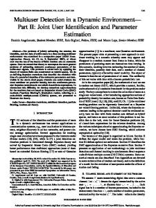
2D server configuration The 2D server is a key component in the proposed system. The 2D server manages the overall processes of the tabletop environment. Specifically, the tabletop GUI, the modeling application and the operation and rendering of the desktop environment are managed. Figure 16 shows the configuration of the 2D server which consists of a main thread, a tracker thread, an extended VNC thread, a main window, an application window, and an 18
extended VNC client window. All windows work together by notification of the Window messaging mechanism. Note that the number of pairs of the extended VNC client threads and the extended VNC client windows are equal to the number of desktop computers.
Main thread
The main thread displays the image of the tabletop environment to the client
region in the main window. The rendering image is the tabletop GUI, including the mouse pointer, the menu and the desktop environment, and the modeling application window. The position and orientation of the tabletop GUI image changes according to the position and orientation of the user. In the case of displaying the tabletop GUI and the modeling application window images on the mask panel, the images are rendered with an orthogonal projection from the head of the user toward the mask panel. In the case of rendering the images on the operation plate, it is necessary to render the images with the perspective projection to project a non-distorted image on the plate at an arbitrary position (See Figure 4). First, the position of the projector is set as the eye position of the viewing frustum, and the projection direction is the vertical falling downward. Then, the back clipping surface is set at the position of the mask panel, and the front clipping surface is set at an appropriate height. Finally, a virtual object representing the operation plate is placed at the position and orientation of the plate and rendered with the perspective projection. As the result, a non-distorted image is displayed on the plate regardless of its position and orientation.
19
Main window
In the main window, there are processes for the mice and keyboards, up-
dates of desktop textures and file copy notification. • Mice and keyboards. In the proposed system, Windows’ RawInput API is used to realize both mouse and keyboard inputs simultaneously. The mice and keyboards are set as RawInput devices and recognized as different devices. This API enables users to identify any input device when multiple users use multiple input devices. In addition, it is necessary to transform the coordinate systems of each mouse as each is rotated according to each user’s eye position in the tabletop environment. After the input device is identified, the subject of its input event is determined. The subject of an input event can be a menu, the modeling application and the desktop environment. When the input device being used is a keyboard, its subject is always the desktop environment. When a menu is the subject, the operation mode becomes a menu mode. If the mode changes to the modeling application, that information is notified to the application window. When the modeling application is the subject, the mouse information is notified to the application window. In the desktop environment, the operation mode is determined based on the location of the 2D mouse pointer. If the mouse pointer is on the margin of the desktop environment, mouse events are used to select, translate, rotate, and scale the desk20
top environment. If the mouse pointer is inside the desktop environment, the mouse events are transferred to the desktop environment. In this case, input messages of the mice and keyboards with RawInput API are translated to the standard mouse and keyboard messages so that they can be handled with the Windows messaging mechanism. Then, the coordinates of the mice are transformed to the desktop coordinates, and the messages are notified to the extended VNC client window. • Update of desktop texture. The desktop image is updated as a bitmap in an extended VNC client window. However, the bitmap is not displayed because the extended VNC client window is a dummy. The bitmap is displayed on the main window as a texture-mapped rectangle. The desktop texture is updated when the extended VNC client window notifies the image update. • File copy notification. When a file is copied in the desktop environment, that information is notified from the extended VNC client window. In addition, if the file format is available in the modeling application (e.g., .OBJ or .MTL), the notification message is forwarded to the application window. The application window selects the copied file automatically by the notification message when a new 3D model is loaded.
21
Application window
In the application window, the process of the modeling application
is executed. First, the input information of the mice and notification of a mode change from the main window, and 6-DOF information from the tracker thread are acquired. Then, the operation in the 2D and 3D workspaces is executed based on this information. As a result, the scene graph and vertex data of 3D objects are updated and sent to the 3D server. Note that the application window is a dummy and the application image is displayed on the main window.
Extended VNC client thread
The extended VNC client thread receives information from
the extended VNC server. This information consists of the update image and copied files of each user’s desktop environment. When the information is received, notification is sent to the extended VNC client window.
Extended VNC client window
The extended VNC client window executes the processes
relevant to the desktop environment. Such processes include sending information of the mice and keyboards to the extended VNC server, decoding and image updating of information received from the extended VNC server, and file copying. • Sending information of the mice and keyboards. Input information of mice and keyboards, notified from the main window, is sent to the extended VNC server as input events to the desktop environment. • Decoding and updating image. 22
When the extended VNC client thread receives an image, the thread notifies the extended VNC client window. Here, it is necessary to decode the received image because the image is encoded based on the VNC protocol. The decoded image is used to update the desktop bitmap. Note that the extended VNC client window is a dummy, and the desktop bitmap is displayed as a texture-mapped rectangle on the main window. After the extended VNC client window updates the image, the request for the image update is sent to the extended VNC server. Through these processes, the desktop bitmap is always kept up-to-date. • File copying. If a file is copied on the desktop environment, the extended VNC client thread notifies the file path name. The extended VNC client window requests the file sending. The received file is stored in a folder which is shared by the 2D and 3D server computers. Information of a copied file is notified to the main window.
Tracker thread The tracker thread receives 6-DOF information asynchronously from the tracker server. The 2D server needs the position and orientation of the polarized glasses, the stick mouse, and the operation plate.
23
Extended VNC server configuration The software architecture for the personal workspace is shown in Figure 17. VNC technology [19, 20] is employed to realize the feature. Although VNC was originally developed for remote control of a computer, it can be applied for co-located collaboration [8]. An OpenGL window process and VNC client processes are executed on the 2D server. When the OpenGL window process accepts a connection request from a VNC server that runs on a remote computer, a new VNC client is invoked. The VNC client sends the OpenGL window process a remote desktop image received from the VNC server. The image is then transformed properly and rendered on the mask panel as a texture-mapped rectangle. The following functions of VNC are specifically modified and extended. • Multi-server and parallel processing. In our system, each desktop environment is available independently. To realize this, the VNC viewer (client) has to handle multiple VNC servers. So, the main functions of the VNC viewer, including communication, image processing, and decoding, are modified to use multiple threads. The mice and keyboard events and update requests are sent to the corresponding desktop environment appropriately. • Translation from Windows DIB to OpenGL texture. A VNC viewer of Ultr@VNC [20] outputs bitmap images (Windows DIB) of a desktop environment using the Windows graphics device interface (GDI). On the other
24
hand, our system needs to move, rotate and scale the desktop image freely. This feature is realized by using the texture mapping function of the OpenGL API. Only the update portions of the desktop image are sent to the OpenGL pipeline in order to reduce the graphics bandwidth. • Transfer files using the clipboard. In a Windows environment, copied or cut data are automatically stored in a clipboard, which is a storage area any application can access. The VNC server was modified to watch the clipboard and transfer copied filenames to the VNC viewer.
Desktop thread
The desktop thread acquires the desktop image from the desktop buffer.
Because the extended VNC server uses the purpose-built video driver and not Windows’ GDI, fast capturing of the desktop environment of Windows is realized.
Client thread
The client thread sends information that includes the updated image, up-
dated contents of the clipboard, and copied file to the extended VNC client. Depending on the information, the following process is executed. • Acquiring and encoding updated image. The image which is updated by requests and input from the client update thread is acquired in the desktop thread. The acquired image is encoded and sent to the extended VNC client.
25
• Update of monitored clipboard. The client thread monitors the update of the clipboard. When a user operates the file copy, the file path name is copied in the clipboard. Such information is sent to the extended VNC client. • Copy of sent files. When the requests for file sending are conveyed from the client update thread, the file is copied and sent to the extended VNC client.
Client update thread
The client update thread receives information that includes the input
contents of the mice and keyboards, and notification of requests for updating images and sending files from the extended VNC client. • Generating input operation from the mice and keyboards. Because the input operation in each desktop environment is generated based on input information from the mice and keyboards, the remote desktop operation can be realized. The updated region on the desktop is decided according to the generated input operation. The requests for acquiring information about the updated region are notified to the desktop thread. • Requests for updating the image. Because the requests for updating the image includes assignment of the updated region, the requests for acquiring information about the region are notified. 26
• Requests for sending a file. The requests for sending a file are notified to the client thread. Then, the file is copied and sent in the client thread.
Modeling application To demonstrate the flexibility of the proposed system, a modeling application based on the proposed system was implemented. The goal of the implementation was to integrate 2D and 3D workspaces [23, 24]. The prototype modeling system supports cooperative modeling (Figure 18(a)) and provides a number of basic features found both in typical existing 3D CG modelers (e.g., orthogonal views) and in immersive modelers (e.g., head-tracked stereoscopic viewing) (Figure 18(b)). Some modeling examples using the prototype modeling system are illustrated below. Currently, the Wavefront OBJ format is supported as the standard file format for importing and exporting. A user is also able to create a new object in a number of ways, including revolution and extrusion. To make a revolution object, a user first needs to specify a cross section by drawing an open line segment. A click of the mouse will add a vertex and a double click will end the operation (Figure 19(a) left). Note that the open line segment can be drawn both in 2D and 3D workspaces. The user then needs to decide a revolution axis, which is rendered in real time with a mouse drag (Figure 19(a) middle). The revolution axis is fixed by lifting the mouse button. The revolution axis can also be drawn both in 2D and 3D workspaces. 27
Once the axis is fixed, a revolution object is made by rotating the open line segment around it (Figure 19(a) right). To make an extrusion object, the user first needs to specify a cross section by drawing a closed line segment. A click of the mouse adds a vertex (Figure 19(b) left) and a double click makes the line segment into a surface (Figure 19(b) middle). A closed line segment can only be drawn in the 2D workspace. The user then needs to decide the extrusion axis. With a mouse drag, the extrusion object, not the extrusion axis, is rendered in real time. The object shape is finalized by lifting the mouse button (Figure 19(b) right). The extrusion axis can be specified in both the 2D and 3D workspaces. Each object can be translated, rotated, scaled and deformed. Translation and rotation can be performed by a mouse drag both in both the 2D and 3D workspaces. When in the 2D workspace, the user is able to perform these operations with the physical support of the panel surface. To deform an object, the user first creates a box-shaped control grid by a mouse drag to include the entire object or a part of the object (Figure 19 (c) left). The control grid can be made either by mouse drags on two different orthogonal views, or by a mouse drag in space. Then, the user moves the control points by mouse drags in the 2D and/or 3D workspaces for deformation (Figure 19(c) middle and right). In the prototype modeler, any object manipulations performed on the orthogonal views are simultaneously reflected to the stereoscopic view, and any manipulations in the stereoscopic view are simultaneously reflected to the orthogonal views. This interoperability enables 2D-3D coordinated operations. To create an extrusion object, for example, the user first draws a cross section on the 2D workspace (Figure 20(a)) then specifies the path of the 28
extrusion in the 3D workspace (Figure 20(b)). To create a revolution object, the user first draws a cross section on the 2D workspace then specifies the axis of revolution in the 3D workspace. An optional view shows the object’s cross section, which is interactively selected by using an operation plate. In the plane-selection mode chosen by a pop-up menu, the cross section of the 3D object is dynamically shown on the operation plate and on the optional view area, based on the position and orientation of the operation plate in the 3D workspace. During the selection, a grid is projected onto the operation plate as a visual cue (see Figure 21(a)). On the optional view, the same functions can be performed as on the top, side and front views (Figure 21(b)). In this way, the operation plate allows users to intuitively select a plane and manipulate the object. For example, the user is able to select a plane in an arbitrary direction onto which he or she creates a cross section using the plate, and then he or she can draw the section in the optional view.
Preliminary experiment To verify the usefulness of the proposed system, a preliminary experiment was conducted. After doing an experimental task, subjects answered a set of questionnaires. In the following, the experimental setup, results of the subjective evaluation, and the discussion are presented.
29
Experimental setup This experimental task requires a pair of subjects. First, subjects are given time to learn every manipulation needed. Then, a white 3D model of a space shuttle is loaded and displayed in the 3D workspace. The goal of the experimental task is to cooperatively find a pair of color property files of the space shuttle that have the same data among multiple candidates. In each of two desktop environments, there is a folder containing 12 sub-folders labeled “1” to “12”. All sub-folders have a single color property file whose data are different, although the filenames are the same. Among all the data files in the two desktop environments, only a pair of files contains the same data. The subjects needed to apply a color property to the model one by one by copying a data file in the desktop environment and pasting it in the tabletop environment. They also needed to rotate the model or change viewpoints to observe it carefully. Because the goal of the experiment was to get a subjective evaluation, the task completion time was not measured. The subjects did not need to accomplish tasks, but they were to answer a set of questionnaires. Each pair of subjects typically spent approximately 30 minutes.
Results of questionnaires Three pairs of male graduate students in their early 20’s participated in the experiment. They were all novices at 3D interactions. After the experiment, the subjects were required to answer a set of questionnaires on the scale of 1 (strongly disagree) to 5 (strongly agree).
30
The questionnaires include eight questions about personal and shared spaces, four questions about 2D and 3D user interfaces, and two questions about communication, for a total of fourteen questions. Figures 23, 24 and 25 show the average scores of the questionnaire results. The subjects generally gave positive scores about the seamless integration of personal and shared spaces, and 2D and 3D user interfaces. Communication on the tabletop environment was also favored by the subjects. Especially, it was confirmed that little training was required for the subjects to understand how to use the tabletop GUI. They manipulated the tabletop GUI naturally without caring about their standing positions and orientations. Subjects had no complaints about the fact that their personal spaces can be seen and manipulated by other users. This is probably because of the nature of the collaborative task of the experiment. However, in other situations, users may feel uncomfortable because the personal space is not a private space. We would like to pursue visualization strategies to provide not only shared or personal spaces, but also private spaces (hidden by others). Subjects favored being able to observe stereoscopic 3D models. 3D manipulation, however, was difficult for some subjects. To reduce the difficulty, visual feedback must be exploited more widely and carefully. Some subjects reported the stick and tracker of the stick mouse were cumbersome to use. The input device needs to be redesigned. Subjects also favored collaboration on the tabletop GUI. This indirectly suggests that the rotation feature of the personal space was successful, as a normal tabletop GUI demands frequent mental rotation. 31
Another problem of the prototype display is the support of the overhead projector, which is an obstacle to users’ view and sometimes the users’ motion. This support needs to be removed by using a ceiling mount suspension.
Conclusion In this paper, we proposed a 2D-3D integrated environment for cooperative work. IllusionHole provides a shared 3D workspace, while its mask panel is used as a versatile 2D workspace. Users are able to manipulate a shared 3D object both in the 2D and 3D workspaces seamlessly with special input devices such as a stick mouse and an operation plate. Not only these shared workspaces, but a set of standard Windows desktop environments are also provided as personal workspaces, where users can use any applications and data. To integrate the personal and shared workspaces, a dedicated GUI is provided. Through a preliminary experiment, we confirmed the effectiveness of the prototype system. In the future, we would like to extend the functionality further and conduct a rigorous user study.
References [1] Rekimoto, J., Saitoh, M.: Augmented Surfaces: A Spatially Continuous Workspace for Hybrid Computing Environments; Proceedings of CHI ’99, pp. 378-385 (1999).
32
[2] Streitz, N. A., Geisler, J., Holmer, T., Konomi, S., Muller-Tomfelde, C., Reischl, W., Rexroth, P., Seitz, P., Steinmetz, R.: i-LAND: An interactive Landscape for Creativity and Innovation; Proceedings of CHI ’99, pp. 120-127 (1999). [3] Ishii, H., Underkoffler, J., Chak, D., Piper, B., Joseph, E. B., Yeung, L., Kanji, Z.: Augmented Urban Planning Workbench: Overlaying Drawings, Physical Models and Digital Simulation; Proceedings of ISMAR 2002, pp.203-211 (2002). [4] Stefik, M., Foster, G., Bobrow, D. G., Kahn, K., Lanning, S., Suchman, L.: Beyond the Chalkboard: Computer Support for Collaboration and Problem Solving in Meetings; Communications of the ACM, Vol. 30, No. 1, pp. 32-47 (1987). [5] Mantei, M.: Capturing the Capture Concepts: A Case Study in the Design of Computer-Supported Meeting Environments; Proceedings of CSCW ’88, pp. 257-270 (1988). [6] Shen, C., Vernier, F. D., Forlines, C., Ringel, M.: DiamondSpin: An Extensible Toolkit for Around-the-Table Interaction; Proceedings of CHI 2004, pp. 167-174 (2004). [7] Butz, A., Hollerer, T., Feiner, S., MacIntyre, B., Beshers, C.: Enveloping computers and users in a collaborative 3D augmented reality; Proceedings of IWAR ’99, pp. 35-44 (1999).
33
[8] Regenbrecht, H., Wagner, M., Baratoff, G.: MagicMeeting - a Collaborative Tangible Augmented Reality System; Virtual Reality - Systems, Development and Applications, Vol. 6, No. 3, pp. 151-166 (2002). [9] Grudin, J.: CSCW: History and Focus; IEEE Computer, Vol. 27, No. 5, pp. 19-26 (1994). [10] Kiyokawa, K., Billinghurst, M., Hayes, S. E., Gupta, A., Sannohe, Y., Kato, H.: Communication Behaviors of Co-located Users in Collaborative AR Interfaces; Proceedings of ISMAR 2002, pp. 139-148 (2002). [11] Vernier, F., Lesh, N. B., and Shen, C.: Visualization Techniques for Circular Tabletop Interfaces; Proceedings of AVI 2002, pp. 257-263 (2002). [12] Feiner, S., MacIntyre, B., Haupt, M., Solomon, E.: Windows on the World: 2D Windows for 3D Augmented Reality; Proceedings of UIST ’93, pp. 145-155 (1993). [13] Robertson, G., Dantzich, M., Robbins, D., Czerwinski, M. Hinckley, K., Risden, K., Thiel, D., Gorokhovsky, V.: The Task Gallery: a 3D Window Manager; Proceedings of SIGCHI 2000, pp. 494-501 (2000). [14] DiVerdi, S., Nurmi, D., Hollerer, T.: ARWin - a Desktop Augmented Reality Window Manager; Proceedings of ISMAR’03, pp. 298-299 (2003).
34
[15] Billinghurst, M., Belcher, D., Gupta, A., Kiyokawa, K.: Communication Behaviors in Co-located Collaborative AR Interfaces; International Journal of Human Computer Interaction (IJHCI), Vol. 16, No. 3, pp. 395-423 (2003). [16] Agrawala, M., Beers, A., Frohlich, B., Han-Rahan, P., McDowall, L., Bolas, M.: The Two-User Responsive Workbench: Support for Collaboration Through Individual Views of a Shared Space; Proceedings of SIGGRAPH ’97, pp. 327-332 (1997). [17] Bimber, O., Frohlich, B., Schmalstieg, D., Encarnacao, L. M.: The Virtual Showcase; IEEE Computer Graphics & Applications, Vol. 21, No. 6, pp. 48-55 (2001). [18] Kitamura, Y., Konishi, T., Yamamoto, S., Kishino, F.: Interactive Stereoscopic Display for Three or More Users; Proceedings of SIGGRAPH 2001, pp. 231-239 (2001). [19] RealVNC; http://www.realvnc.com/. [20] Ultr@VNC; http://ultravnc.sourceforge.net/. [21] Schmalstieg, D. and Encarnac¸a˜ o, L. M. and Szalav´ari, Z., Using Transparent Props for Interaction with the Virtual Table; Proceedings of ACM Symposium on Interactive 3D Graphics ’99, pp. 147-153 (1999). [22] Rekimoto, J.: Pick-and-Drop: A Direct Manipulation Technique for Multiple Computer Environments; Proceedings of UIST ’97, pp. 31-39 (1997).
35
[23] Forsberg, A. S., LaViola Jr., J. J., Zeleznik, R. C.: ErgoDesk: A Framework for Twoand Three-Dimensional Interaction at the ActiveDesk; Proceedings of IPT ’98 (1998). [24] Yoshimori, H., Matsumiya, M., Takemura, H., Yokoya, N.: Combination of Twoand Three-dimensional Space for Solid Modeling; Proceedings of SIGGRAPH 2000 Conference Abstracts and Applications, p. 191 (2000).
36
(a) Proposed system in use
(b) A screenshot of the system Figure 1: A tabletop environment.
37
Mouse Projector
Stick
Tracker
Mask panel
(b) Stick mouse Board
IllusionHole
Tracker (c) Operation plate
(a) Entire display system
Figure 2: Display System.
in 3D work space
on mask
(b) 3D pointing as a 6DOF tracker
(a) 2D pointing as a normal mouse
Figure 3: Seamless 2D-3D input.
38
E
front clipping plane
Eye Point (Projector)
F
projection direction (vertical line)
operation plate B back clipping plane (mask)
Figure 4: Projection frustum for an operation plate.
y x x
y
x
x
y
y
y
(b) Partition
(a) Circle
Figure 5: Rotation of the mouse coordinates.
39
y
x
x
Figure 6: Operation between desktop environments.
Figure 7: Translation, rotation and scaling of desktop environments.
Figure 8: Sorting desktop environments.
Figure 9: Information transfer from a desktop environment to the tabletop workspace.
40
(a) Displaying a menu
(b) Selecting an entry
Figure 10: A menu on the operation plate. Projector
3D Display PC
2D Display PC
Tracker Server
2D Server
3D Server Mouse and keyboard …
IllusionHole Network
Network
Tracker Desktop PC
…
Enhanced VNC Server
Figure 11: Hardware configuration.
41
Raw input devices tracker
keyboard
mouse
…
2D server OpenGL window
…
VNC client
Network
VNC server
keyboard
• remote desktop PC • laptop PC
mouse
Figure 12: Software configuration.
42
Desktop PC 1 3D server 2D server
Extended VNC server
Tracker server 2D manager
Desktop PC 2 Extended VNC server
3D manager
. . .
Figure 13: Process configuration.
3SPACE FASTRAK Tracker thread Connection thread
Get 6DOF info
Wait for a new connection Client thread
Connection established
' Send 6DOF info
Figure 14: Tracker server configuration.
43
Main thread Tracker thread
Receive 6DOF info
Decide viewpoint
2D thread
Receive update info from 2D server
Update scene
Render 3D image
Figure 15: 3D server configuration.
44
Main thread Rendering GUI Tracker thread Receive 6DOF info
Main window Processing input devices
Transforming coordinates
Application window Mode change
Operating menu
Sending update information
Modeling manipulation
Input to application window Extended VNC client window Operating desktop Input to desktop
Sending input information to extended VNC server Decoding
Updating desktop texture Notifying file copy
Extended VNC client thread
Image update
Requesting image update to extended VNC server File copy Requesting file sending to extended VNC server
Figure 16: 2D server configuration.
45
Receiving information from extended VNC server
Desktop thread Acquiring data from display buffer
Client thread Acquiring updated image
Encoding Sending information to extended VNC client
Monitoring updated clip-boards Copying send file
Client update thread Generating mice input Receiving information from extended VNC client
Generating keyboard input Notifying requests of image update Notifying requests of sending file
Figure 17: Extended VNC server configuration.
46
Top
Front
Side
Selected plane 3D view
(a) Cooperative modeling
(b) Appearance of application
Figure 18: Prototype of a modeling application.
47
(a) Creation of body of rotation
(b) Creation of sweep object
(c) Free form deformation Figure 19: Object creation.
48
(a) Making a cross-section
(b) Decision of sweep axis
Figure 20: A 2D-3D coordinated operation.
(b) Operation on arbitrary plane
(a) Selecting a plane
Figure 21: Selection of an optional view.
49
Figure 22: Color properties.
50
Is it natural to use a desktop, a mouse pointer and a menu? Is it easy to identify your mouse pointer? Is it easy to use menu rotation? Is it easy to load a file from a desktop to tabletop? Is it easy to rotate, move, and scale a desktop? Is it uncomfortable to see your partner’s desktop? Is it uncomfortable to operate your partner’s desktop? Are personal and shared workspaces integrated seamlessly?
1
2
3
4
5
(agree)
(disagree)
Figure 23: Comparison between personal and shared spaces. Is it easy to observe a 3D model stereoscopically? Is it easy to operate a stick mouse in 2D space? Is it easy to operate a stick mouse in 3D space? Are 2D and 3D user interfaces integrated seamlessly? 1
2
3
4
(disagree)
5
(agree)
Figure 24: Comparison between 2D and 3D user interfaces. Is it easy to communicate with each other by using a table as a shared screen? Is communication active? 1
2
3
(disagree)
Figure 25: Communication.
51
4
5
(agree)