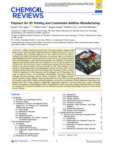
A 3D XML-Based Customized Framework for Dynamic Models Taewoo Kim
Paul A. Fishwick
University of Florida Computer and Information Science and Engineering Department University of Florida, Gainesville, FL 32611
University of Florida Computer and Information Science and Engineering Department University of Florida, Gainesville, FL 32611
[email protected]
[email protected]
ABSTRACT There are numerous forms for dynamic models, which specify how an object or scene behaves over time. Discrete state automata, Petri nets, and data flow graphs are only a few samples of model types available, which aid modelers in capturing dynamics. Whereas most modeling frameworks employ rigidly defined textual or 2D symbols for representing such abstract entities as state, event, and function, we present a system called rube that allows the modeler to craft models in 3D, and with personalized metaphors. The advantages of this system lie in the education of modeling dynamic systems, and in the exploitation of customization in the user interface. We use extensible 3D (X3D), and XML technology, to demonstrate rube, along with an example.
Categories and Subject Descriptors I.6.5 [Simulation and Modeling]: Model Development; K.3.1 [Computers and Education]: Computer Uses in Education
General Terms Aesthetic Computing, Model Design, Personalization
Keywords rube, XML, VRML, X3D, MXL, XSLT, 3D, dynamic modeling, personalization, aesthetic programming
1. INTRODUCTION As technology advances, the sheer magnitude of data and information that must be catalogued, sorted, presented, and fused grows rapidly. Especially within the context of a specialized area, such as Battle Infosphere [1,2], a key problem is fusion, not only of data but also of model information. The infosphere is often presented as a vast, cross-connected mass of information emanating from sensors, weapons, and military units. The task of integrating such mass of information effectively remains a key research problem in many areas. Our task is to leverage Extensible Markup Language (XML) technology to help solve the model fusion problem, where models of different sorts must be interconnected.
Three types of models, information, dynamic and geometric, are common in most applications. We have designed the existing rube research framework to fuse geometry and dynamic model information. In late 1998, at the University of Florida, Fishwick [3] and his research team developed a 3D modeling paradigm called rube, where the key task was to derive a methodology for constructing various dynamic models in a structured way, and to build a set of Virtual Reality Modeling Language (VRML) prototypes [4,5] to make it easy for modelers to choose common dynamic model types in their multimodels. Recently, we made a transition from VRML to X3D (eXtensible 3D). X3D is structured completely in XML, which is the language of the web being promoted by the Web3D Consortium [6]. Since XML has many benefits for model design, transitioning from VRML to X3D was natural and logical. The Extensible Stylesheet Language (XSL) [7], which is being developed as a part of the W3C Style Sheets Activity [8], enables us to transform documents written in XML. The XSL Transformations (XSLT) [9,10,11] is designed for use as a part of XSL to describe how one document is transformed into another XML document. We propose a 3D XML-based software architecture, including a demonstrable graphical user interface and the Model Fusion Engine, which supports the fusing of two common types of information: geometry models and dynamic models. This architecture provides an effective means to represent both geometry and dynamic information using XML and to encode the fusion process into the mediator. A Finite State Machine (FSM) is used in this article as an example model to describe the two representations and demonstrate the feasibility of creating a dynamic model from these files. An FSM, with three states and three transitions, is used to model the behavior of the real world light bulb with a pull chain. The overall XML-based rube architecture along with its subcomponents is addressed in section 2. A 3D dynamic model example using the architecture is presented in sections 3. Conclusions and future work are discussed in section 4.
2. XML-BASED rube ARCHITECTURE Overall structure of the XML-based rube architecture and each sub-component are discussed with an example in the following sub-sections.
2.1 Overall structure The overall structure of the XML-based rube architecture is shown in Figure 1 along with pointers to the sections covering that part. It includes a scene file, a model file, the Model Fusion Engine, and a graphical user interface (GUI) as sub-components. One of the major features of this modeling architecture, which distinguishes it from other 3D modeling architectures, is that it separates geometry from the inter-object semantic relations. Any scene file, which represents geometry and appearance, can be used along with a model file, which contains information about relations and behaviors of the model. Since there is no working X3D browser, a translator between VRML and X3D has been incorporated. This component will be removed as soon as a working version of an X3D browser appears. Another important feature is the existence of the Model Fusion Engine, which supports the merging and restructuring of XMLbased input documents representing the scene and the model as described above. The Model Fusion Engine handles the fusion process, where an important part of the fusion process is the integration of behavior, which is represented as blending scripts into the node structure of an XML document. The output of the fusion process is an integrated X3D file, which contains geometry scene information as well as the corresponding models and their behavior.
created with HTML, Perl and CGI scripts in order to automate the process of merging the two files: the scene file, which contains user-defined 3D geometry, and the model file, which is the topology file defining the connectivity and behavior of the model type. A model author specifies scene and model file using the GUI, which translate the two files and activate the Model Fusion Engine to create a 3D dynamic model.
2.2 Scene Files Scene files are obtained from the web from 3D “model repositories” or are created from scratch using a 3D modeler such as Cosmo Worlds or 3D Studio MAX. The first scene file, a light bulb, is shown in Figure 2. The light bulb is connected to a plug that supplies power, and a chain that turns the light on and off.
Figure 2. A light bulb The second scene file is shown in Figure 3. Even though somewhat more minimal in structure, this is meant to be a fluid processing plant with red tanks and green pipes.
Figure 3. A processing plant
Figure 1. XML-based rube architecture The Model Fusion Engine is an XSLT-based fusion mediator. XSLT is XML-based, meaning the XSLT processor is capable of analyzing an XML document and converting it into a node tree which can be efficiently manipulated and restructured using XSLT stylesheet. It accepts both scene and model files, analyzes each file and creates a new X3D file by merging and inserting scripts according to the relation and behavior specified in the model file. Currently, a Finite State Machine (FSM) is incorporated into the Model Fusion Engine. Other model types, such as Functional Block Model (FBM) and Petri Net (P-Net) [15], are being developed. Until a complete X3D browser becomes available, all the VRML files need to be translated into X3D files for the Model Fusion Engine. Also, the merged X3D file needs to be translated back into a VRML file to be displayed in the VRML browser. The graphical user interface (GUI) is
The modeling operation is one where one object is said to capture the essence of another. For our purposes, we use the processing plant to model the dynamics of the light bulb. We achieve this mapping by stating that the plant plays the role of an FSM with three states and three transitions. A 2D diagram of the FSM is depicted in Figure 4. off unplugged apply power pull chain on plugged
off plugged pull chain
Figure 4. 2D-FSM
A scene file contains nodes, which describe objects and their properties. It contains hierarchically grouped geometry that represents the 3D structure of a model to be constructed. The source code of a VRML scene file, scene.wrl (capturing the role playing semantics of Figure 3), is shown in Figure 5. #VRML V2.0 utf8 DEF S1 Transform { translation 0 3 -6 children Shape { appearance Appearance { material Material { diffuseColor 1 0 0 } } geometry Sphere {} } } DEF S2 Transform { translation 3 -2 -6 children Shape { appearance Appearance { material Material { diffuseColor 1 0 0 } } geometry Sphere {} } } DEF S3 Transform { translation -3 -2 -6 children Shape { appearance Appearance { material Material { diffuseColor 1 0 0 } } geometry Sphere {} } } DEF T12 Transform { children [ Transform { translation 1.35932 1.08298 -6 rotation 0 0 1 0.523201 children Shape { appearance Appearance { material Material { diffuseColor 0 1 0 } } geometry Cylinder { radius 0.25 height 1 } } } Transform { translation 1.85898 0.216755 -6 rotation 0 0 1 3.6632 children Shape { appearance Appearance { material Material { diffuseColor 0 1 0 } } geometry Cone { bottomRadius 0.45 height 1 } } } ] } DEF T23 Transform { children [ Transform { translation 0.5 -2.7499 -6 rotation 0 0 1 1.571 children Shape { appearance Appearance { material Material { diffuseColor 0 1 0 } } geometry Cylinder { radius 0.25 height 1 } } } Transform { translation -0.5 -2.7501 -6 rotation 0 0 1 1.571 children Shape { appearance Appearance { material Material { diffuseColor 0 1 0 } } geometry Cone { bottomRadius 0.45 height 1 } } } ] } DEF T32 Transform { children [ Transform { translation 0.499694 -1.2499 -6 rotation 0 0 1 4.711 children Shape { appearance Appearance { material Material { diffuseColor 0 1 0 } } geometry Cone { bottomRadius 0.45 height 1 } } } Transform { translation -0.500305 -1.2501 -6 rotation 0 0 1 1.571 children Shape { appearance Appearance { material Material { diffuseColor 0 1 0 } } geometry Cylinder { radius 0.25 height 1 } } } ] }
Figure 5. scene.wrl The model author can create new objects with a 3D modeling program, such as 3D Studio Max, or reuse any 3D objects found on the web and use it as a scene file. Since the Model Fusion Engine works on XML files, the model author should export the scene into a VRML file. The VRML scene file is automatically translated into an X3D file using the NIST translator during the model generating process. A translated scene file is fed into the Model Fusion Engine as an input along with a model file. A model file, which represents topology and relations as shown in Figure 5, is also fed into the Engine. In order for the Engine to merge the two files and generate a 3D dynamic model, each object in the scene file must be given a unique name, such as S1, S2, and T12, that will correspond to the id attribute value of each element in the model file. Naming is important when merging two different files, which describe the same model in two different ways. The Model Fusion Engine will copy each node in the scene file according to the same names specified in the model file. This architecture allows a model author to either create new 3D objects or reuse existing digital objects from "model warehouses", as well as from dynamic model repositories on the web. Instead of generating objects automatically by the Model Fusion Engine, much of the freedom in defining and creating 3D objects has been given to the model author. Objects can be personalized and made culturally or aesthetically meaningful [5,15] as shown in Figure 61 [13] and Figure 6-2 [14]. Both figures represent different metaphorical styles impressed upon the same scene file used in Figure 3.
Figure 6-1. fluid pipe metaphor
Figure 6-2. architecture metaphor
2.3 Model File A model file is written in Multimodel Exchange Language (MXL), which defines the topology and behavior of the model type. The model file is composed of two sub-components: model and simulation element as shown in Figure 7. model contains topology and behavior as sub-elements. topology defines the connectivity of the model and behavior describes the type of animation that signifies the current state. Currently, a graph grammar is used to represent the topology of the model, composed of node and edge elements. Each node and edge element has an attribute, id, to specify the names of states and transitions in an FSM. One of the nodes contains information, which labels the starting state. The edge element also has begin and end attributes denoting the start and the end state of each transition. The model author can assign unique names to each node and edge, but it is important that the names given here, such as S1 and S2, are identical to the names assigned to each object in the scene file. The Model Fusion Engine uses these names to link each component and blends necessary script into each node.
Figure 7. Model file in MXL
behavior, which is another sub-element of the model element, contains type of animation that will be executed in order to represent the current state in the 3D FSM model. Each behavior is defined as a separate module, and blended into the dynamic model by the Model Fusion Engine according to the specified behavior type. Currently, pulsate and vibrate behaviors are defined and implemented with the vibrate behavior further sub-divided into X, Y and Z-axis. With pulsate behavior, an object, which represents the current state, pulsates over time. Also, with vibrate behavior, an object vibrates along the axis, which the user specified in the model file. simulation, along with the model element described above, comprises the whole MXL file. It contains information about simulating the real world system being modeled with input data provided by either random generator or separate input data file stored locally. simulation element has type attribute, which denotes the type of dynamic model being simulated and three subelements: program, simTime and inputData element. program specifies the name of the main program, which runs the modules, such as queuing.js, in SimPack [15], developed in simulation lab at the University of Florida, to simulate the model. SimPack is a collection of tools for computer simulation, originally developed in C and C++. Currently, it is converted into JavaScript and being implemented within the XML-based rube architecture. The purpose of SimPack is to provide users with a discrete event simulation library. simTime has an attribute, duration, which represents the elapsed time between start time and end time of the simulation in milliseconds. inputData specifies the type of input data, which will be used in simulating the system. It can either be generated by the random generator or provided within a file containing input data. The model file written in MXL captures all the information about the model, topology that defines the connectivity of the model type and their behavior, as well as information needed to run the simulation. It provides an effective way to represent both geometry and dynamic model information using XML.
2.4 Model Fusion Engine
Figure 8. A fusion segment of ModelEngine.xsl file With the following two lines, each node element in the model.xml file is accessed and processed by the Model Fusion Engine:
A Transform element and a children element, which will contain geometry and script, are added in the fsm.xml file as follows:
These elements are inserted by the following lines:
With the following two elements, the value of id attribute, e.g., "S1", "S2", etc., is stored in the curr_state variable and the geometry node in the scene.xml file, which has the same name value in the attribute DEF, is copied to the fsm.xml file:
Each selected Transform element is copied from the scene.xml file to fsm.xml file as follows:
The Model Fusion Engine plays central role in the 3D dynamic modeling process within rube. There are two processes in the Model Engine: the fusion and the blending processes. In the fusion process, two XML documents are fused into another XML document. In the blending process, behavior is blended into node structures of a newly created XML document as a script node.
The fusion process of the Engine is an XSLT-based process, where the two XML documents, scene.xml and model.xml, are used as input and an XML file, called fsm.xml, is produced as a final output. It first examines the model file, which contains topology and behavior of a system being modeled, and constructs a 3D dynamic model according to the specifications shown in Figure 7. The skeleton of the dynamic model is created by copying all the geometries from the scene file that matches the names of each corresponding node and edge in the model file. A segment of code, which copies all the nodes, is shown in Figure 8.
The blending process adds JavaScripts and ROUTE statements to the static skeleton of the 3D model and makes it a dynamic model, which performs a desired behavior. According to the behavior specified in the model file, corresponding script is appended to each object in the fsm.xml file. The control script is also created to synchronize the behaviors of each object. The ROUTE statements, which serve as the nerve system in which the control signals could flow, are also attached to the final 3D dynamic model. A segment of code, which blends script and ROUTE elements to the fsm.xml file, is shown in Figure 9.
javascript: function currState(value) { name = value; }
Figure 9. A blending segment of ModelEngine.xsl file
JavaScript version of the SimPack [17] written in C and C++. By providing modeling and simulation capabilities, the Model Fusion Engine supports the rube to comprehend both processes.
2.5 GUI A simple user interface is provided on the web [18] as shown in Figure 10. There are two sections in the window: the lower part of the screen where a user can specify or upload user-defined scene and model files and the upper part of the window where newly created 3D dynamic model is displayed with a VRML browser such as Blaxxun Contact, Parallel Graphics' Cortona, or Cosmo Player.
With the code denoted in the Figure 9, a Script element, which contains javascript functions, is added to the Transform element with the same id value, e.g., "S1", in the fsm.xml file as follows:
This section displays newly created 3D dynamic model with a VRML browser.
This section accepts user defined scene and model files.
Since the value of type attribute of behavior element in the model.xml file is "VIBRATE", the name of the Script element is defined as "STATE_S1_VIBRATE" and it is used in the ROUTE element to pass an event as follows:
Figure 10. Graphical User Interface
When a user specifies scene and model files, the scene file, which is a VRML world either created or exported from other 3D software such as CosmoWorlds or 3D Studio Max, is translated into an X3D file using the NIST translator [19] and fed into to the Model Fusion Engine. The model file, which is a user-defined XML file containing topology and dynamic behavior of the model, is also fed into the Model Fusion Engine as an input. The Model Fusion Engine in the background merges two files and creates an X3D file, which represents the 3D dynamic model with the specified behavior. The final result is then translated into a VRML file and displayed in a VRML browser as shown above.
For each id, following ROUTE element is added to fsm.xml file:
Other functions and control Script element are also added to the fsm.xml file to produce a dynamic 3D FSM model in XML. The Model Fusion Engine is developed with XML Spy version 4.0 from Altova [16], an Integrated Development Environment (IDE) for XML. It supports XML document editing and validation, W3C's XSD Recommendation, and XSLT. The XSD, XML Schema Definition language, is an XML-based grammar for describing the structure of XML document, such as the model file being used in our modeling process. XML Spy can validate the XML document against an XSD schema, such as MXL, Multimodel Exchange Language, created for the modeling process in the rube architecture. In order to support the simulation process of a model, the simulation capability, which is empowered by SimpackJS, is being added to the Model Fusion Engine. The SimpackJS is the
3. 3D DYNAMIC MODEL EXAMPLE In this section, we present an extended working example of 3D dynamic model created with the Model Fusion Engine. With the previous VRML prototypes, a modeler had to hand code all the components in 3D world to create a dynamic model. This modeling process can be expedited with the use of Model Fusion Engine. A modeler can use any shape of geometry and define any number of geometries with inter-relations between each element in the model file. First, the scene file, saved as "scene.wrl", used in this example is shown in Figure 11. This file is created with Cosmo Worlds and saved as a VRML file. It contains only the geometries that will be used to represent each state and transition in the FSM model. For the demonstration purposes, all the possible transitions from one state to the other state have been created in a file except the ones that loops itself.
Figure 14. variations
Figure 11. VRML scene.wrl A model file, saved as "model.xml", used to specify topology of the model, e.g., the information about each node and edge, is shown in Figure 12.
select whi
Figure 12. model.mxl By modifying the number of node and edge elements in the model file, a modeler can ch objects to include in the final FSM world to represent each state and transition. By defining suitable transition information, behaviors that represent the actual state changes are encoded by the Model Fusion Engine and visualized in the final FSM model. The resulting FSM world created from the model.xml file is shown in Figure 13.
Objects can be personalized and made aesthetically meaningful to the modeler. The Model Fusion Engine was provided to the simulation class at the University of Florida for students to create their own dynamic models using the rube architecture. Examples of an FSM model and an FBM model created by the students are shown in Figure 15 and 16.
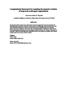
Figure 15. Elevator FSM example The FSM example shown in Figure 15 was created by Noa et. al. [20]. Five groups of objects, including the MCP (Master Control Program), the I/O tower, and two towers from "Tron", represent each state of an elevator. Each object has its own animation to represent the current state. A transition from one state to another state is represented by a moving solar sailor.
Figure 16. 3D Plotter FBM example
Figure 13. Resulting FSM Some of the resulting FSM models with different variations described above are shown in Figure 14. In these examples, state changes are represented by pulsating the current state. Different behaviors, such as 'VIBRATE', can be defined in the model file.
The FBM example shown in Figure 16 was created by Park et. al. [21]. It models and simulates a mathematical equation, the spiral of Cornu, using a functional block model. As time changes, x and y values are generated by integrating the cosine and sine values. These generated x and y values are fed into the next block, the 3D Virtual Plotter, where the actual 3D graph is drawn by the moving arm. Also, generated x and y values are drawn on the black board. Other examples and more detailed information of each model can be found at the URL [22].
4. CONCLUSIONS AND FUTURE WORK Our goal is to create a software environment that allows the user to customize or personalize content for dynamic model structure such as finite state machines, and data flow graphs. We have built an architecture called rube to achieve that goal. The MXL interchange language allows us to specify content independent of presentation, so that XML stylesheets can be used to present the MXL model in a way that is satisfactory to the author, or the end user. To date, we have only achieved some of our goals for rube, since we have defined the finite state machine model in MXL but no others. We also need to create a core set of alternate model types, and allow these model types to be defined in a hierarchy of heterogeneous models---a multimodel. We have started on the construction of another XML language, called DXL (Dynamics eXchange Language) to facilitate model specification in MXL. DXL represents a low, assembly level, modeling exchange language whose components are uniform as in a digital circuit. For the moment, MXL operates independently of DXL, but will in the near future depend upon it for its lower level operation. The issue of scalability is also of concern to us. How scalable is this approach, and can rube help with solving scale problems?
5. ACKNOWLEDGMENTS Our work on aesthetic computing and rube and is supported by the National Science Foundation under grant EIA-0119532 and the Air Force Research Laboratory under grant F30602-01-10592. We would also like to thank Minho Park, Andrea Goethals, and Jinho Lee for their work on the graphical user interface and SimPackJS.
[5] Kim, T. and Fishwick, P. A. Virtual Reality Modeling Language Templates for Dynamic Model Construction. Enabling Technology for Simulation Science within SPIE '01 AeroSense Conference, Orlando, April 2001.
[6] X3D Graphics Working Group, http://www.web3d.org/x3d.html
[7] Extensible Stylesheet Language, http://www.w3.org/Style/XSL/
[8] W3C Style Sheets Activity, http://www.w3.org/Style/Activity/ [9] XSL Transformations, http://www.w3.org/TR/xslt/ [10] Michael Kay. XSLT Programmer's Reference, Wrox Press, 2000.
[11] Steven Holzner. Inside XSLT, New Riders, July 2001. [12] P. A. Fishwick. Simulation Model Design and Execution: Building Digital Worlds, Englewood Cliffs, NJ: PrenticeHall, 1995.
[13] Donahue, Ryan. http://www.cise.ufl.edu/~fishwick/rube/tutorial/Fsm4/world4 .wrl
[14] Kohareswaran, Naganandhini. http://www.cise.ufl.edu/~fishwick/rube/tutorial/Fsm5/world5 .wrl
[15] Fishwick, P. A. Aesthetic Programming, Leonardo, MIT Press (to be published in 2002).
[16] XML Spy, http://www.xmlspy.com/ [17] P. A. Fishwick, Simpack: Getting Started with Simulation
6. REFERENCES [1] Mark H. Linderman. The joint battlespace infosphere. AFRL Horizons, June 2001.
[2] Mark Pronobis. Battlespace awareness through information fusion. AFRL Horizons, June 2001.
[3] Fishwick, P. A. On Web-Based Models and Repositories,
Programming in C and C++, In 1992 Winter Simulation Conference, pages 154-162, Arlington, VA, December 1992.
[18] Fishwick, P. A. rube web page, http://www.cise.ufl.edu/~fishwick/rube/
[19] NIST translator between VRML97 file and X3d file, http://www.itl.nist.gov/iaui/ovrt/v2_x3d.html
Enabling Technology forSimulation Science within SPIE '01 AeroSense Conference, Orlando, April 2001.
[20] http://www.cise.ufl.edu/class/cap4800fa01/Project/Pro2/Tea
[4] Hopkins, J. and Fishwick, P. A. The rube Methodology for 3-
[21] http://www.cise.ufl.edu/class/cap4800fa01/Project/Team_4.
D Software Engineering, Springer Verlag Computer Science Series on Software Visualization, August 2001.
m_1.wrl wrl
[22] http://www.cise.ufl.edu/class/cap4800fa01/