IEEE TRANSACTIONS ON VERY LARGE SCALE INTEGRATION (VLSI) SYSTEMS, VOL. 13, NO. 2, FEBRUARY 2005
201
A “Flying-Adder” Frequency Synthesis Architecture of Reducing VCO Stages Liming Xiu, Senior Member, IEEE, and Zhihong You, Member, IEEE
Abstract—The “Flying-Adder” architecture is a frequency and phase synthesis technique that is based on a voltage-controlled oscillator (VCO) of multiple delay stages. Since the invention of this architecture, various improvements have been made during many implementations of this technique. One of the remaining issues is to reduce the number of delay stages inside the VCO for the benefit of low power consumption and easy design/layout implementation. This paper presents a modified version of the architecture, by utilizing the scalability presented by Xiu and You, 2002, to achieve this goal. The modified architecture can also be used to improve the number of synthesizable frequencies. The tradeoff for this architecture of reduced-delay-stage VCO is the circuit speed. Index Terms—Flying-adder, frequency synthesis, phase-locked loop (PLL), voltage-controlled oscillator (VCO).
I. INTRODUCTION
T
HE “Flying-Adder” frequency and phase synthesis architecture was invented several years ago [1]. Since then, the original architecture has been improved in various areas: 1) the circuitry’s speed performance has been improved significantly [2]; 2) scalability has been introduced into the architecture for expansion [2]; and 3) a new method has been proposed for improving its jitter performance [3]. Those advances have made this architecture more mature and reliable. However, during the various implementations of this architecture, it was found that the architecture could be further improved if the number of voltage-controlled oscillator (VCO) delay stages could be reduced. The design/layout mismatch of the multiple delay stages of the VCO is the most significant noise source. For a fewer-stages VCO, the severity of mismatch is reduced and so is the noise. Furthermore, the power consumption can be reduced due to the fewer number of stages, which are the major current sinks in the system. In current practices, the number of stages used is either 31 [1] or 32 [2], [3]. Achieving perfect match on these many stages is not an easy task, especially in layout. As shown in the Appendix, frequency error is directly related to the delay stages’ mismatch. But simply trimming the number of stages will reduce the number of available phases for synthesis and, hence, would have negative impact on performance. This paper introduces a new technique to reduce the VCO delay stages but keep the number of available phases intact. In this mechanism, the time resolution of the VCO is preserved by increasing the VCO frequency correspondingly (to compensate the effect of
Manuscript received August 4, 2003; revised September 21, 2004. The authors are with Texas Instruments Inc., Plano, TX 75024 USA (e-mail:
[email protected]). Digital Object Identifier 10.1109/TVLSI.2004.840776
Fig. 1. The principle idea of the Flying-Adder.
fewer stages). The overall synthesizer performance is restored by the utilization of the parallel paths (“scalability” introduced in [2]). This paper can also be viewed as investigating the scalability of the Flying-Adder from another angle that is not presented or obvious in [2]. In this paper, Section II gives a brief history of the FlyingAdder architecture. Section III discusses the concept of available phases. Section IV discusses how to utilize this concept to reduce the number of VCO stages. This concept can also be implemented as a technique to improve the number of synthesizable frequencies, and this is addressed in Section V. The Appendix is the study of frequency error due to the delay-stages’s mismatch. II. THE EVLOUTION OF THE FLYING-ADDER A. The Original Flying-Adder Fig. 1 gives the principle idea of Flying-Adder architecture. This architecture utilizes the multiple phase outputs from a multiple-delay-stages VCO to synthesis various frequencies. In this architecture, the accumulator-register has some bits reserved for fractional parts to achieve certain frequencies. In the 10-bit accumulator-register of Fig. 1, 5 bits are for integer, and 5 bits for fraction. For example, if we have a VCO of 32 outputs
1063-8210/$20.00 © 2005 IEEE
Authorized licensed use limited to: TEXAS INSTRUMENTS VIRTUAL LIBRARY. Downloaded on April 9, 2009 at 23:04 from IEEE Xplore. Restrictions apply.
202
Fig. 2.
IEEE TRANSACTIONS ON VERY LARGE SCALE INTEGRATION (VLSI) SYSTEMS, VOL. 13, NO. 2, FEBRUARY 2005
The numerical illustration.
that are running at 156.25 MHz (6.4 ns), then the time difference ns between two adjacent VCO outputs is ns. If the desired frequency of output signal Z is 204.08 MHz (4.9 ns), then the FREQ [9:0] can be calculated as FREQ [9:0] ns ns, or FREQ [9:0] b. Fig. 2 illustrates how this is achieved. When the fractional part of frequency control word FREQ is nonzero, the resulting frequency is in the fashion of “timeaverage frequency”. The frequency resolution is related to both the frequency and the number of fractional bits, as shown in [3, eq. 7]. B. The Flying-Adder With Scalability In the circuit level, the Flying-Adder architecture has been improved in two areas in [2]: 1) the circuitry is optimized and its working speed is increased significantly and 2) scalability has been introduced to the architecture. This scalability enables multiple paths to be utilized for generating higher output frequency; it is also the foundation of this paper. Fig. 3 [2, Fig. 7] is the two-path circuitry with scalability.
Fig. 3. (Fig. 7 of [2].) The two-path Flying-Adder synthesizer with scalability.
C. Integer-Flying-Adder For certain frequencies, the Flying-Adder architecture uses the periodical carry-in of the accumulator-register for compensation. The resulting time-average frequency contains inherent jitter in those cases. For applications of tight jitter requirement, this is not acceptable. The “Integer-Flying-Adder” presented in [3] eliminates the need of the fractional part in frequency control word FREQ and the associated inherent jitter is nonexistent in this method. The tradeoff is the increasing complexity of the phase-locked loop (PLL). III. THE NUMBER OF AVAILABLE PHASES The Flying-Adder architecture is based on a VCO of outputs. These outputs, or ticks, will be used repetitively every time the accumulator rolls over. The number of outputs has direct impact on the synthesizable frequency points that are available from this architecture. It is obvious that the larger is, the more frequency points there will be. Fig. 4 shows the signal Z of a certain frequency. Z DIV2 and Z DIV4 are the divided-down versions of this signal. If the one-path circuitry of Fig. 1 is used, then edges A, B, and C of a full cycle of Z all have to be generated by this path. The maximum number of ticks available for when both the falling edge a full cycle (from A to C) is B and rising edge C require the maximum number of ticks without the accumulator rolling over. For the two-path circuitry
Fig. 4. The waveforms and ticks.
of Fig. 3, the maximum number of available ticks is also , but the rising and falling edges are generated by different paths. For a four-path version, as shown in Fig. 5 [2, Fig. 12], the maxfor signal Z since any signal imum number of ticks is still has only two edges in one cycle, but edges A, B, C, and D of two cycles are all generated from different paths. The advantage of using multiple paths is to relax the constraint on the speed of the accumulator [2]; it does not necessarily increase the number of available ticks for signal Z. However, instead of Z, if one studies the signal of Z DIV2, it , is clear that the maximum available ticks for this signal are and for Z DIV4 it is . For these signals, we virtually increase the number of available ticks by utilizing multiple paths. In other words, by using multiple parallel paths and at the expense of circuit speed (as will be shown later), we “create” more VCO outputs without physically modifying the VCO structure.
Authorized licensed use limited to: TEXAS INSTRUMENTS VIRTUAL LIBRARY. Downloaded on April 9, 2009 at 23:04 from IEEE Xplore. Restrictions apply.
XIU AND YOU: “FLYING-ADDER” FREQUENCY SYNTHESIS ARCHITECTURE OF REDUCING VCO STAGES
203
Fig. 5. (Fig. 12 of [2].) The four-path Flying-Adder synthesizer.
IV. REDUCE THE NUMBER OF VCO DELAY STAGES A. The Idea In Fig. 5, a four-path circuitry is demonstrated, where . Thus, the available ticks for signal Z is . If we make (double the VCO frequency) and, instead of using signal Z, make use of signal Z DIV2, then the available ticks for Z DIV2 are still . By the same token, we can reduce further to 8 and achieve the same available ticks by utilizing an eight-path circuitry. The implementation of these two cases will be discussed in Section IV-C and D. B. Analysis In this section, before proceeding to the implementation, we will study the issues of synthesizable frequencies and frequency range of a 64-tick system for three cases: two-path four-path , and eight-path . The frequency control word for all three cases is 6-bit FREQ [5:0]. Also, a reference frequency is defined as . 1) For Signal Z of two-path : The highest synthesizable frequency FREQ is achieved when FREQ [5:0] , or . The lowest frequency is FREQ [5:0] , or . The available frequency points for Z are if no fractional part is used. These 63 frequencies are distributed in fashion as shown in plot 1 of Fig. 6. 2) For Signal Z DIV2 of four-path : Since four paths are used and each path has to be activated once for a full cycle of Z DIV2, the highest frequency is obtained when FREQ [5:0] . Thus, we have
Fig. 6. The frequency points for different
N.
. The lowest frequency is reached when FREQ [5:0] (each path uses its maximum ticks), thus . But the available frequency points for Z DIV2 are . These 61 frequencies are shown in plot 2 of Fig. 6. 3) For Signal Z DIV4 of eight-path : By the same token, and . The available frequency points are . These are shown in plot 3 of Fig. 6. Plot 4 is the overlap plot of the previous three plots. For the Flying-Adder architecture, the output signal’s frequency is inversely proportional to the magnitude of FREQ . This is clearly shown in Fig. 6. Also shown in the above analysis
Authorized licensed use limited to: TEXAS INSTRUMENTS VIRTUAL LIBRARY. Downloaded on April 9, 2009 at 23:04 from IEEE Xplore. Restrictions apply.
204
IEEE TRANSACTIONS ON VERY LARGE SCALE INTEGRATION (VLSI) SYSTEMS, VOL. 13, NO. 2, FEBRUARY 2005
Fig. 7. Four-path with sixteen VCO outputs.
is that the four-path circuitry loses two frequencies in the highfrequency end; the eight-path version is six frequency points less than that of the two-path. The frequency distributions for the three cases are exactly the same as shown in plot 4 since FREQ applies to all the cases. C. Implementation of Four-Path With Sixteen VCO Outputs Fig. 5 is the implementation of four-path architecture with 32 VCO outputs. The goal of that circuitry is to increase the frequency of the output signal Z. Fig. 7 is the modified version of that circuitry with VCO outputs and an extra divider after Z. In this design, what we intend to achieve is the equivalent result, in term of available frequency points, of two-path circuitry of . 1) The Circuitry: In Fig. 7 there are 16 VCO outputs, Tick[15:0], which are locked to a reference through a PLL. All the MUXs, except MUX5, are . MUX5 is . All the registers and adders, except the accumulator, are 4 bits wide. Accumulator Adder1 and its associated register REG11 can be wider than 4 bits if fractional part is used. The block CLK CNTL will generate the clock control signals and Gray-coded SEL5 (as shown in Fig. 13 of [2]). The Z DIV2 is the final output signal with the desired frequency. 2) The Duty Cycle: In Fig. 4 a full cycle of Z DIV2 is from edge AA to edge EE that consists of four edges of B, C, D, and E of signal Z. Each of the four paths in Fig. 7 is responsible for one of the edges. Therefore, the duty cycle of Z DIV2 is related to the inputs of the adders X1, X2, X3, and X4. Judicious arrangement of these values will ensure that the maximum dutycycle misalignment % is , as shown below. The input to Adder1 is always the 4 LSBs of FREQ [5:0] (X1 FREQ [3:0]) since it is the accumulator, the base for the other three adders to start from. For X2, X3, and X4, we need to
consider the following four cases of FREQ [5:0]: (1) ; (2) ; (3) ; (4) . For case (1), FREQ [5:0] is dividable by 4. Thus, the four segments (A-B, B-C, C-D, D-E) of a full cycle of Z DIV2 (from edge AA to edge EE) can have the same length of FREQ FREQ [5:2]. In this case, the duty cycle of Z DIV2 is 50%. So the X2, X3, and X4 can be set as
FREQ FREQ FREQ In above equations, FREQ FREQ [4:1] and FREQ [5:2]. For case (2), FREQ [5:0] is not dividable by 2. In this scenario, we want segment AA–CC one longer than segment CC–EE, or segment A–B one longer than the rest of three segments. So we have
FREQ
FREQ FREQ FREQ FREQ FREQ For case (3), FREQ [5:0] is dividable by 2, but not by 4. We want segment A–B and C–D one longer than B–C and D–E, so the duty cycle is 50% and
FREQ FREQ FREQ FREQ FREQ
Authorized licensed use limited to: TEXAS INSTRUMENTS VIRTUAL LIBRARY. Downloaded on April 9, 2009 at 23:04 from IEEE Xplore. Restrictions apply.
XIU AND YOU: “FLYING-ADDER” FREQUENCY SYNTHESIS ARCHITECTURE OF REDUCING VCO STAGES
Fig. 8.
205
SPICE result of four-path and FREQ = 20.
Finally, for case (4), we want segment D–E one than the other three:
shorter
FREQ FREQ FREQ FREQ FREQ FREQ FREQ The formulas for the four cases can be generalized as
FREQ FREQ FREQ FREQ FREQ FREQ FREQ Note that X1, X2, X3, and X4 are static values when
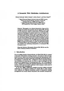
FREQ [5:0] is determined. Unlike the MUXs’ address values SEL1-5, they do not need to be updated from cycle to cycle in real time. 3) The SPICE Result: The circuitry of Fig. 7 has been implemented in a 0.13- m 1.5-V digital CMOS process, which is the same process used for the circuitries in [2]. Fig. 8 is the SPICE simulation result of FREQ [5:0] . Since the VCO is running at 573.39 MHz and has 16 outputs, we have ns. The calculated frequency for this case is MHz (2.18 ns). The SPICE simulation shows measured frequency of 458.7 MHz. The first signal from the top, VCLK OUT, is the waveform of Z DIV2. The second one, VCLK OUT INT, is the waveform of Z. The third one is TRIGGER. The next two, VSEL5 0 and VSEL5 1, are the address signals of MUX5. VCLK1–4 are the clock control signals. It can be seen that every rising edge of TRIGGER will cause a signal transition on VCLK OUT INT and every rising edge of that signal will cause VCLK OUT makes a transition. So TRIGGER is working at the speed of four times that of
VCLK OUT. The MUX5’s address signals are indeed in Garycode fashion. They are also correlated with the clock control signals, VCLK1–4, as defined in Fig. 13 of [2]. Also demonstrated is that a full cycle of synthesized output VCLK OUT contains four rising edges of clock signals CLK1–4. Each of these clock signals triggers the corresponding path in sequence to build the final output waveform. D. Implementation of Eight-Path with Eight VCO Outputs If eight-path circuitry is used, the VCO outputs can be further reduced to 8 for equivalent 64 VCO ticks. Fig. 9 is the schematic of this eight-path system. 1) The Circuitry: There are eight paths in this circuitry. All the registers and adders, except Adder1 and REG11, are 3 bits wide. Adder1 is the accumulator whose size depends on the fractional part used; its integer part is also 3 bits wide. All the MUXs are with 3-bit address. Z DIV4 is the final output of desired frequency. CLK CNTL is a control block that generates the clock signals for registers in each path. It also delivers the address signals for MUX9. To ensure that MUX9 does not produce a glitch on its output, at most one bit among its three address bits is allowed to switch at any given time. Gary coding on SEL9 is used for this purpose: . To ensure that the glitches at the outputs of MUX1, MUX2, , MUX8, which are the eight inputs of MUX9, are not passed through MUX9, we need to do the MUX1 (or MUX2, , MUX8) address decoding when its output is not selected by MUX9. This can be achieved by doing the decoding one (or more) trigger(s) ahead. Fig. 10 is the required relationship among the clock signals and SEL9, which will guarantee the glitch-free feature on signal TRIGGER. 2) The Duty Cycle: As shown in Fig. 4, a full cycle of Z DIV4 is composed of eight segments of Z, A–B, B–C, ,
Authorized licensed use limited to: TEXAS INSTRUMENTS VIRTUAL LIBRARY. Downloaded on April 9, 2009 at 23:04 from IEEE Xplore. Restrictions apply.
206
IEEE TRANSACTIONS ON VERY LARGE SCALE INTEGRATION (VLSI) SYSTEMS, VOL. 13, NO. 2, FEBRUARY 2005
Fig. 9. Eight-path and eight VCO outputs.
(5) ; (6) ; (7) ; (8) . By using the same reasoning as with the four-path case, the following formulas will guarantee that the maximum duty-cycle misalignment of Z DIV4 is .
Fig. 10.
Clock and control signals.
H–I. Each of these segments is generated by one of the eight paths. The same as in the previous section, the length of each segment has impact on the duty cycle of Z DIV4 and those lengths are related to the inputs of the adders: . For this eigth-path circuitry, their values need to be evaluated under the following eight cases of FREQ [5:0]: (1) ; (2) ; (3) ; (4) ;
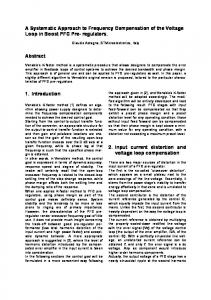
FREQ FREQ FREQ FREQ FREQ FREQ FREQ FREQ FREQ FREQ FREQ FREQ FREQ FREQ FREQ FREQ FREQ where FREQ FREQ [5:3] and FREQ FREQ [3:1]. 3) SPICE Result: Fig. 11 is the SPICE result of FREQ [5:0] . The calculated frequency is ns (169.89 MHz). The measured result from this SPICE run is 5.881 ns. The first signal, VCLK OUT, from the top is the waveform of output Z DIV4. The second one is TRIGGER. The third to fifth signals are the address value of MUX9. The other eight signals are the clock control signals. The SPICE waveforms of the MUX9 address and clock control signals match the requirement presented in Fig. 10. Other SPICE simulations
Authorized licensed use limited to: TEXAS INSTRUMENTS VIRTUAL LIBRARY. Downloaded on April 9, 2009 at 23:04 from IEEE Xplore. Restrictions apply.
XIU AND YOU: “FLYING-ADDER” FREQUENCY SYNTHESIS ARCHITECTURE OF REDUCING VCO STAGES
Fig. 11.
207
SPICE result of eight-path and FREQ = 54.
(not shown here) also show that the highest synthesizable frequency from this circuitry is 240 MHz, which is half of that of four-path and one-quarter of that of two-path. This is due to the fact that the internal circuit node that has the highest switching speed is TRIGGER and the speed up-limit of TRIGGER is applied to all three circuitries (two-path, four-path, eight-path) equally if they are implemented in the same process. In the case of eight-path, TRIGGER is switching at the speed of eight times that of VCLK OUT. As previously mentioned, the fastest working block in this architecture is CLK CNTL which operates at the speed of TRIGGER. By checking Figs. 9 and 10, it is clear that this block is a simple state machine that can be implemented easily in the digital domain. The particular technology process on which this architecture is implemented will determine the speed up-limit of CLK CNTL and, hence, the final highest output frequency. In this 0.13- m 1.5-V CMOS digital process, the CNTL CLK can be implemented as fast as 1.9 GHz. Therefore, the highest output from the two-path circuitry will be 1.9 GHz 950 MHz, 475 MHz for four-path, and 237 MHz for eight-path. E. Summary In the Flying-Adder architecture, the sole purpose of the VCO is to generate reference signals of certain known frequency. The VCO frequency itself is not the primary concern. The critical parameters are the delay stage’s delay and the number of stages . The resolution of the synthesized frequency solely depends on . The available frequency points are closely tied to . In general, more synthesizable frequency points require larger , which in turn increases the difficulty of hardware implementation. However, the concept of multiple paths can be
used to reduce the number of VCO stages without sacrificing the number of available frequency points. Compared to the traditional two-path Flying-Adder synthesizer, the frequency spectrum of the multiple-path synthesizer is shifted down toward the low-frequency end since it requires more time for the additional hardware elements to function. In other words, the tradeoff of this technique is that the output frequency from the multiplepath synthesizer is scaled down proportionally from the twopath one. It is also worthwhile to repeat that the highest achievable frequency from the Flying-Adder architecture in a particular technology process is not related to VCO frequency, but solely depends on the process speed.
V. IMPROVE THE NUMBER OF AVAILABLE FREQUENCY POINTS In Section IV, scalability has been utilized to reduce the VCO stages for lower power consumption and easy design/layout implementation. This feature can also be used to help increase the available frequency points if we investigate it from another point of view. In this section, we will study the frequency range and available frequency points for two-path, four-path, and eightpath circuitries when the number of VCO stages (and thus, VCO frequency) is fixed. A. Two-Path For two-path circuitry, there are two paths used to generate the output Z. The maximum available tick for each path is . , assuming Therefore, the available frequency points is that no fractional part is used. FREQ can take any value be. The reason the low limit is not 1, but 2, is due tween 2 and to the fact that one cycle of any signal has two edges and at least two ticks are needed for generating these two edges.
Authorized licensed use limited to: TEXAS INSTRUMENTS VIRTUAL LIBRARY. Downloaded on April 9, 2009 at 23:04 from IEEE Xplore. Restrictions apply.
208
IEEE TRANSACTIONS ON VERY LARGE SCALE INTEGRATION (VLSI) SYSTEMS, VOL. 13, NO. 2, FEBRUARY 2005
jitter in some cases. They are time-average frequencies for certain FREQ values. But the maximum cycle-to-cycle jitter is if the inputs of the adders are arranged in the way shown in previous sections. D. Comparison of Frequency Error Distribution
Fig. 12.
Frequency distributions of various circuitries.
If is the output frequency and the frequency range of two-path can be calculated as
, then
(1)
B. Four-Path Since four paths will be used and each path has maximum of ticks, the maximum number of ticks available for Z DIV2 . The highest frequency is achieved when four ticks are is used; each path of one tick is activated once for a full cycle of Z DIV2, which consists of four rising edges of TRIGGER. The . total available frequency points are
(2)
C. Eight-Path By the same token, FREQ can take any value between and . The available frequency points are . The frequency range is
In [3], the Integer-Flying-Adder architecture is constructed by eliminating the FREQ ’s fractional part and varying the PLL divide ratio for different frequencies. Unlike the original FlyingAdder, the available frequency points from the Integer-FlyingAdder are limited due to the elimination of the fraction part in the frequency control word. The available frequencies depend upon the PLL divider’s range and the available VCO ticks. If the technique presented in this paper is combined with the Integer-Flying-Adder, we can obtain more frequency points and, hence, better frequency error distribution. Fig. 13 is the frequency error comparison of two approaches. The top plot shows . The middle Fig. 3 of [3] with available VCO ticks of plot is the frequency error distribution envelope of eight-path . As mentioned in [3], the low with available ticks of limit of the top plot is 143 MHz. The middle plot’s low limit is 35.7 MHz since eight-path has a divide ratio of 4. The error distribution of eight-path is much better than that of two-path, which is clearer in the bottom plot. This plot is the zoom-in plot of the above two in the range of 150–170 MHz. The dashed line is for two-path; the solid line is for eight-path. VI. CONCLUSION This paper has investigated the scalability of Flying-Adder architecture from another angle. Originally, scalability (or multiple-path) has been used to improve the circuit speed and increase the achievable high frequency. In this paper, it has been utilized to virtually increase the number of available VCO ticks. This feature can be used for the purpose of reducing the number of VCO delay stages, or increasing the synthesizable frequency points. The tradeoff of utilizing this technique is the lower output frequency since one internal circuit node (TRIGGER) works at much higher speed than the output signal does. It can be useful in applications where lower power consumption and more available frequency points are required.
THE EFFECT OF MISMATCH (3) Fig. 12 shows the plots of frequency-point distributions for . Plot 4 of Fig. 12 is the the above three cases when overlap of the three previous plots. By examining (1) and (3), and also plot 1 and plot 3, it is obvious that the frequency range of two-path can be shifted down to the same range of eight-path by a divider of ratio 4, but the available frequency points of plot . Meanwhile, the frequency points are 1 are only for plot 3 of eight-path. In the eight-path circuitry of Fig. 9, the signals Z and Z DIV2 might be used as outputs if higher frequencies are needed. However, one needs to be careful when using these signals since they contain inherent
The Flying-Adder architecture uses the delay stages in the VCO to synthesize frequencies. Thus, the matching of the stages is very important. Any mismatch among these stages will result in frequency error and spurious signals on the output. Mathematically modeling these mismatches is not an easy task due to the fact that the “bad” stages can be located anywhere and the number of “bad” stages can vary greatly. In this Appendix, we will use a simple model of one “bad” stage to study the effect. Define as the ideal delay of each stage when all of them are matched perfectly. Also, assume that out of the stages, there “good” stages. The mismatch of is one “bad” stage and this “bad” stage will make its delay deviate from the ideal and . This mismatch will also make the delays of it can be called the “good” stages not equal to , and it will be called .
Authorized licensed use limited to: TEXAS INSTRUMENTS VIRTUAL LIBRARY. Downloaded on April 9, 2009 at 23:04 from IEEE Xplore. Restrictions apply.
XIU AND YOU: “FLYING-ADDER” FREQUENCY SYNTHESIS ARCHITECTURE OF REDUCING VCO STAGES
Fig. 13.
209
Comparison of frequency error.
Since the PLL is locked to a reference, the following is true:
If
FREQ
takes the value of , the ideal frequency should be . By the existence of this single mismatch stage, and , and this frequency will be split into two frequencies under the condition of since some cycles of the output will include the “bad” stage and some cycles will not . to deviate from by Assuming that the mismatch causes percent, then we have
Fig. 14.
The frequency errors of
and
can be calculated as
As shown in the above equations, the degrees of errors are proportional to the magnitude of the mismatch and the two is frequency, errors are in opposite directions. The error of or , independent (as shown in the left plot of Fig. 14). But the
Impact of one “bad” stage.
is frequency dependent that can be understood intuerror of itively. The possibility, which corresponds to power or energy, is . The possibility of is of . Fig. 14 is the error plot of and when mis% and . The right plot is the possibility match plot. The total energy of is split into two parts, and . The percentages of each part depend on the frequency, or . . If falls into the The above analysis is for , then range of , where , and similar development can be derived. If a model of multiple “bad” stages is used, then we can expect that the would be split . The mathematic treatment is similar but into
Authorized licensed use limited to: TEXAS INSTRUMENTS VIRTUAL LIBRARY. Downloaded on April 9, 2009 at 23:04 from IEEE Xplore. Restrictions apply.
210
IEEE TRANSACTIONS ON VERY LARGE SCALE INTEGRATION (VLSI) SYSTEMS, VOL. 13, NO. 2, FEBRUARY 2005
much more lengthy since we have to consider all the combinations. Note that in the above discussion we did not discuss the sit, or . The reason is that under uations when period is multiple(s) those conditions, the output signal’s of the VCO’s period and all the mismatches cancel each other, regardless of the number of “bad” stages, the locations, and the magnitudes. In other words, the mismatch of the delay stages or will not have any impact on the output when . The design/layout matching of the delay stages is very important for this architecture. There are some techniques that can be applied for good matching in layout.
Liming Xiu (M’95–SM’03) received the B.S. and M.S. degrees in applied physics from Tsing Hua University, Beijing, China, in 1986 and 1988, respectively. He received the M.S. degree in electrical engineering from Texas A&M University, College Station, in 1995. He is currently a Senior Design Engineer and a Member of Technical Staff at Texas Instruments Inc. He has worked on various mixed-signal devices, including video decoders, 3-D graphics controllers, HDTV decoders, etc. His interests include digital and mixed-signal integrated circuits design and VLSI physical design.
REFERENCES [1] H. Mair and L. Xiu, “An architecture of high performance frequency and phase synthesis,” IEEE J. Solid-State Circuits, vol. 35, no. 6, pp. 835–846, Jun. 2000. [2] L. Xiu and Z. You, “An flying-adder architecture of frequency and phase synthesis with scalability,” IEEE Trans. Very Large Scale Integrat. (VLSI) Syst., vol. 10, no. 5, pp. 637–649, Oct. 2002. [3] L. Xiu and Z. You, “An new frequency synthesis method based on flyingadder architecture,” IEEE Trans. Circuits Syst. II, Analog Digit. Signal Process., vol. 50, no. 3, pp. 130–134, Mar. 2003. [4] L. Xiu, W. Li, J. Meiners, and R. Padakanti, “A novel all-digital PLL with software adaptive filter,” IEEE J. Solid-State Circuits, vol. 39, no. 3, pp. 476–483, Mar. 2004.
Zhihong You (M’95) received the B.S. and M.S. degrees in precision instruments from Tsing Hua University, Beijing, China, in 1987 and 1989, respectively. She received the M.S. degree in electrical engineering from Texas A&M University, College Station, in 1993. She is a Senior Design Engineer and a Senior Member of Technical Staff at Texas Instruments Inc. She has worked on various mixed-signal devices, including hard disk drives, medical instruments, and automotive controls. Her primary interest is analog VLSI circuit design. She also has strong interest in digital VLSI circuit design.
Authorized licensed use limited to: TEXAS INSTRUMENTS VIRTUAL LIBRARY. Downloaded on April 9, 2009 at 23:04 from IEEE Xplore. Restrictions apply.