A Backup Tree Algorithm for Multicast Overlay Networks Torsten Braun1, Vijay Arya2, and Thierry Turletti2 1
University of Bern, Neubrückstrasse 10, CH-3012 Bern
[email protected] 2 INRIA, 2004 route des Lucioles, B.P. 93, F-06902 Sophia Antipolis {Vijay.Arya, Thierry.Turletti}@sophia.inria.fr
Abstract. We propose the so-called backup tree algorithm to compute a set of n-1 backup multicast delivery trees from the default multicast tree for application level multicast. For each backup multicast tree exactly one link of the default multicast tree is replaced by a backup link from the set of available links. The backup tree algorithm calculates the n-1 trees with a complexity of O (m log n).
1 Introduction Mechanisms for explicit path selection [1] are not included in most application or IP level multicast distribution concepts. We propose that a sender of a multicast packet can select a backup multicast tree instead of the default multicast tree by inserting a fixed size tree identifier into the multicast packet. This allows a sender selecting individual multicast trees for each single packet in order to react immediately on events such as link breaks, node failures, and group member leaves. Delays for reestablishing new multicast delivery trees for new topologies can be avoided. Load balancing using different trees simultaneously can be applied for increasing throughput or if particular links of the default multicast tree become congested. Explicit path selection is also useful in secure group communications for preventing particular nodes of a multicast group to receive a multicast message . The chosen tree must be identified within each multicast message by a tree identifier. Since we assume a limited identifier space, we have to limit the set of possible trees among which a sender can choose. We propose the so-called backup tree algorithm that calculates n-1 backup multicast trees belonging to a single default multicast delivery tree for an overlay of n nodes. The algorithm also minimizes the number of backup links that are required to build the n-1 backup multicast trees. Each of the n-1 backup multicast trees has n-2 links in common with the default multicast tree and differs in exactly one link. A sender of a packet can then choose among n trees to distribute a multicast packet . We developed our concept for application level multicast [2], because it is a promising basis for future multicast services and applications. We assume some kind of overlay network on top of which the application level multicast protocol can run. We R. Boutaba et al. (Eds.): NETWORKING 2005, LNCS 3462, pp. 1430 – 1434, 2005. © IFIP International Federation for Information Processing 2005
A Backup Tree Algorithm for Multicast Overlay Networkss
1431
further assume that the underlying protocols establish a mesh of links between nodes, not necessarily a full mesh, and that a spanning tree for multicast data delivery is constructed from the mesh. A certain connectivity for each node is required to allow the identification of backup links that shall replace the links of the default multicast tree in certain conditions. Scalability is limited by the overhead to distribute topology information and to compute a spanning tree based on this information, but can be achieved for large groups by introducing hierarchical structures [3].
2 Modes and Signaling Requirements The mechanism for computing backup multicast trees can be used in three modes: 1.
2.
3.
Independent mode. Each node must get a complete view of the multicast overlay topology for independent calculation of the backup multicast trees. All multicast overlay nodes perform the identical algorithm and compute the same set of backup multicast trees. In order to get this complete overlay topology view, the exchange of topology information using some signaling protocol is required. Distributed mode. The exchange of complete topology information can be avoided by a distributed version of the algorithm. It also allows a node to know only the local connectivity, but it requires a sophisticated signaling protocol. Central mode. The algorithm can also be used at the root of the multicast delivery tree only. In this case, only the root calculates an appropriate tree for multicast data delivery and specifies the tree using a self-describing specification based on a cardinal representation of the multicast tree in the multicast data packet.
To support the independent mode, we propose a simple signaling protocol for complete topology information exchange within the multicast overlay network as a part of group management. Three signaling messages are used: join, leave and tree. The join message is sent by any node that wants to join the multicast group. It contains information about the connectivity of the new member to other peers and is forwarded towards the root of the multicast tree. In response to a join message, the root sends a tree message to the group members possibly after some admissioncontrol. The tree message updates connectivity information and informs the other group members about nodes that joined or left the multicast tree. After receiving the tree message each node updates its information about the overlay network. It calculates the alternative multicast delivery trees, i.e. the default multicast tree, e.g. using a minimum spanning tree algorithm, and the backup multicast trees using the backup tree algorithm. A node receiving a message can derive from the tree identifier (a hash of the cardinal representation) and the topology knowledge how to forward the message. If a peer node wants to leave a group, it sends a leave message to the root. Again, the root updates its member list as well as the overlay network topology and sends a tree message to the group. All group members must update their group membership and topology information and recalculate the alternative multicast delivery trees including their tree identifiers. Tree messages should be refreshed periodically.
1432
T. Braun, V. Arya, and T. Turletti
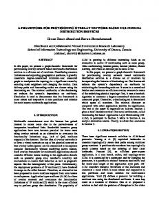
3 Backup Tree Algorithm We assume that n nodes of an overlay network (vertices) are interconnected by a mesh of m links (edges). For a full mesh with n vertices, the number of edges is m = n (n-1) / 2. However, usually application level multicast approaches do not establish full meshes, but only certain links between nodes. Due to existence of firewalls we have to assume that not each node can connect arbitrarily to any other node. On the other hand, in most approaches each node tries to establish a certain number of links to other nodes. This also improves the reliability of the overlay network. Out of the finally resulting mesh a huge number of possible multicast delivery trees could be calculated. We assume that multicast delivery trees are spanning trees consisting of n vertices and n-1 edges. Since a tree identifier is limited to a certain size, we need an algorithm that restricts the number of possible multicast delivery trees. We propose to restrict this number to n and to compute n-1 backup edges that can replace each of the n-1 edges of the default multicast tree in case of link breaks or congestion. We compute a backup edge from the set G-T (G: set of edges of the graph, T: set of default multicast tree edges) for each edge of the default multicast tree T. Replacing each of the n-1 edges of T by its corresponding backup edge results in n-1 backup multicast trees. The default multicast tree and the n-1 backup multicast trees result in n alternative multicast delivery trees that can be used for packet delivery over a multicast overlay network. In the following we present the algorithm for the independent mode and we assume that each node knows the default multicast tree. There are several ways how to build a default multicast tree such as multicast routing protocols or minimum spanning tree algorithms. Assuming Prim’s minimum [4] spanning tree algorithm with a complexity of O (m log n), one could naïvely calculate n-1 minimum spanning trees for the n-1 graphs G-ei with ei = edge i of the minimum spanning tree, i = 1, …, n-1. The complexity for calculating n-1 backup multicast trees is O (m n log n) in this case. Our intention is not to determine backup multicast trees with optimal link weights, but those that can be calculated at low cost. We achieve a complexity of O (m log n). Another goal is to determine a rather small set of edges that can serve as backup edges for the edges of the default multicast tree. Moreover, we select backup paths in such a way that they have minimum overlap with the default path. The idea for the backup tree algorithm is taken from the observation that a backup edge can repair all other edges of the default multicast tree with which the backup edge forms a cycle. For example, in Fig. 1 edges (C, H), (H, L), (C, E), (E, I), (I, M), and (M, N) can be repaired by edge (L, N). On the other hand, edge (S, A) can not be repaired. A broken edge of the default multicast tree can either be replaced by a backup edge that is not in the default multicast tree or it can not be repaired at all. In the following we assume that the complete graph is stored in a linked data structure of vertices with pointers to their edges and neighbor vertices as it would result from a minimum spanning tree calculation. We also assume that the default multicast tree edges are labeled as such and that each vertex has a vertex identifier. First, we calculate the path from the root to each vertex in T and store this path with
A Backup Tree Algorithm for Multicast Overlay Networkss
1433
each vertex. Then, we calculate for each edge in G-T the resulting path from the root via the first vertex to the second vertex of the edge. That path is called backup path for a certain vertex, since it allows reaching a vertex via an alternative path than the default path along the default multicast tree. The backup paths can be used to reach vertices in case of edge failures. For example, edge (L, N) stores backup path SACHLN (S→L, N), while (N, L) stores backup path SACEIMNL (S→N, L). Edge (A, D) stores backup path SAD (S→A, D), while edge (D, A) stores SABDA (S→D, A), which will later be detected as invalid, because A occurs twice in it. A vertex can be reached via the path along the default multicast tree and via one or more backup paths. For example, node L can be reached via the default multicast tree, but also via two backup paths going via J or N. Moreover, we calculate and store for each edge in G-T at which node the path along the default multicast tree and the backup path to reach a particular node begin to differ. For example, node L can be reached via backup path SACEIMNL (S→N, L) and the default multicast tree path SACHL (S→L). These two paths begin to differ in the fourth vertex (E/H), but the first three vertices (SAC) are identical. Therefore, we store the value 3 (called common path length) with the backup path (SACEIMNL/3) at (N, L).
M SACHLNM/3
E SACHLNMIEC/3
S
SACHLNMIE/3 N
SACHLNMI/3
I A SADBA/2
SACEIMNL/3 SACHLN/3
SABDFJLHCA/2 C
SAD/2 B
SABDFJLHC/2)
SADB/2 SACHLJFDB/2
SABDFJLH/2 SACEIMNLH/3 L H
D
SABDGKFD/4 SACHLJFD/2
SACHLJ/2 SABDFJL/2
SABDFKGD/4 F G
SABDFK/4 SABDGKF/4
SABDFKG/4 SABDFJKG/4
K
SACHLJF/2 SABDGKJF/4 SABDGKJ/4 SABDFJK/4
J
Fig. 1. Backup Multicast Tree Construction
Next, we copy the backup paths to the leaf edges of the default multicast delivery tree. We extend each copied backup path by that node of the leaf edge that is closer to the root of the tree. If a leaf edge connects to two edges of G-T, we only keep the backup path with the lowest common path length. For example, edge (H, L) connects to two edges in G-T: (N, L) and (J, L). We consider backup path SABDFJLH/2 (copied from (J, L)) as the best choice and only keep that one, but we remove SACEIMNLH/3 (copied from (L, N)). After processing all leaf edges we consider these as labeled. We have then to process all other unlabelled edges in T in the sameway as the leaf edges. After processing leaf edges in the first round, edges (D, F), (D, G), (C, H), and (I, M) are processed in the second round. Basically, the backup paths are copied towards the root of the tree. For edge (D, F) the backup path copied from edge (K, F), i.e. SABDGKFD/4, is copied, but becomes removed, because the other
1434
T. Braun, V. Arya, and T. Turletti
backup path (SACHLJFD/2) from edge (F, J) has a lower common path length (2 vs. 4). In a later round, edge (A, C) is considered. Only the backup path copied from (H, C) is appropriate (SABDFJLHCA/2). The other one copied from edge (C, E) SACHLNMIECA/3 contains C twice and must therefore be removed When edge 1 (S, A) is considered, all backup paths from edges (A, C) and (A, B) contain A twice. Therefore, (S, A) can not be repaired and is marked as not repairable. Fig. 1 shows the final result of the algorithm. A performance evaluation can be found in [5].
References 1.
2. 3. 4. 5.
H. T. Kaur, S. Kalyanaraman, A. Weiss, S. Kanwar, A. Gandhi: BANANAS: An Evolutionary Framework for Explicit and Multipath Routing in the Internet, ACM SIGCOMM 2003 Workshop on Future Directions on Network Architectures (FDNA), August 25-27, 2003, Karlsruhe / Germany. Y. Chu, S. Rao, S. Seshan, H. Zhang: A Case for End System Multicast, IEEE Journal on Selected Areas in Communications, Vol. 20, No. 8, October 2002 S. Banerjee, B. Bhattacharjee, Ch. Kommareddy: Scalable Application Layer Multicast, ACM SIGCOMM 2002, Pittsburgh / USA, August 19-23, 2002 R. Prim: Shortest Connection Networks and Some Generalizations, Bell System Technical Journal, Volume 36, pp. 1389-1401, 1957 T. Braun, V. Arya, T. Turletti: Explicit Routing in Multicast Overlay Networks, INRIA Research Report 5397, November 2004