Abstract. A diagnostic system is developed to detect large errors, such as a dipole field defect of a magnet and monitors to be adjusted in a particle accelerator.
1155
A, Beam Diagnostic System for Accelerator Using Neural Networks Yuko Kijima , Katsuhisa Yoshida , Manabu Mizota Accelerator Projects, Nuclear Fusion Development Dept., Mitsubishi Electric Corporation Marunouchi 2-2-3 , Chiyoda-ku , Tokyo , 100 , Japan Keiichiro Suzuki ALSCIENCE & UNIX Division , CSK Corporation
Abstract A diagnostic system is developed to detect large errors, such as a dipole field defect of a magnet and monitors to be adjusted in a particle accelerator. It makes use of the fitting method (1)‘, based on an equation of ideal beta&on oscillation, and makes an evaluation function with respect to orbit distortion. These errors are identified from the pattern of evaluation function, using neural networks and a rule system. In a recognition test study, the correct answer was obtained in 95% of the cases having two errors or less.
pattern of evaluation function Fin is complex. We hence apply the pattern recognition technique and resort to the neural network method. To test this system, we use the ring parameters and some measured C.O.D. data of the SR ring at SORTEC(2). This SR ring is a 1GeV electron ring made of 8 FODO cells and equipped with 8 position monitors. Fin
n=3
n=3
Fin
1. INTRODUCTION Recently accelerators are being const~cted for industrial and medical applications, such as lithography, cancer therapy. For these various applications, easy commissioning and operation are required. We are developing a rapid commissioning and automatic operation system. As a first step, we constructed a system which give us useful information about large errors at commissioning time. The fitting method is applied to find large errors, taken to be gross deviations in the magnet dipole field and beam monitor measurements. (Hereafter referred to as “errors” as distinguished from monitor “resolution” characterizing ultimate performance.) Value Fin is formed to estimate the deviation of the measured beam position from the fitted one,
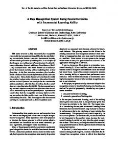
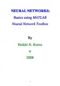
where Xj is the calculated beam position in j-th monitor, xj is the measured one, r is the monitor resolution and n is the number of measurement used in the fit. For a properly selected r, Fin” 1 when there are no large errors, and Fin>>1 when a large error occurs. In the case of one large error, We find the following simple rules . [I] The discontinuity of orbit occurring between monitor j and (j+l) leads Fin>>], with index i which is within (n-l) upstream of j. [2] The monitor ‘error leads Fin>>l. with index i which is within n upstream of j. Figure 1 and 2 show examples of such patterns. In practice there are plural errors. It is very difficult to make rules for them, because the connection betwtlcn errors and the
Figure 1. Exan@e of Fin (in the case of dipole defect between monitor 2 and 3)
Figure 2. Example of Fin (in the case of error in monitor 5)
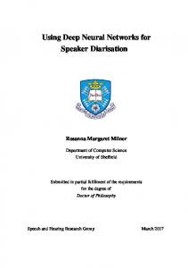
2. SYSTEM ARCHITECTURE This system infers the monitor error or the section where the magnet errors occur, from the measured beam position, by using neural networks and a rule system. Figure 3 shows the system architecture which consists of independent units summarized below. (1)Calculation by fitting method - calculate the evaluation function Fin from the measured data of beam position monitors. (2)Neural networks - infer the location of the error from patterns of the evaluation function, learn patterns. and store many kinds of networks. (3)Rule system -judge the output of networks and control the networks (2) Neural NetWCdt.9 (1) Calculation by + Fitting Method
(3fiJI
Figure 3. System architecture
Rule System
1156
3. NEURAL
(2) The error siz.. is set to cause an orbit deviation of about 5 or 10 times. (3) Test casesconsist of the case of one error, two errors, and more than three errors. Each set of networks is tested in 24 cases for 1 error, 16 cases for 2 errors. and 6 cases for more than 3 ermrs. (4) If the output value of network is exceeds 0.5, the output is considered to be the answer given by the network. The result of the recognition test is shown in Table 2.
NETWORKS
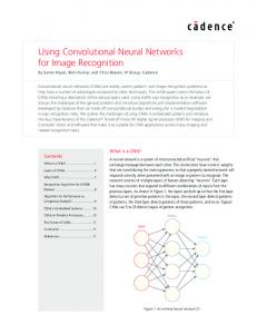
3.2 Networks The learning algorithm is back propagation illustrated in Figure 4. In this procedure, the strength of connection between 2 neurons are changed to reduce the difference between a desired pattern and the output data. A mean of the difference squared describes the progress of learning. haming is completed if the mean is less than 0.08 and terminated if the number of learning exceeds 5000 times. ‘Ihe neuron is composed of an input layer, one hidden layer and an output layer. Input to the networks is the evaluation function value and the output indicates the probability of errors occurring. As the model accelerator of this test has 8 monitors, we set 8 neurons in input layer and 16 in output. Hidden layer is chosen to involve 24 or 32 neurons, in view of a speedof learning and recognition accuracy. NEURAL NETWORK
o”put
Table 1. Leaming pattcm NO. -i-
r
I
L 4
RegulateWeight BesveenEachNeurons Figure 4. Structure of network
~o&riso”~ I
Calculate Errors
3.2 Pattern Learning We made many networks for a recognition test. Pattern learning is set up on some combinations of magnet or monitor elTo#rs.It is assumed that the beam orbit is as large as the beam acceptance of the ring and monitor resolution is ignored. Many networks arc completed in learning case of one error, two ermr~ and additional learning, changing the neumn number of hidden layer and number of fitting. Some networks work well for monitor errors while others are suited to magnet errors. Table 1 shows the learning pattern of networks.
3.3
Recognition Test
The recognition test was performed using the simulator for COD analysis. The test conditions an: the following. (1) The ermrS are assumed to be similar types used in pattern learning. The monitor resolution is taken to bc 0.5mm r.m.s..
1 additional
pad
hidden
1 none 1-M or l-BM OTl-CM none 1-M or l-BM or l-CM 2 none 3 2-M or 2-BM or 2-CM none 2-BM or 2-CM or 1-BM,CM 4 2-BM or 2-CM 1-Mar I-BMorl-CM 5 none l-M.BM or I-M,CM 6 ix 2-BM 2-BM or 2-CM 2-M or 2-BM or 2-CM 7 7n-A n: numDer * oxz errors A: error point ( Mmoniru, BM:hending magnet. CM:correctormagnet)
Desired
_
pattern
Table 2. :co gnition test (%) Network Number kind of error M. correct misrecog field correct misrecog M. correct misrecog field correct misrecog M. correct misrecog 1 field correct misrecog: 1) Network numhelrir ldicatesNt . in Table 1 2) ‘correct’ or ‘misrecog’ is the correct or incorrect answer of networks. 3) The figures indicate the rate of the corrector incorrect answerto siluatederrors
24 32 24 24 24 24 24
7 0 9 81
6 0 0 70
7 0 0 69 - 6
4) N indicates number of CYTO~S.
The pmperty of networks is following. (1) In the case of 1 error, networks which learn 1 error recognize comctly, and give little misrecognition. (2) In the case of 2 error, the rate of correct answer is inferior to the case of one error. The networks which learn 2 errors work with high rate of correct answer. (3) In the case of more than 3 ermrs,the rate of the correct answer is low. However, depending on the network used. it is possible to answer about 60% correctly. The rate of correct answer depends on what the networks have learned. When plural errors exist concurrently, some networks identify many candidates which include misrecognition. It should be able to choose the correct answer out of them. The networks which have learned the case of only one error is effective in finding one big error, even when plural errors exist.
1157 AB/B=0.002 in BM2. From figure 6 we set random error
4. Rule System
equal 0.5mm r.m.s..
4. I Outline of rule system The rule system is applied in order to judge the correct answer from many candidates. The function of the rule system is the following. - Rules choose the networks to use. - Rules decide the correct answer from the network outputs. - If the rules cannot decide them, the rules call upon different
Test pattern and result are shown in table 3. From these results we find some consideration. In the case with two or fewer errors in the ring with 8 position monitors, (1) The result given rank A is correct in more than 95%. The system detect wrong monitors or the section where errors occur in mote than 60% of situated errors. (2) The result given rank B is correct in more than 70%.
dW0fk.S.
- Rules give somlepreferential ranking to these results. The rule system procedure is as follows. (1) input the fitting evaluation value, and load 3 kinds of basic networks. (2) distinguish the candidates which give more than 0.5. (3) determine the candidate selected by every network to be the n3ult. (4) save the other candidates for next network analysis. (5) choose the appropriate networks from the characteristic of nextcandidate. Above procedure is repeated until the following conditions are met. - There are no mote candidates left to be tested - There are no1more networks left to test The result which the system determines the first cycle is rank A. Ranks B,C and D are determined on the secondthird and fourth or later cycles “pectively.
4.2 Result The total system performance is examined using measured data and C.0.D data simulated from ring parameters at the SR ring of SORTEC. We consider the following errors which cause the horizontal deviation on simulation. (1) Bending magnet alignment ctror position AXg AZg I’OkItiOn 0 By
dipole field defect AB/B (2) Quadrupole magnet alignment error position AXQ rotation BQ y (3) Corrector magnet kick angle ecx wrong measurement AXM (4) Monitor The test is carried out some combination of errors mentioned above. In addition to these, it is examined by measured data when the dipole field defect LIB/B of BM is given. Figure 5 shows the measured C.O.D. data of SORTEC in the case of no defect, and figure 6 shows the case of dipole field defect
AXQ=~
AXQ=~
AB/B
2M-3M
AXM
1)M
AB/B=O.O05
x
-5.0
10.
COD-X(mm)
20.
30.
40.
50.
40.
Figure 6 C.0.D data at SORTEC tin the case of dipole field defect in BM2) 50.
Location (m)
20.
30.
5. Conclusion It becomes clear that the developed system is effective for the following. (1) It can detect large et-tots with significant probability. (2) Even if there are plural errors, the most probable candidate is selected by using neural networks and a rule system. The results depend on the learning patterns of neural networks. We should improve the learning method and the patterns used to increase the rate of recognition. The present system assumes that beam is circulating and C.0.D data is available. In the future, this should be extended to earlier commissioning stages and include survey data as well as the magnet factory data.
6. References 1. D.Brandt and A.Verdier, Exhaustive Search of Field Defect Compensation and Reading Errors in A.G. Machines , 1st EPAC (RomeJune 1988) 2. Y.Yamamoto et al. ,Performance of the 1GeV Electron Storage Ring for the Synchrotron Radiation Source at SORTEC ,2nd EPAC (NiceJune 1990)
AXM =5
3M-QM2M-3Mm l3hGlM l3MJkl 2M M 1M 4M-5M 3M
ecx =3
AB/B=0.002 -2MJ.M
4M5M & 6M
1M 8M
iziMi&lu 9l!ddhlu 4M