model with additional biologically plausible sensory information. Figure 3: Prototype active whisking module using. BioMetal to protract an artificial vibrissae.
A Biologically Inspired Haptic Sensor Array for use in Mobile Robotic Vehicles. Martin J. Pearson∗ , Ian Gilhespy∗ , Chris Melhuish∗ , Ben Mitchinson, Mokhtar Nibouche∗ , Anthony G. Pipe∗ , Tony J. Prescott ∗
Intelligent Autonomous Systems laboratory,University of the West of England Adaptive Behaviour Research Group, University of Sheffield Abstract
The periphery of an artificial whisker sensory system is presented. It has been developed by modelling the structure and behaviour of real rodent facial vibrissae. The artificial vibrissae have been formed using composite materials and have the ability to be actively moved in a manner analogous to natural whisking. The sensory apparatus of real vibrissae has been modelled and implemented using micro strain gauges and Digital Signal Processors. The primary afferents have been modelled using empirical data taken from electrophysiological measurements, and implemented in realtime using a Field Programmable Gate Array. Pipelining techniques were employed to maximise the utility of the FPGA hardware. The system is to be integrated into a more complete whisker sensory model, including neural structures within the central nervous system, which can be used to orient a mobile robot.
1.
Introduction
Rodents can orient themselves and discriminate between surface textures using their array of mystacial vibrissae, or facial whiskers (Carvell and Simons, 1990). The vibrissae are the visible ‘front end’ of a sensory system which involves the interaction of numerous neural structures throughout the Central Nervous System (CNS) of the animal (Kleinfeld et al., 1999). Ultimately the mechanical deformations of the vibrissal shaft, as it interacts with the environment, are translated into information which the CNS can interpret and upon which generate appropriate action selections. Any attempt to understand how the CNS interprets this information first requires a suitably accurate model of the translation of mechanical deformation of the vibrissal shaft into neural code. Biologists can either take measurements of the gross behaviour of large groups of neurons from the brains of awake, naturally behaving animals or from individual, or at least smaller groups of neurons, if the animal is sedated and constrained. The principal advantage of the latter technique being that very controlled
stimulus can be presented to the vibrissae. The former technique, however, reveals details of neural interactions which are suppressed by the chemical action of the sedatives used in the more controlled experiments. Using data collected from both these techniques, models can begin to be constructed of various parts of the sensory system. By implementing these models and embedding them onto a mobile robotic platform, the model is tested thoroughly as it will be operating in a real-world, real-time environment. This will inevitably highlight weaknesses and perhaps even reveal engineering solutions which may assist the work of the biologists. The potential applications for such a sensor array in the field of mobile robotics includes the rapid orientation in confined, dark or visual occluded environments, for example, to assist with search and rescue operations following the collapse of buildings or mines. It also does not require the illumination of the environment to extract information, therefore it has a low power consumption and the ability to move covertly. The approach taken in this work differs markedly from previous whisker based robotic sensor systems (Russel, 1992), (Kaneko et al., 1998) which adopted a more abstract engineered interpretation of the whiskers. We have taken a much more biologically inspired approach, adopting instead a philosophy much more akin to the ‘Brain Based Device’ approach (Krichmar and Edelman, 2005). This is the context within which the Whiskerbot project is based and this paper details the important initial work of extracting information from an artificial vibrissae array which has a sufficient level of biological plausibility and sensory richness to derive a more complete model of this tactile sensory modality.
2.
The Vibrissae
2.1 Background The vibrissae of a rodent can be broadly classified into 2 classes; micro and macro (Brecht et al., 1997). The macro vibrissae are larger and are more popularly identified as the ‘whiskers’ of an animal. The micro vibrissae are much smaller and tend to oc-
cupy the more rostral and caudal areas of the snout. The composition of all the vibrissae is very similar to hair, a solid protrusion of the protein Keratin deposited into a regular structure, which tapers towards the tip with a characteristic curvature. It has been proposed that the two species of vibrissae contribute different specialist functionality to the sensor array (Brecht et al., 1997). It is reasonable to suggest that the longer macro vibrissae are used to ascertain the coarse spatial features of the environment surrounding the head of the animal, whilst the micro vibrissae are more suited to discriminating much finer spatial features, more commonly referred to as texture. What has also been demonstrated is that the macro vibrissae are independently capable of discriminating relatively fine textural features as well as detecting object proximity and determining gross shape (Brecht et al., 1997). This multi functionality, and the simple fact of their larger physical size, led us to model the macro vibrissae in our initial prototype.
Figure 1: The two part aluminium moulds used to form the composite artificial vibrissa
2.2 Artificial vibrissae
We have included the characteristic curvature and tapering observed in rodent vibrissae by machining an aluminium mould to form stereotypical composite vibrissae (see Fig.1). Two pairs of diametrically opposing micro strain gauges were bonded to the periphery at the base of the artificial vibrissae. The configuration of the gauges is such that deflections of the vibrissal shaft, when clamped at the base, will generate a proportional 2 dimensional strain measurement vector. This differs from Darwin IX (Seth et al., 2004) as we intend to explore the role of vibrissae deflections in both planes. We also wish to measure the ‘DC’ component of vibrissae deflections which is not possible using the electret microphone system of Amouse (Fend et al., 2004). The gauges used limit the minimum diameter of artificial vibrissae to 1.5mm, this is approximately 7 times greater than the cross sectional diameter at the base of the largest rat vibrissae. Consequently the length of the artificial vibrissae has also been scaled, however, only by 4 times that of a real vibrissa. This difference in scaling was required in order to maintain an appropriate rigidity of the artificial vibrissae to generate strong responses from the strain gauges. A selection of artificial vibrissae is shown in Fig.2, detailing the various materials with which we have been experimenting. The dynamic and mechanical characteristics of rodent vibrissae have been quantified (Hartmaan et al., 2003). Again, due to the compromise between the desired flexibility of the vibrissae, as measured in the biology, and the stiffness required by the engineers to generate strong signals from the strain gauges, our artificial vibrissae only approximate the dynamics of real rodent vibrissae.
Figure 2: A selection of the artificial composite vibrissa formed using the curved mould of Fig. 1 and a straight mould. Experimenting with different materials
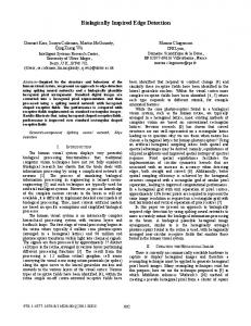
2.3 Active whisking The ability of rodents to actively move their vibrissae, a behaviour known as whisking, has been suggested as highly instrumental in extracting both textural and spatial sensory information (Carvell and Simons, 1995). The ability to whisk the artificial vibrissae has also therefore been implemented in this model, a photograph of the first prototype is shown in Fig.3. The intrinsic muscles of the rodent facial musculature have been implemented usc Using a wire, shape metal alloy called BioMetal . ing an electrical current to heat the wire causes the material to contract generating a small linear force
which, when translated through a simple pulley gearing, pulls the vibrissae forward (protraction). When the current is switched off, the wire cools and begins to contract, however, to increase the retraction rate of the vibrissae a small spring is used. This is analogous to the elasticity of the skin covering the mystacial pad (or cheek) of the animal (Berg and Kleinfeld, 2003). The BioMetal was employed due to the simplicity of the required control electronics and for its compactness in size and weight. This was very important as we are building an array of such vibrissae to be mounted onto a mobile robotic platform with limited physical space, power and processing resources. To measure the angle of the vibrissae during a whisk cycle, an optical shaft encoder has been added (not shown in Fig.3). This closes the feedback loop for the BioMetal drive electronics and provides the neural model with additional biologically plausible sensory information.
3.
The Follicle Sinus Complex (FSC) model
3.1 Background Each of the vibrissae of a rodent originates from a sinus in the skin of the mystacial pad. Within this sinus is a structure which encapsulates the base of the vibrissae called the follicle. The follicle consists of a number of sub-structures and is anatomically quite complex as shown in Fig.4. Situated within these sub-structures are large numbers of cells which are sensitive to mechanical deformation, hence called mechanoreceptors. There are a variety of species of mechanoreceptor found in the follicle which in turn excite the Primary Afferents (PAs) that innervate the follicle, leaving via the Superficial and Deep Vibrissal Nerves (SVN/DVN). A principle classification metric for these PAs is how rapidly they adapt to stimuli; for example a step input stimulus may invoke activity from a particular PA for 20 milliseconds before that activity reduces back to zero, whilst another may remain active for a much longer period of time in response to the same stimulus. PAs which rapidly adapt to the stimulus (former description) are consequently classified as Rapidly Adapting (RA), where as the latter are Slowly Adapting (SA) (Lichtenstein et al., 1990).
Figure 3: Prototype active whisking module using BioMetal to protract an artificial vibrissae
2.4 Sensor array When a rodent comes into close proximity with an object, it is unusual for only a single vibrissa to make contact with that object. In fact behavioural experiments demonstrate that the animal will attempt to make contact with as many of it’s vibrissae as possible when an interesting object is encountered (Krupa et al., 2001). This suggests that the role of the vibrissae as part of an array is an integral feature of the sensory modality. We intend to build multiple instantiations of the actively whisking artificial vibrissae units and place them onto specialised sensor chassis. Each chassis will hold 6 vibrissae, arranged as 3 pairs of opposing units representing the vibrissae protruding from opposing mystacial pads. Ultimately we plan to build 3 such chassis and stack them upon each other to form two 2 dimensional arrays of 9 vibrissae (3×3) projecting in each direction.
Figure 4: Comparative cross-section of rat and cat follicle c (Ebara et al., 2002) . (Reprinted with permission of Wiley-Liss, Inc., a subsidiary of John Wiley and Sons, Inc.)
un INPUT: Mechanical Variable
bu n
b
wn
xn
yn
Gain DirectionalResponse
Non-linearity
Saturation Injection Noise
k
1
+ +
ResetIntegrator
>=
Adaptation toS timulus
zn
DecayConstant
Membrane Threshold
OUTPUT: Spiketrain
vn
-
1 s
+
a Max.Spikingrate
Stimulus Memory
Comparator Integrate-and-fire
Figure 5: Functional block diagram of the proposed mechanoreceptor model(Reproduced from (Mitchinson et al., 2004))
3.2 The mechanical model We have modelled two types of PA to represent the two extremes of the adaptation behaviours. The mechanoreceptors that excite the PAs, are located at different depths within the follicle which consists of solid membranes encapsulating elastic sheaths. The location of the cells within the follicle will effect how the mechanical deformations of the Vibrissal Shaft (VS, see Fig.4) are translated. Cells in the Mesenchymal Sheath (MS) outside of the rigid Glassy Membrane (GM), for example, will effectively receive the derivative of the force which would be experienced by cells located within the Inner and Outer Root Sheath (IRS/ORS) (Mitchinson et al., 2004). This mechanical differentiation has been modelled using an analogous network of mass-spring-dampers, the strain in the springs between rigid sub-follicle membranes representing the mechanical force experienced by the mechanoreceptor.
3.3 The mechanoreceptor model The mechanoreceptor models themselves are simplified functional representations of large groups of actual cells. Indeed what are actually being modelled are the PAs that are excited by the mechanoreceptors, translating this excitation in the form of spike trains to the trigeminal sensory complex (Brain stem). However, for clarity we refer to a single model as a single mechanoreceptor of a particular species with an associated Most Effective Angle (MEA) of sensitivity to the direction of mechanical deformations in the vibrissal shaft. When the vibrissae bends in a certain direction, the mechanoreceptors with MEAs 180◦ to the direction of bend will become maximally excited due to the pivot point at the sinus. This directional sensitivity has been modelled along with a number of other features, as shown in Fig.5, such as adaptation to stimulus, saturation of activity
and a simple leaky-integrate-and-fire model to translate the cell activity into a train of discrete spike events.
3.4 Testing The parameters for the mechanical model were derived using anatomical measurements (Rice et al., 1986) and, where the data was unavailable, a degree of approximation. The various mechanoreceptor parameters were tuned to match real electrophysiological data taken from the primary afferents of sedated rodents during passive and active (induced) whisking (Szwed et al., 2003). The models proved to be of sufficient robustness to repeatedly reproduce good correlation with the empirical biological data in response to different stimuli.
4.
Hardware and communications
4.1 FSC model reduction The model described in the previous section was developed and implemented using software packages and a desk top Personal Computer (PC). To translate this model into an embedded solution required us to adopt a number of constraints and further model simplifications. The integration period of the software model was approximately 1µS, i.e., an update rate of 1MHz. The number of mechanoreceptors modelled was in the region of one hundred per follicle utilising a number of computationally expensive mathematical software functions, all implemented using floating point arithmetic. Simulations of the model by the biologists using a reduced update rate revealed that an acceptable amount of model degradation was experienced with update rates as low as 10KHz. The computationally expensive operation of updating the mass-spring-damper based mechanical model of the FSC was reduced to a pair of second order Infinite Impulse Response (IIR) filters. The two filters represent
the mechanical translation of the vibrissae induced deformation of the follicle on either side of the glassy membrane. The number of mechanoreceptors which have been modelled in the embedded system was initially arbitrarily chosen as 40 per follicle. This figure was later found to be almost optimal with regards to the maximum number that could be modelled in realtime by the system. The MEAs of the mechanoreceptors could be uniformly distributed around the follicle or, as is the case in the biology, be concentrated, thereby creating regions of increased sensitivity for vibrissal displacements of specific orientations.
4.2 Development The TMS320F28xx series of Texas Instruments Digital Signal Processors (DSP) were initially chosen to implement the FSC and mechanoreceptor models as they have the advantage of on-chip peripheral modules such as an Analogue to Digital Converter (ADC), high speed Serial Peripheral Interface (SPI) and 2 EVent managers (EV) for real-time synchronous performance. This kind of processor has a modified Harvard architecture with dual data and instruction buses for high speed processing. They do not have a hardware floating point unit so floating point arithmetic requires the use of computationally expensive software solutions. For this reason a fixed point number system was adopted using appropriate scaling where necessary to reduce the quantisation distortion that is introduced.
Figure 6: Block diagram of inter-processor architecture. (Inset: functional block diagram of the MechanoProcessor)
Preliminary experiments and calculations revealed that the processing performance of the DSP was inadequate to meet the required specification. Each DSP was required to sample and subsequently model the FSC and mechanoreceptors of 6 vibrissa, i.e., 1 DSP per sensor chassis, every 100µS (10KHz). Instead of distributing the processing between multiple DSPs on each chassis, which increases communications and PCB design overheads, we added a single Field Programmable Gate Array (FPGA) to service the entire array. Fig.6 shows an abstract block diagram of the inter-processor architecture; the DSP on each chassis now samples the 6 vibrissa (using the on-chip peripheral ADC module) and computes the IIR filtering of the FSC model. The filtered mechanical variables (16 bit) from each chassis are passed, via separate SPI buses, to the FPGA, which updates all 720 mechanoreceptor models and sends the resultant spike trains to the ‘brain stem’ using a single SPI bus. The brain stem in this case consisting of a model of the trigeminal sensory complex implemented on a matrix of real-time spiking neural network processor FPGAs (Pearson et al., 2005).
Mechanoreceptor Processing Elements (MPE) (each of which incorporates an SPI input bus) and a single SPI output module. The internal update period of the processor is 100µS to match the DSP sample rate, whilst the output update period is 500µS to synchronise with the 2KHz neural processors modelling the brain stem. The sequencer module, therefore, requires 2 separate synchronisation lines, 10Khz and 2KHz, in order to correctly coordinate the activity of the various concurrently operating modules of the system. Due to the high work demand of this application, the system has been designed to maximise the utility of the available hardware at all times. This has been accomplished using 3 main techniques:
4.3 The MechanoProcessor
3. The entire processor system has been designed to operate as a pipeline itself, allowing all modules to operate concurrently whilst utilising a switched dual memory protocol to maintain data integrity between modules.
The central FPGA modelling all 720 mechanoreceptors has been named the MechanoProcessor (see inset of Fig.6). It consists of a main sequencer module, 3
1. The hardware primitives available on the target FPGA, such as the 18-bit signed parallel multipliers and dedicated blocks of RAM, have been integrated into the design. 2. The individual MPEs have been designed using pipelining techniques to facilitate the parallel operation of as much of the hardware as possible thus maximising the throughput of the system.
The first technique detailed above means that the design is quite ‘sticky’, i.e., it will only work when using a limited range of target FPGAs, in this case the Virtex-II family from Xilinx. However, the advantage of using the hardware optimised multipliers instead of implementing high speed parallel multipliers in the configurable logic array of the FPGA is a significant reduction in ‘real-estate’ requirement. The pipelining of the MPEs means that the various stages of the mechanoreceptor model, detailed in Fig. 5, are actually implemented as separate functional components. Each component receives its input from the previous component, processes it and passes the result to the next component in the pipeline. When the pipeline is fully loaded, each component will be working concurrently on a small part of the overall update algorithm of each mechanoreceptor resulting in maximum hardware utility and a minimum update time period. To maximise the utility of the hardware further the third technique mentioned above, the switched dual memory, allows all modules to operate at the same time whilst introducing a fixed pipeline delay to the overall system. An example operational iteration of the MechanoProcessor would be as follows: (note that each of the modules are operating concurrently which is not reflected in the sequential nature of the list) • The SPI module in each MPE reads data sent from the DSP on the corresponding sensor chassis and stores this information into local input Random Access Memory[0] (RAM[0]). • The first functional component of each MPE sequentially reads the data stored in local input RAM[1], passing the results on through the rest of the pipeline. • The last component of each MPE passes its results to an arbitrated central output RAM[0] which is local to the output SPI module. • Every fifth internal update period (500µS, to synchronise the 10KHz MechanoProcessor to the 2KHz brain stem model) the output SPI module reads data from output RAM[1] and sends this onto the brain stem model. • When all modules have completed an operational iteration and the next synchronisation trigger is received, the memories are switched (or toggled) such that the SPI input modules now write into local input RAM[1], the MPEs read from local input RAM[0] and write to global output RAM[1] and the output SPI module reads from output RAM[0]. This system introduces a propagation delay of one update period between modules, two between the input and output of the overall processor. The advantage gained by having all modules working continuously throughout each update period is that the utility of the available hardware is maximised, again
increasing the overall throughput of the system. The contents of the currently write enabled output RAM block of the output SPI module, is updated by OR’ing the current state of each element with the corresponding new value from the MPEs during each internal update period (100µS). Therefore, any spikes that are initiated by a mechanoreceptor during the 500µS update period of the output module are latched. This reduction in resolution at the output is necessary to synchronise the high frequency peripheral neural processing with the lower frequency neural modelling in the brain stem. The PAs modelled in this system will never actually fire faster than 2KHz so there is no danger of a loss of data using this approach. Simulations of the hardware MechanoProcessor have demonstrated that it can update all 720 mechanoreceptors in 100µS. The SPI interface between each DSP and the MechanoProcessor has been implemented and demonstrated robustly transferring data at a rate of 5Mbps. The SPI between MechanoProcessor and brain stem neural processing FPGA has also been demonstrated transferring data, accurately, at 5Mbps. Therefore, the bandwidths of all inter chip communications channels can comfortably accommodate the required data transfer rates demanded of the system.
5.
Conclusion
The periphery of a biologically inspired whisker based sensory system has been designed and implemented. The form of the mystacial vibrissae has been scaled up and replicated using moulded glass-fibre. The artificial vibrissae have been mounted onto a platform that can sweep them in a manner analogous to the whisking behaviour observed in rodents. To extract sensory information from the vibrissae array, strain gauges were used that can derive a stable, 2 dimensional displacement vector of the vibrissal shaft. This information was used to drive an empirically based model of the follicle sinus complex found at the base of each vibrissa. This model has been developed using software and implemented in real-time using a combination of DSP processors and reconfigurable hardware (FPGA). The biologically plausible output from this system will be passed to an established spiking neuron model of the trigeminal sensory complex (brain stem) for further processing and feature extraction. Ultimately this will become a more complete, biologically inspired, sensory system which will be used to orientate a mobile robot in a real-word environment.
Acknowledgments This work is funded by the EPSRC (Grant number GR/S19639/01). Our thanks is extended to Dr. Kevin Gurney and Prof. Peter Redgrave for their contribution to the overall project.
References Berg, R. W. and Kleinfeld, D. (2003). Rythmic whisking by rat: retraction as well as protraction of the vibrissae is under active muscular control. Journal Neurophysiol, 89:104–117. Brecht, M., Preilowski, B., and Merzenich, M. M. (1997). Functional architecture of the mystacial vibrissae. Behavioural Brain Research, 84:81–97. Carvell, G. and Simons, D. (1990). Biometric analyses of vibrissale tactile discrimination in the rat. Journal of Neuroscience, 10:2638–2648.
Mitchinson, B., Gurney, K., Redgrave, P., Melhuish, C., Pipe, A., Pearson, M., Gilhespy, I., and Prescott, T. (2004). Empirically inspired simulated electro-mechanical model of the rat mystacial follicle-sinus complex. Proc R Soc Lond B Biol Sci, 271:2509–2516. Pearson, M., Gilhesphy, I., Gurney, K., Melhuish, C., Mitchinson, B., Nibouche, M., and Pipe, A. (2005). A real-time, fpga based, biologically plausible neural network processor. In Verlag, S., (Ed.), (accepted for) Proceedings: International Conference of Artificial Neural Networks.
Carvell, G. and Simons, D. (1995). Task and subject related differences in sensorimotor behaviour during active touch. Behavioural Brain Research, 12(1):1–9.
Rice, F., Mance, A., and Munger, B. (1986). A comparative light microscopic analysis of the sensory innervation of the mystacial pad. i. innervation of the vibrissal follicle-sinus complexes. J Comp Neurol, 252(2):154–174.
Ebara, S., Kumamoto, K., Matsuura, T., Mazurkiewicz, J., and Rice, F. (2002). Similarities and differences in the innervation of mystacial vibrissal follicle-sinus complexes in the rat and cat: a confocal microscopic study. Journal of Comparative Neurology, 449:103–119.
Russel, R. (1992). Using tactile whiskers to measure surface contours. In press., I., (Ed.), Proceedings of the 1992 IEEE International conference on robotics and automation, pages 1295–1299.
Fend, M., Bovet, S., and Hafner, V. (2004). The artificial mouse - a robot with whiskers and vision. In Proceedings of the 35th International Symposium on Robotics (ISR 2004). Hartmaan, M. J., Johnson, N. J., Towal, R. B., and Assad, C. (2003). Mechanical characteristics of rat vibrissae: resonant frequencies and damping in isolated whiskers and in the awake behaving animal. Journal of Neuroscience, 23(16):6510– 6519. Kaneko, M., Kanayama, N., and Tsuji, T. (1998). Active antenna for contact sensing. IEEE transactions on robotics and automation, 14(2):278– 291. Kleinfeld, D., Berg, R., and O’Connor, S. (1999). Anatomical loops and their electrical dynamics in relation to whisking by rat. Somatosensory and motor research, 16(2):69–88. Krichmar, J. L. and Edelman, G. M. (2005). Brainbased devices for the study of nervous systems and the development of intelligent machines. Artificial Life, 11:63–77. Krupa, D., Matell, M., Brisben, A., Oliveira, L., and Nicolelis, M. (2001). Behaviour properties of the trigeminal somatosensory system in rats performing whisker-dependent tactile discriminations. The Journal of Neuroscience, 21(15):5752–5763. Lichtenstein, S., Carvell, G., and Simons, D. (1990). Responses of rat trigeminal ganglion neurons to movements of vibirssae in different directions. Somatosens. Motor Res., 7:47–65.
Seth, A., McKinstry, J., Edelman, G., and Krichmar, J. (2004). Texture discrimination by an autonomous mobile brain-based device with whiskers. In Press., I., (Ed.), International Conference on Robotics and Automation (ICRA2004), pages 4295–4930. Szwed, M., Bagdasarian, K., and Ahissar, E. (2003). Encoding of vibrissal active touch. Neuron, 40:621–630.