SUMMARY. In this paper, an algorithm of the median-cut quantization (MCQ) is proposed. MCQ is the technique that re- duces multi-valued samples to ...
IEICE TRANS. FUNDAMENTALS, VOL.E83–A, NO.2 FEBRUARY 2000
320
PAPER
Special Section on Intelligent Signal and Image Processing
A Bit-Operation Algorithm of the Median-Cut Quantization and Its Hardware Architecture Shogo MURAMATSU† , Hitoshi KIYA†† , and Akihiko YAMADA†† , Members
SUMMARY In this paper, an algorithm of the median-cut quantization (MCQ) is proposed. MCQ is the technique that reduces multi-valued samples to binary-valued ones by adaptively taking the median value as the threshold. In this work, the search process of the median value is derived from the quick-sort algorithm. The proposed algorithm searches the median value bit by bit, and samples are quantized during the search process. Firstly, the bit-serial procedure is shown, and then it is modified to the bit-parallel procedure. The extension to the multi-level quantization is also discussed. Since the proposed algorithm is based on bit operations, it is suitable for hardware implementation. Thus, its hardware architecture is also proposed. To verify the significance, for the application to the motion estimation, the performance is estimated from the synthesis result of the VHDL model. key words: adaptive quantization, median value, motion estimation, VLSI
1.
Introduction
The median-cut quantization (MCQ) is the technique that reduces multi-valued samples to binary-valued ones by adaptively altering the threshold as the median value. MCQ has been found several applications in signal and image processing so far, such as color reduction and preprocessing of low-power implementation [1]–[3]. The basic procedure of MCQ is as follows: firstly sort given samples, secondly extract the median value, and lastly quantize all samples by using the median value as the threshold. The most significant step is the sorting process. The sorting process has been a principal problem in the area of computer engineering so far. Thus, there are a lot of sophisticated techniques for that [4]. Extracting the median value, however, does not require the complete sorting. Indeed, in order to obtain the median value, the pruning technique of the quicksort algorithm (QSA) is available. This algorithm can extract an arbitrary position value as well as the median value. During the process of QSA, some values are used to recursively divide a given set to two subsets. Such Manuscript received May 18, 1999. Manuscript revised August 12, 1999. † The author is with the Department of Electrical and Electronic Engineering, Faculty of Engineering, Niigata University, Niigata-shi, 950–2181 Japan. †† The authors are with the Department of Electrical Engineering, Graduate School of Engineering, Tokyo Metropolitan University, Hachioji-shi, 192–0397 Japan.
a value is referred to as a pivot. As well as the normal QSA, the question on the pivot selection, however, still exists in the pruned QSA. In the article [5], a solution to select the pivot is shown, and the number of operations is improved. In this paper, we consider developing an algorithm of MCQ which is suitable for hardware implementation. This is motivated from the fact that most of the applications are image and video processing, and they require large amount of computation within a specified time [6], [7]. In order to achieve this purpose, we adopt the pruned QSA. The problem of this approach is how to select the pivot. The method shown in the article [5], however, does not take the quantization into account. From this background, we propose a new pivot selection method for MCQ with the pruned QSA. The proposed method concurrently quantize given samples while searching the median value bit by bit. Indeed, a value consisting of some most significant bits of the median value is used as the pivot during the search process. This bit-level operation leads to an efficient hardware implementation. Since the proposed algorithm can take an arbitrary position value as the threshold, the multiple execution with different thresholds yields a multi-level quantization. The organization of this paper is as follows. As a preliminary, in Sect. 2, we briefly review MCQ and the pruned QSA. In Sect. 3, we discuss the basic idea of the proposed algorithm, and then show the bit-serial procedure. We also modify it to the bit-parallel procedure. The extension to the multi-level quantization is also discussed. The hardware architecture is proposed in Sect. 4. The architecture is simple in the data and control flow. To show the significance, in Sect. 5, the application to the low-bit block matching motion estimation is discussed [2], [3], [7]–[9], and estimate the architecture by some synthesis results from the VHDL model, followed by the conclusions in Sect. 6. 2.
Review
As a preliminary, this section briefly reviews MCQ and the pruned QSA. 2.1 Median-Cut Quantization (MCQ) Let x(n) and y(n) be an input and the output for
MURAMATSU et al.: A BIT-OPERATION ALGORITHM OF THE MEDIAN-CUT QUANTIZATION
321
Step 6: Go to Step 1 until |SCi | = 1 or all elements in SCi equal to each other. Step 7: End. The/an element in SCi is the target. Although the above procedure is described for extracting the median value TM , the target does not limited to it. Indeed, any position in the range from 0 to N − 1 can take the place of the median position M . The efficiency of this procedure highly depends on how to select the pivot xi−1 ∈ SC(i−1) in Step 2. Fig. 1
Pruning technique of QSA.
3.
MCQ, respectively, and let N be the number of samples. Then, the function of MCQ is represented as follows: � 1, x(n) ≥ TM , n = 0, 1, · · · , N − 1 (1) y(n) = 0, otherwise where TM is the median value. Let u(n) be the ordered sequence of x(n) with the increasing order. Then, TM is obtained as follows: TM = u(M ), M = �N/2�,
(2)
where the function �x� means the integer part of its argument x. The threshold adaptively alters according to the distribution of x(n). The sorting process of x(n) is not necessary to obtain TM . It is sufficient to use the pruned QSA, which will be shown in the followings. 2.2 Pruning Technique of QSA Figure 1 briefly illustrates the pruning technique of QSA [4], [5]. We firstly explain the case that the target is the median value TM . Then, we generalize the discussion to any position value. In Fig. 1, SC0 denotes the set of given samples x(n), SCi is the subset of SC(i−1) which includes the median value TM , that is, the candidates, and S¯Ci is its complement in SC(i−1) , that is, SC(i−1) = SCi ⊕ S¯Ci . xi−1 denotes the pivot of the i-th iteration. For extracting TM , the procedure is represented as follows, where M is the median position M = �N/2�: Step Step Step Step
0: 1: 2: 3:
Initialize i, c as i = 0, c = 0. Increment i as i = i + 1. Select an element xi ∈ SC(i−1) as the pivot. Divide SC(i−1) into the following two subsets:
SLi = {x(n) ∈ SC(i−1) : x(n) ≥ xi−1 }, SSi = {x(n) ∈ SC(i−1) : x(n) < xi−1 }. Step 4: Let SCi that is, TM update c as Step 5: Break if
= SLi when c + |SLi | > N − M − 1, ∈ SLi . Otherwise, let SCi = SSi and c = c + |SLi |. SCi = ∅. xi−1 is the target.
The Algorithm
In this section, we consider applying the pruned QSA to MCQ. The key point is the way of selecting the pivot. Indeed, the pivot is chosen as a value consisting of some most significant bits of the median value during the process. Firstly, we propose the bit-serial procedure, and then, modify it to the bit-parallel procedure to improve the throughput. 3.1 Bit-Serial Procedure In this paper, we assume that x(n) is an unsigned integer, and let B and N be the number of bits and the number of samples, respectively. Let us remind the procedure described in Sect. 2.2. The basic idea of our proposed algorithm is based on the following facts: Fact 1: If the number of 1s in MSBs, or (B − 1)-th bits, of all samples is larger than N − M − 1, the MSB of TM must be ‘1,’ otherwise ‘0.’ Thus, by dividing SC0 into SL1 and SS1 according to each MSB, which implies the pivot x0 = TM &2B−1 , it is easily identified which the candidate is, where ‘&’ denotes the logical product. Fact 2: If SSi is not the candidate, then the elements all are necessarily smaller than TM , and should be quantized to ‘0.’ Otherwise, the elements in SLi should be quantized to ‘1.’ Fact 3: Assume that SC(i−1) has been divided into SCi � and S¯Ci with the pivot xi−1 = TM &( ib=1 2B−b ). Then, dividing SCi into SL(i+1) and SS(i+1) according to only the (B −i−1)-th bit corresponds to the �i+1 selection of the pivot as xi = TM &( b=1 2B−b ). Fact 4: The check if SL(i+1) is the candidate or not is achieved by firstly counting 1s in the alreadyquantized samples and on the (B − i − 1)-th bits of elements in SCi , and then evaluating if it is larger than N − M − 1 or not. If not, SS(i+1) is the candidate. For the sake of simplification, we explained the above � facts by using the masked median value xi = i+1 TM &( b=1 2B−b ), which consists of the (i + 1) most significant bits of TM , as the pivot. The pivot, however, may be out of SCi . Precisely, the division according to a bit corresponds to selecting the smallest element x(n)
IEICE TRANS. FUNDAMENTALS, VOL.E83–A, NO.2 FEBRUARY 2000
322
satisfying Eq. (3) as the pivot xi . � i+1 � � B−b 2 . x(n) ≥ TM &
3.2 Bit-Parallel Procedure (3)
b=1
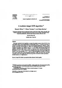
Figure 2 shows the C-like pseudo code of the proposed algorithm. We refer to it as the bit-serial procedure. In this paper, [x]b denotes the b-th bit of x. r(n) and f (n) are one bit variable, where the former contains both of the quantized samples and the b-th bit of candidates, and the latter is the flag representing if it has already been quantized. Although no quantization operation appears in the procedure, flagging in the line 11 implies it. Table 1 shows an example of the process, where B = 3 and N = 8. With the proposed algorithm, N B + N cycles are required for completion. Let us consider applying the procedure to the block processing of size N , and define the throughput by the number of blocks processed per cycle. Then, the throughput is evaluated as 1/N B, because the output process in the line 17 can be overlapped right before the line 5 in the process for the next block, and only N B cycles are required to complete one block.
Some applications require for the throughput to be larger than 1/N B. In the following, we modify the bit-serial procedure so as to improve the throughput. We refer to the technique as the bit-parallel procedure because it operate multiple bits a cycle as a digit in parallel. Note that, in Fig. 2, the check in the line 8 depends only on the result of the previous iteration. Thus, the checking processes in the same iteration can be executed concurrently. Based on this idea, we propose the bit-parallel procedure. Let P be the digit size and a divisor of N , and let K = N/P . We show the algorithm in Fig. 3, where it is assumed that the bit array of the input sequence x(n) is prearranged to a P -bit digit x ˆ(m) such that , [ˆ x(m)]P −p−1 = [x(P · ((m))K + p)]B−� m K �−1 p = 0, 1, · · · , P − 1, m = 0, 1, · · · , KB − 1,
(4)
where ((x))N denotes the integer of x modulo N . For example, when P = 4, the sequence shown in Table 1 is prearranged as follows: x ˆ(0) = ([x(0)]7 [x(1)]7 [x(2)]7 [x(3)]7 )2 = (0111)2 x ˆ(1) = ([x(4)]7 [x(5)]7 [x(6)]7 [x(7)]7 )2 = (0110)2 x ˆ(2) = ([x(0)]6 [x(1)]6 [x(2)]6 [x(3)]6 )2 = (0110)2 .. . x ˆ(15) = ([x(4)]0 [x(5)]0 [x(6)]0 [x(7)]0 )2 = (0000)2
Fig. 2 Proposed bit-serial procedure of the median-cut quantization. Table 1 Example of the signal flow in the proposed method, where B = 3, N = 8 and M = 4. r (b) (n) denotes r(n) in the iteration for the b-th bit, ‘f’ is the flag which implies f (n) = 1 and (·)2 means the binary representation. In this example, the median value TM results in 5 = (101)2 . n 0 1 2 3 4 5 6 7
x(n) 1 7 6 5 2 6 4 0
(001)2 (111)2 (110)2 (101)2 (010)2 (110)2 (100)2 (000)2 c TM
r (2) (n)
r (1) (n)
r (0) (n)
-
f f f
f f f f f f
0 1 1 1 0 1 1 0
5 (1 - - )2
0 1 1 0 0 1 0 0
3 (10 - )2
0 1 1 1 0 1 0 0
4 (101)2
y(n) 0 1 1 1 0 1 0 0 (101)2
The throughput of this prearrangement depends on the peripheral circuit and how to implement it. Hence, we here temporarily give an example. Provided one data per cycle via one bus of width B bits, it can be implemented by a buffer of size N B bits. The throughput meets P/N B blocks/cycle, where P ≤ B. In Fig. 3, the output yˆ(k), the flag fˆ(k) and the intermediate result rˆ(k) are P -bit digits. As a result, the bit-parallel procedure increases the throughput from 1/N B blocks/cycle to 1/KB = P/N B blocks/cycle. Note that the bit-serial procedure can be regarded as a special case of the bit-parallel procedure for P = 1. 3.3 Multi-Level Quantization The pruning technique of QSA described in Sect. 2.2 can be used to obtain any position element of the input x(n). This implies that a Q-level quantization is simply achieved by multiply executing the Q−1 processes with Q − 1 different thresholds TMq given as in Eq. (5). TMq = u(Mq ), Mq = �N q/Q�, q = 1, 2, · · · , Q − 1,
(5)
where u(n) is the ordered sequence of x(n). As a result,
MURAMATSU et al.: A BIT-OPERATION ALGORITHM OF THE MEDIAN-CUT QUANTIZATION
323
dently store the intermediate results. The functions “encode” and “decode” realize the sharing of them. The function “y = decode(x)” decodes the unsigned integer x of (L − 1)-bit into the (Q − 1)-bit digit y such that � 1, x > b , b = 0, 1, · · · , Q − 2. (6) [y]b = 0, otherwise
Fig. 3 Proposed bit-parallel procedure of the median-cut quantization, where “ones” is the function that returns the number of 1s on its argument, and “ext” is the function that extends its 1-bit input to P -bit digit.
For example, when L = 2, decode(0), decode(1), decode(2) and decode(3) return (000)2 , (001)2 , (011)2 and (111)2 , respectively. On the other hand, “x = encode(y)” is the inverse. Note that the procedure described in Sects. 3.1 and 3.2 can be regarded as a special case of the multi-level procedure for L = 1. 4.
The Architecture
Our proposed algorithm is suitable for hardware implementation since the data and control flow are quite simple. In this section, we propose the hardware architecture. As was mentioned before, the multi-level bit-parallel algorithm as shown in Fig. 4 covers the twolevel bit-serial and bit-parallel procedures. Thus, we consider the architecture only for the multi-level bitparallel algorithm. We firstly show the data path architecture, and then the control unit. 4.1 Data Path
Fig. 4 Proposed procedure of the multi-level quantization, where {ˆ y� } and {TˆMq } denote the sets of yˆ� (k) and TMq , respectively. “encode” encodes its Q − 1-bit inputs to L-bit outputs, and “decode” is the inverse function, where [x]p means the p-th bit of x and (·)2 is the binary representation. All of x ˆ(m), rˆ� (k), fˆq (k), dˆq , sˆq and tˆq are P -bit digits.
encoding the results of Q − 1 processes yield the Q-level quantized output. Let Q be a power of 2 and L be log2 (Q). The algorithm of the Q-level quantization can be represented as shown in Fig. 4, where only the bit-parallel type is considered because it covers the bit-serial procedure. Note that each process is not required to indepen-
The architecture of the proposed data path is shown in Fig. 5. It is considered as a synchronous system. Figs. 5 (a) and (b) show the architectures of the top module and the q-th processing element (PEq ), respectively. Each PEq contributes the parallel processing for q in the list shown in Fig. 4. CLK and RST are the clock and reset signals, respectively. UPD, CLR and b are the update signal for Counter C and Register T, and the clear signal for Shift Registers F and R, and the bit pointer of width �log2 (B)�, respectively, which are generated by the control unit as shown later, where �x� denotes the smallest integer larger than or equal to x. All of x ˆ, xˆsyn , tˆq , yˆq , sˆcurq , sˆpreq , rˆ are P -bit digˆ to CLK. its, where x ˆsyn is the synchronized signal of x sˆcurq and sˆpreq correspond to sˆq in the list shown in Fig. 4, where the former is the value in the current iteration, and the latter is that of the previous iteration, respectively. “N − Mq − 1” is a constant. In the proposed architecture, we adopt shift registers for storing fˆq and rˆq , because they remove the logic circuit required for pointing the k-th elements of fˆq (k) and rˆq (k). The timing performance is as follows: • Throughput [blocks/cycle]: P/N B • Latency [cycles]: N B/P + (Prearrangement)
IEICE TRANS. FUNDAMENTALS, VOL.E83–A, NO.2 FEBRUARY 2000
324
(a) Top module
(b) The q-th processing element (PEq ) Fig. 5 Architecture of data path, where hatched box consists of noncombinational logic component. CLK and RST are the clock and reset signals, respectively. UPD, CLR and b are the control signals.
Table 2 Size of registers. N , B, P and L are the number of samples per block, the number of bits, the digit size and the number of quantization bit. P is assumed to be a divisor of N . Component Shift Reg. R Shift Reg. F Counter C Register T Latch X Control Unit
Size of Register (bit) L × N/P × P (2L − 1) × N/P × P (2L − 1) × �log2 (N)� (2L − 1) × B P �log2 (N/P )� + �log2 (B)�
In addition, Table 2 summarizes the size of registers, where P is assumed to be a divisor of N . Note that, when the quantization bit L is one, the number of PEs is reduced to one. Thus, the circuit for “encode” and “decode” is removed. When the digit size P is one, the circuit “ones” of each PE is removed. 4.2 Control Unit Figure 6 shows the architecture of the control unit. The control unit has KB states {Sb,k } for b = 0, 1, · · · , B −1
Fig. 6
Architecture of the control unit, where K = N/P .
and k = 0, 1, · · · , K − 1, where K = N/P . These states translate to another as follows: • Any state Sk,b translates to S0,0 if RST = 0. • Sk,b translates to S((k+1))K ,b if k �= 0 and RST = 1. • S0,b translates to S1,((B−1+b))B if RST = 1. The output functions are defined by • UPD = 0 when S0,b for any b, otherwise UPD = 1. • CLR = 0 when Sk,B−1 for any k, otherwise CLR = 1. The control flow is quite simple because each state translates to either S0,0 or another.
MURAMATSU et al.: A BIT-OPERATION ALGORITHM OF THE MEDIAN-CUT QUANTIZATION
325 Table 3 Estimation from the synthesis results of the proposed MCQ, where B = 8 and CLK is constrained to the period tCLK = 10P [nsec]. “(met)” means no violation is occurred. Digit size P Clock period tCLK [nsec] L=1 Max. data arrival time [nsec] L = 2
Fig. 7
Total cell area ×105 [µm2 ] Net switching power [mW]
Timing chart, where B = 3, N = 8 and P = 2.
An example of the timing chart is given in Fig. 7, where B = 3, N = 8 and P = 2. The threshold TMq and the output yˆq are available when CLR is low. 5.
Estimation
In this section, in order to show the significance of the proposed architecture, we show the timing, area and the power estimation. Firstly, we consider applying it to the low-bit motion estimation [2], [3], [7]–[9], and then the influence of the parameters to the area is discussed. 5.1 Application to Low-Bit Motion Estimation The video compression standards MPEG and H.263 employ the motion compensated prediction coding technique for exploiting the temporal correlation [7]. The motion compensation requires to be preceded by the motion estimation, which is known to dominate most of the computation. Thus, a lot of realization issues has been discussed so far. The low-bit motion estimation technique is a solution to efficiently implement it [2], [3], [7]–[9]. The estimation follows a quantization, and, in the articles [2], [3], [9], it is shown that an adaptive quantization is suitable and MCQ is the good candidate for it. Let Fh × Fv be the number of pixels per frame, and Ft be the number of frames per second (fps). Since the quantization is applied to each macro block, the number of blocks that the quantization has to complete a second is derived as (Fh × Fv × Ft )/N [blocks/sec], where N is the number of pixels in a macro block. The throughput of the proposed MCQ is P/N B blocks/cycle. Thus, the condition for the clock period tCLK is derived as follows: tCLK