J Intell Manuf (2012) 23:2343–2356 DOI 10.1007/s10845-010-0476-2
A case of implementing RFID-based real-time shop-floor material management for household electrical appliance manufacturers T. Qu · H. D. Yang · George Q. Huang · Y. F. Zhang · H. Luo · W. Qin
Received: 28 August 2010 / Accepted: 19 October 2010 / Published online: 4 November 2010 © The Author(s) 2010. This article is published with open access at Springerlink.com
Abstract Radio Frequency Identification (RFID) technologies provide automatic and accurate object data capturing capability and enable real-time object visibility and traceability. Potential benefits have been widely reported for improving manufacturing shop-floor management. However, reports on how such potentials come true in real-life shopfloor daily operations are very limited. As a result, skeptics overwhelm enthusiasm. This paper contributes to the re-vitalization of RFID efforts in manufacturing industries by presenting a real-life case study of applying RFID for managing material distribution in a complex assembly shop-floor at a large air conditioner manufacturer. The case study discusses how technical, social and organizational issues have been addressed throughout the project within the company. It is hoped that insights and lessons gained be generalized for future efforts across household electrical appliance manufacturers that share similar shop-floor. Keywords Radio Frequency Identification (RFID) · Air conditioner · Manufacturing execution · Production management · Material distribution T. Qu · G. Q. Huang · Y. F. Zhang · H. Luo · W. Qin Department of Industrial and Manufacturing Systems Engineering, University of Hong Kong, Pokfulam Road, Hong Kong, People’s Republic of China H. D. Yang (B) College of Automation Science and Engineering, South China University of Technology, Guangzhou, People’s Republic of China e-mail:
[email protected] Y. F. Zhang Key Laboratory of Contemporary Design and Integrated Manufacturing Technology, Ministry of Education, Northwestern Polytechnical University, Xi’an, People’s Republic of China
Introduction Radio Frequency Identification (RFID) technologies offer the capability of automatic and accurate object data capturing and enable real-time traceability and visibility (Chryssolouris et al. 2009). While supply chain logistics industries have mandated the adoption of the technologies and initiated substantial research and development activities (Williams 2004), manufacturing industries have also made practical progress (Huang et al. 2009; Mo et al. 2009). Manufacturers deploy RFID devices to shop-floor objects such as men, machines and materials to capture data associated with their statuses (Brintrup et al. 2010; Ren et al. 2010). Such RFID-enabled real-time visibility and traceability substantially improve shop-floor management in general and Work-In-Progress (WIP) materials management in particular (Huang et al. 2008b). This paper presents a case study of applying RFID for managing material distribution in a complex assembly shopfloor typically within household electrical appliance manufacturers. The thread of discussion starts with a large air conditioner manufacturer with an intention of generalizing the insights and lessons for the whole sector. The operational mode in this air conditioner manufacturing shopfloor has several characteristics. First, production volume is high, production cycle is short, and product structure is complex involving large number of parts and components. Second, production processes are normally sequential involving multiple production stages. Between stages are complicated logistics supports requiring good coordination. Third, globally competitive markets drive rapid new product development and lead to changes in both customer orders and production requirements. Fourth, supplies of parts/components and raw materials vary in terms of quality and service times. Fifth, machine breakdowns and capacities complicate
123
2344
the production planning and scheduling, and in turn have serious impacts on shop-floor material flow. Finally, operators are overwhelmed by production jobs and do not have time to collect and enter operational data, leading to information and communication breakdowns. These production characteristics are common in most of the household electrical appliance manufacturers (De Toni and Zamolo 2005; Perona and Saccani 2004). In order to address the above issues, some enterprise information systems (ERP, MRP, etc.) have been exploited by household electrical appliance manufacturers. For example, this air conditioner manufacturer has implemented high-end ERP (Enterprise Resource Planning) systems in recent years. However, they are confronted with challenges to fully utilize the systems. This is largely due to the information and communication breakdowns between the shop floors and the enterprise decision support systems (DSSs). This has been a prime reason for these manufacturers to look into RFID technologies. Despite widespread enthusiasm, reports on real-life industrial RFID practices, either successful experiences or painful lessons, are very limited. Majority of the reports have been based on preliminary industrial experiments rather than implementations for everyday operations. Skeptics increasingly shadows potential benefits claimed. In order to re-vitalize the effort, this paper presents a real-life case study within our collaborating company. The purpose of this case study is multi-folded. Firstly, this case study shows how RFID-enabled potential benefits come true in a real-life company in terms of improved visibility and traceability, information accuracy, operation efficiency, reduced costs, increased speed and responsiveness, and better product quality control (Clarke et al. 2006; Henseler et al. 2008). Secondly, this case study demonstrates how the case company has dealt with technical, social and organizational challenges in adopting the RFID solutions for shop-floor management. Finally, this case study generalizes a procedure on how RFID solutions can be applied in manufacturing shop-floors for household electrical appliance products with similar characteristics. The generalized procedure contains five steps collected and adapted from successful RFID applications (Ren et al. 2010; Ngai et al. 2010): (1) Analysis of existing business processes, (2) Creation of RFID-enabled manufacturing shopfloor, (3) Implementation of reengineered business process, (4) Champion of good practices, and (5) Reflection for the future. The remainder of the paper is also arranged following the above procedure. “Shop-floor material distribution” introduces the case company, and discusses special features and challenges of its shop-floor material distribution processes. “Creation of RFID-enabled shop floor” discusses how RFID technologies are used for creating a wireless shop-floor. “Project institutionalization” explains how the company has insti-
123
J Intell Manuf (2012) 23:2343–2356
tutionalized the implementation project. “Champion of good practice” exemplifies how implemented RFID-enabled solutions facilitate the daily operations of shop-floor material management. “Evaluation and reflection” evaluates the project in terms of benefits and impacts and reflects on future perspectives. The generalization is summarized in “Summary”.
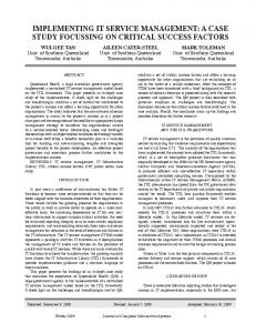
Shop-floor material distribution About the case company The case company is one of the largest air conditioner manufacturers in China. Its products range two categories: home-use and commercial-use air conditioners. Based on the market segments, the company adopts a strategy to focus on the segments for middle- and lower-level consumers. Its key domestic markets are small cities or rural areas in China and overseas markets are mainly within developing countries. Due to this market strategy, products have comparatively lower prices. The company enjoys overall profits through larger outputs and cost control. Its average annual output is over 4 million sets. Therefore, as compared to other household electrical appliances manufacturers, the case company pays more attention on improving the quality of its material distribution to secure an efficient and stable production process. Air conditioner products have complicated structure in the sense that numerous components are involved in the product assembly. However, the case company simplifies its internal production processes into two stages: preassembly and final assembly, while over 90% of the parts and accessories manufacturing are outsourced to suppliers and shareholding subsidiaries. Currently, three assembly workshops of the case company are responsible for three different product lines. Over 5,000 types of materials are used and purchased from nearly 80 suppliers. Materials are stored in 49 warehouses and are distributed to workshops by more than 100 logistics staffs. This case study is concerned with one workshop and its related warehouses. Description of the shop floor A typical shop-floor material distribution process is cooperated by four major functional departments: Production Plan Department for making both production and material requirement orders; Warehouses for storing both materials and final products; Logistics Department for distributing materials to Production Department, and taking the finished products back to warehouses. As can be seen in Fig. 1, production and logistics departments are located inside a workshop, while the other two departments are outside. The production department has two preassembly lines and ten
J Intell Manuf (2012) 23:2343–2356
2345
Production Plan Department
ERP (SAP)
Orders / Status
Workshop Logistics Department
Raw Materials
Production Department
Logistics Manager
Final Assembly Buffer
Final Assembly Lines e
d
identified and replenished, leading to frequent production delay or order changes. The causes of the above problems are: lack of appropriate visibility and traceability functions at key working areas, e.g. order visibility; lack of data synchronization between ERP system and shop floor’s key value-adding points (locations labeled from “a” to “e”).
WIP
Stage 2: Material preparation and delivery Preassembly Buffer Raw Materials
Pre-Assembly Lines c
b
a2
Warehouse
a1
Fig. 1 Workshop layout
final assembly lines positioned in two parallel production areas, with two corresponding buffers located to the left. Buffers and all the logistics operations are managed by the logistics department. Cause and effect analysis for the current process A typical shop-floor material distribution process contains five stages as shown in Fig. 1. This section will conduct confirmatory cause and effect analyses to find out whether and how the RFID facilities are required in the material distribution process. Stage 1: Production and material requirement plan Production plan department makes and releases order in paper-based “multi-copy form” to shop floors. Typical orders include production orders for assembly lines and materials orders for logistics and warehouse departments. In addition, order copies will also be circulated to document office for recording. During the order fulfilling process, all the involved operations and required manufacturing objects (operator, machine and material) are manually matched to order through marking on the paper-form and then input to systems by man. Three problems currently exist: (1) paper-based order is wasteful, and the manual recording process of transaction data is time-consuming, error-prone, and subject to troublesome reprinting when order changes; (2) planned orders are always unachievable due to the various operational dynamics, e.g. machine breakdown or defective material/product; (3) out-of-stock material in warehouse cannot be timely
Material operators at warehouses pick up all the materials based on the received material orders and load to pallets in the afternoon. Logistics workers collect all the loaded pallets from warehouses and deliver to workshops in the next morning. All the finished material orders are manually updated to ERP system by warehouse manager when they are free, normally with a one-day delay. Three problems currently exist: (1) material locating and distinguishing in manual ways is time-consuming, especially for the same type of materials purchased from multiple suppliers; (2) logistics jam at a warehouse gate happens frequently because the logistics works happen in a relatively fixed period; (3) delayed materials consumption information normally leads to untimely replenishment and thus stock-out situations. The causes of the above problems are: lack of Auto-ID tags on material packages, circulating boxes and pallets; lack of data capturing devices at warehouse (“a2”); lack of real-time data synchronization between warehouses (“a1”) and ERP system. These causes are suffered in common in the follow stages. Stage 3: Material buffering Materials delivered to workshops will be stored in preassembly or final assembly buffers first before being replenished to the corresponding lines. Components (WIP) made by preassembly lines will also be stored in final assembly buffer. Two problems currently exist: (1) materials checking in and out buffer involves complex manual data transaction works; (2) real-time buffer information is not real-time available. In case of order changing, buffered materials cannot get efficient handing, e.g. order transfer or re-warehoused. The causes of the above problems are similar as those for warehouses discussed in stage 2, except the data capturing synchronization point will be “b”. Stage 4: Preassembly Logistics workers make their rounds along the preassembly lines periodically, and replenish materials from buffers to lines when the line-side material inventory is below a safety level. The finished WIP will be sent to final assembly buffer.
123
2346
Two problems currently exist: (1) a lot of unnecessary labor costs are wasted on line-side inventory checking; (2) without real-time WIP information, final assembly may start earlier or later, resulting in either production delay or redundant WIP. Besides the basic cause of the lacks of Auto-ID tags on materials and devices at preassembly line (“d”), lacking of synchronization between preassembly line (“c”) and final assembly line (“d”) is the main cause for the above two problems. Stage 5: Final assembly The way of line-side inventory replenishing is similar as that for preassembly line, while the finished final products will be sent back to warehouses instead. Two problems currently exist: (1) the wastes of unnecessary labor costs on line-side inventory checking still exist; (2) logistics manager cannot arrange timely warehousing for final products without real-time output information, resulting in high product inventory at the line’s end. Besides the basic cause of the lacks of Auto-ID tags on materials and devices at final assembly line, lacking of synchronization between final assembly (“e”) line and logistics department is the main cause for the above two problems.
Creation of RFID-enabled shop floor How to create an RFID-enabled manufacturing shop-floor is critical. Scheme for RFID reader deployment and tagging method must be worked out according to the specific characteristics of the manufacturing shop floor. Factors related to both RFID technical solutions and business processes and operations must be jointly considered and matched between each other. The resulting RFID-enabled shop-floor would not only determine the effectiveness and efficiency of tracking and tracing but also acceptability by human operators. For easy demonstration without losing generality, an AUTOM solution put forward in Huang et al. (2008a) will be adopted to explain a general process of creating RFIDenabled shop floor. AUTOM solution is a standard and extensible RFID implementation strategy. It not only owns an open information infrastructure compliant with ISA-95 standards, but also provides a set of advanced yet optional RFID facilities with standard interfaces integrable with other RFID devices (Zhang et al. 2010). Therefore, the approach of creating RFID-enabled shop floor to be discussed in the following is generally applicable when other RFID implementation strategies or devices are adopted, no matter they replace or compliment AUTOM solution.
123
J Intell Manuf (2012) 23:2343–2356
Design of real-time shop-floor information infrastructure The RFID-based shop-floor information infrastructure proposed in AUTOM solution aims to develop an easy-to-deploy and simple-to-use information infrastructure for manufacturing companies to achieve real-time and seamless dual-way connectivity and interoperability between application systems at enterprise, shop floor, work cells and RFID devices. It is consistent with the standard enterprise hierarchy defined by ISA-95 enterprise-control system integration standard (http://www.isa.org), as shown in the left part of Fig. 2. An enterprise hosts one or more manufacturing sites or areas (e.g. factories or workshops), each of which consists of several production lines/cells or storages zones (e.g. assembly lines or warehouses). The operation of a production line involves a variety of production units, whose operations are concerning with both manufacturing resources (e.g. materials, equipments and operators) and their logical combinations (e.g. product assembling). Implementing enterprise information systems to be consistent with this standard hierarchy will ensure the system applicable and extensible. The right part of Fig. 2 illustrates the main technical levels of the AUTOM infrastructure in correspondence to the four standard enterprise levels. The highest level includes those conventional enterprise information systems (EISs), such as ERP, MRP etc, used by enterprise management for making production plans. The three lower levels are RFIDenabled shop-floor information facilities, including shopfloor application system level, RFID-Gateway and Smart Object. AUTOM facilities provide an efficient way for creating a RFID-enabled shop floor. The following subsections will detail the instantiation process. Development of RFID-enabled shop-floor hardware facilities Creation of shop-floor smart objects The first step of creating RFID-enabled shop floor is to convert conventional shop-floor manufacturing objects into shop-floor smart objects through equipping them with AutoID (RFID or barcode) devices. This step is realized in two aspects. The first is to attach the production materials with Auto-ID tags to make them identifiable. The second is to equip value-adding manufacturing resources with suitable Auto-ID readers to track the information of materials being processed. The above two kinds of shop-floor objects are referred to as Smart Objects (SO). Specifically, the materials with Auto-ID tags are called passive SOs, while the manufacturing resources equipped with Auto-ID readers are called active SOs. In AUTOM solution, the creation of passive SO has two sub-steps. The first is to scope the objects to be tracked and the
J Intell Manuf (2012) 23:2343–2356
Production Line Site/Area Enterprise Storage Zone
ISA-95
2347
Enterprise Information Systems (EISs) Adaptor Shop-floor Application system RFID-Enabled Real-Time Material Distribution System Warehouse
Logistics
Final Assembly
RFID-Gateway • Assembly Line • Buffer Area • Warehouse • Logistics
Stationary Gateway Bluetooth
Production Unit / Storage Module Resources Process Segments
Buffer
Portable Gateway
USB
Serial Port
ZigBee
802.11g
Smart Object Active Smart Object • Workstation • Shelf/Storage Unit • Forklift/truck • Data Collection Point Passive Smart Object •Material •Product /WIP • Equipment • Pallet/Container • Personnel
Bar-code Reader Ethernet Hub HF RFID Reader UHF RFID Reader Terminal
Barcode Materials
Barcode
Final Products
UHF RFID Pallets
HF RFID Operator
Fig. 2 AUTOM infrastructure
second it to determine which kind of tag will be used. The case company focuses on the material distribution process which concerns about delivering the right item by the right operator with the right tools in the right quantity at the right time from the right source to the right destination. Therefore, the objects need to be tracked include raw materials, final products, storage locations, circulating boxes, pallets and operators. The tagging of these objects follows the closeloop RFID system application principle advocated in Schmitt et al. (2007): RFID transponders should be attached to those objects which are shipped or moved within a cycle and eventually returns to its point of origin. Therefore, internally used or circulated resources are attached with RFID tags, such as operators, storage locations, shipping pallets and circulating boxes. Since the raw materials and final products in the case company have already used barcode labeling in agreement with other supply chain partners, they are kept unchanged. The WIP in the distribution process will be traced with their containers. Active SOs are installed at those significant value-adding points of a process where passive smart objects are to be tracked. The high-level view of a manufacturing process is a value chain representing how the manufacturer receives raw materials as input and add values to them through various processes to finally get finished products. The value-adding point defined in AUTOM solution follows this concept, referring to the location where an operation happens to drive the state of a material more approaching
finished product. For example, each loading area or trolley for distributing raw materials, each machine or working station for assembling components, each warehouse shelf for storing finished product, are all the possible value-adding points. In the current implementation stage of the project, however, only the entrance points of line-level areas are selected as the value-adding points for installing SOs, such as the beginning of an assembly line and the gate of a warehouse. This is due to two reasons. First, all the assembly lines operate in a continuous production mode. One reader put at the end of the production line could help derive the statuses of all the comprised workstations. Second, for a logistics process combined with storing, loading, transporting and buffering, stochastic mobile data reading and processing may happen anywhere. Therefore, portable RFID-Gateway is applied instead of wastefully equipping each point with an individual SO. Integration of shop-floor smart objects The second step of creating RFID-enabled shop floor is to integrate all the smart objects deployed at shop floors as well as their information. Some RFID solutions lack this level and expose RFID devices directly to application systems, while AUTOM solution puts forward an intermediate level called RFID-Gateway to form loosely-coupled system architecture (Zhang et al. 2010). RFID-Gateway has a hardware hub and a suite of management software which acts as a
123
2348
server to host all the (active) SOs within a certain working area. Through incorporating various drivers of SOs to form a driver library, RFID-Gateway is enabled to work in a “Plug and Play” fashion to newly plugged SO. Heterogeneous SO drivers are wrapped into standard web service interfaces, enabling upper-level applications to use all the devices in a uniform way. The influential range of an active SO (e.g. a RFID reader) is limited, i.e. covering a value-adding point, while that of a RFID-Gateway is the union of ranges of all the hosted active SOs, i.e. normally a work cell or a production line. Despite the key word “RFID”, RFID-Gateway is substantially supported by other technologies, e.g. barcodes, Wi-Fi, PC, PDA etc. There are stationary, mobile and portable RFIDGateways. Stationary RFID-Gateway is placed at a fixed location, such as the gate of a warehouse. Items are moved to the stationary RFID-Gateway to be tracked. A mobile RFIDGateway is installed to a moveable manufacturing resource, such as a forklift truck. Tagged items are not only carried but also traced by the movable recourses during long distance of transportation. A portable RFID-Gateway is a handheld device responsible for distributed item identification within a certain area or along a certain process. Unlike the previous two types, a portable RFID-Gateway is always moved close to the objects by an operator for tag reading. The case mainly uses stationary and portable RFIDGateways. Figure 3a, b show the lab version and onsite version stationary gateways. The former integrates some of the common Auto-ID devices (i.e. active smart objects) being widely used in industry, including Alien ALR-9800 UHF RFID readers, ACS 120 HF RFID readers, and Metrologic MS9535 Bluetooth barcode readers. They could be instantiated or adapted to various onsite versions thorough selecting suitable smart objects according to the specific requirements and conditions of the application sites. Figure 3b shows an onsite RFID-Gateway being used in the warehouse of the case company now. Figure 3c shows the portable gateway which is implemented based on Motorola MC9090-G RFID handheld reader. All the numbered locations in Fig. 1 have been identified as value-adding points and will be equipped with suitable RFID-Gateways. The detailed configurations of these RFIDGateways are listed in Table 1 for better comparison. Development of RFID-enabled application systems The third step of creating RFID-enabled shop floor is to develop shop-floor application system. It normally aims to provide a two-way information channel between shop-floor execution and decision (Zhang et al. 2010). From execution to decision, the system collects real-time information of the smart objects involved in a manufacturing process (via RFIDGateways) for adaptive decision or process control. From
123
J Intell Manuf (2012) 23:2343–2356
decision to execution, the system can transfer and interpret shop-floor decisions into executive work orders that should be followed by smart objects. Such application system normally includes visibility and traceability modules. A visibility module shows the real-time operation status of a specific manufacturing site with graphical user interfaces to facilitate the easy operation of operators. The principle followed is what you see is what you do and what you do is what you see. Traceability is a backend control mechanism which integrates the real-time information captured from different manufacturing stages. Typically, information from different shop-floor locations could be synchronized to enable coordinated operations, while history information of a manufacturing object or process could be retrieved in a later time for failure investigation. Application system is very process-specific, and thus hardly any off-the-shelf system on the market is directly ready for using. The project team customized a RFIDenabled real-time shop-floor material distribution system (RT-SMDS) for the case company. The system is implemented based on service-oriented architecture (SOA) architecture, shown in Fig. 4. Visibility modules are implemented in the form of a set of web explorers to be flexible downloaded and used in RFID-Gateways. Both the traceability modules and a data services are implemented in web services. Data services not only enable standard XML-based data exchanging between application system and its own database, but also implement an ERP Adaptor integrating the RT-SMDS with the case company’s SAP system. The adaptor has four pairs of SAP RFC (Remote Function Call). They are Production Order RFC, Material Order RFC, BOM RFC, and Order Change RFC. The former two are used to get newly made production and material orders from ERP. The latter two are used to modify the released orders if a production order is changed by production plan department. Details of the individual visibility modules and traceability services will be given in “Champion of good practice” with a scenario description.
Project institutionalization Project institutionalization is a process ensuring all the project activities, structures, and values become an integral and sustainable part in the company (http://www.qaproject.org). There are two main phases in this process. First, key institutionalization aspects should be identified and the respective objectives/visions are to be set. Second, objectives of each aspect are translated into action guidelines applicable to the daily activities of all the concerned parties. The following four key aspects of institutionalization are mainly concerned in this project.
J Intell Manuf (2012) 23:2343–2356
(a) Lab Version Stationary RFID-Gateway
2349
(b) Onsite Version Stationary RFID-Gateway
(c) Portable RFID-Gateway
Fig. 3 Implementation of RFID-Gateway
Project teaming-up This project is sponsored by several government funds (see acknowledge part) and collaborated by the case company and the university to which the authors (i.e. AUTOM group) belong. The project team is composed of three main parts, including AUTOM group, company group and experts group, as shown in Fig. 5. AUTOM group is mainly responsible for system’s technical implementation, i.e. AUTOM facilities customization and onsite implementation. Company group helps AUTOMs to overcome practical obstacles possibly confronted during onsite implementation, e.g. requirement collection and IT supports. In this project, support from the company’s senior management is critical. This is because business process changes are frequent during RFID application, and resistance from frontline operators is therefore unavoidable. Determination and supports of senior management will help resolving the resistance in a suitable way, either administrative or economic. Expert group is indispensible for IT project, especially those involving new IT technologies like RFID. They will be consulted mainly for the proper utilization of RFID.
system online test. The former tests the functions, robustness and user friendliness of the system and evaluate the acceptance of of onsite users. The latter means the whole system runs in parallel with the current manual operation process to validate its actual effectiveness. Such testing is repeated for 5–10 rounds and each round deals with 2–3 production/material orders. The data integrity and accuracy, operational efficiency and stability, user satisfaction are all tested through benchmark comparison. Targeted staff training The objective is to make the RFID system and associated concepts a management/operation culture in the shop floor. Staff training includes both technology training and operation training. The former are held in classrooms, mainly for managers from all the process-related departments. Such workshops aim to promote new managerial concepts and explain changes made to the previous working process. The latter are provided specifically to the direct system users, i.e. frontline operators. Such on-the-job trainings aim to make the operators easy to adapt to the new technologies, systems and the reengineered working/business process.
Periodical system testing Standardized operation specification The objective is to guarantee the project deliverables are true applicable to the shop floor. Apart from the proof-ofconcept testing in lab, there are still two phases of implementation tests, namely local functionality test and parallel
It is widely known that the success of an IT system not only comes from the good system design, but also relies on the standardized system using. This is particularly true for a
123
2350
J Intell Manuf (2012) 23:2343–2356
Table 1 Configuration and deployment of RFID-Gateway No.
Location
User
Major functions
a1
Warehouse storage area
Material operators
(1) View the pallet loading scheme
•Barcode
(2) Bind materials (barcode) with circulating box (UHF) (3) Bind circulating boxes (UHF) with pallet (UHF) (4) Bind pallets (UHF) with location (UHF) (1) Read staff card (HF) and get associated delivery tasks (2) Locate the pallet to be delivered
•UHF RFID
a2
Warehouse gate
Logistics operator
Gateway hardware
Active smart object
•HF RFID •UHF RFID
(3) Check out the pallet Warehouse keeper
b
Preassembly buffer Gate
Logistics operator
c
End of preassembly line
Loading operator
d
Final assembly buffer gate
Logistics operator
(1) Check the status of logistics operators (2) Check the validity of materials and pallet to be checked out (1) Check in materials (on pallet) delivered from warehouses (2) Check out buffered materials and send to preassembly lines (1) Report finished preassembly tasks
•HF RFID •UHF RFID •UHF RFID
(2) Bind finished WIP with pallet
e
End of final assembly line
Packing operators
(1) Check in materials (on pallets) delivered from warehouses (2) Check in WIP (on pallets) delivered from preassembly lines (3) Check out buffered materials and send to preassembly lines (1) Report finished final assembly tasks
•HF RFID
(2) Bind finished products with pallet being loaded
•UHF RFID
RFID system whose major benefits result from the integrity and consistency of the real-time information captured from shop floor. Therefore, a set of operation specifications have been standardized. They will not only be monitored of shopfloor supervisors, but also be linked with the operator’s own performance evaluation to arouse their interests.
Champion of good practice Scenario description A complete material distribution process of using RT-SMDS to accomplish one single production order will be illustrated in this section. All steps are arranged according to the logical
123
•UHF RFID
•Barcode
sequence of the involved operators and activities, see Fig. 6. This process is common for other workshops and warehouses because the material distribution processes are very similar. There are ten operational steps in this process. Each step is directly enabled by one of the visibility modules downloaded to the corresponding RFID-Gateway or PC while supported by the traceability services running at the back end. The central part in Fig. 6 illustrates the operation details of each step including the venue, while the surrounding part shows the visibility interfaces. The five steps to the right are more logistics related, aiming at delivering materials from warehouse to workshops based on planned material requirements; the five steps to the left are more production related, responsible for replenishing materials to assembly lines following actual
J Intell Manuf (2012) 23:2343–2356
2351
AUTOM RT-SMDS
SAP ERP Adaptor
Shop-floor Dynamics Viewer
Oracle
Data Services Pallet Load Scheme (PLS) Module
Warehouse Material Check-out Module
Warehouse Material Preparation Module
Order Traceability Service
Final Assembly Buffer Management Module
Preassembly Buffer Management Module
……
Final Assembly Line Module
Preassembly Line Module
Line-side Inventory Traceability Service
Traceability Services
Visibility Modules
Proprietary Database
AUTOM Database
Fig. 4 System architecture
Project Team
AUTOM Group
Company Group
Project Manager
Senior Management
Technology Members
Application Members
IT Department
Expert Group IT Experts
RFID Experts
Production Department
Fig. 5 Organization of project team
production tempo. The process can also be divided into plan and execution steps in the upper and lower parts respectively. The road signs in the central part show the above conceptual division. The operation process is directly supported by a series of visibility modules installed at the onsite RFID-Gateways. But the information interrelationships among different operation steps are maintained through two major traceability modules. The usages of these modules will be illustrated in this section with the scenario.
Visibility enabled operation process Step 1: Production manager: make production and material requirement plans With “Real-time Shop Floor Visibility Explorer”, the manager reviews the real-time shop-floor status including progresses current orders, status of production lines, and material availability. Such information enables an adaptive
planning mode and makes the orders more feasible for execution. Generated orders are then released to shop floors. Step 2: Logistics manager: make pallet loading scheme When a new material order is released, the logistics manager opens “Pallet Loading Scheme Editor” to make the so-called pallet loading scheme (PLS). A PLS indicates which and how many materials of which material orders should be loaded on the same pallet and delivered to which workshop and on what time. Based on PLS, the subsequent material distribution process could be conducted in batches (based on PLS instead of individual materials) to enhance the handling efficiency. Step 3: Material operator: material preparation in warehouse All PLS are sequenced by the designated finish times and shown in “Warehouse Material Preparation Explorer” on the material operator’s portable RFID-Gateway at the ware-
123
2352
J Intell Manuf (2012) 23:2343–2356
PC @ Production Plan D epartment
PC @ Logistic Dept’s O ffice Production Plan Department
Logistics Department Logistics Manager
Make adaptive production plan and material requirement plan
Make pallet loading scheme
1
Final Assembly Lines Packaging Operator
10
Final product packaging and loading to pallet
Logistics Execution
Production RFID-Gateway @ Final Assembly line
2
Plan
Production Manager
Portable RFID-Gateway @ Storage Area Warehouses Material Operator
3
Load materials to contains and pallets and bind their tags
RFID-Gateway @ Final Assembly Buffer Gate
PC @ Logistic Dept’s O ffice Final Assembly Buffer Logistics Operator
9
Replenish materials to final assembly line
Logistics Department Logistics Manager
4
Be notified of the completed loading scheme
RFID-Gateway @ Warehous e Gate
RFID-Gateway @ Final Assembly Buffer Gate
8
Preassembly lines
Warehouses
Preassembly Operator
Logistics Operator
Deliver the finished WIP to final assembly line buffer
5
Get the target pallet and deliver to assembly line buffer
RFID-Gateway @ Warehous e Gate
RFID-Gateway @ Preassembly Buffer Gate Preassembly Buffer Buffer Manager
7
Check the validity of delivered materials
Warehouses Warehouse Keeper
6
Check the validity of materials and logistics operator
Fig. 6 A representative operational scenario
house. The material operator selects the most urgent PLS to prepare. Materials are put into circulating boxes first and then load to pallets. Barcodes of materials will be bound to the RFID tags of circulating boxes and pallet barcodes by the portable RFID-Gateway according to their inclusion relationships. Finished pallets will be placed to the warehouse’s shipping dock. Tags of the pallet and specific storage cell will also be bound to record a pallet’s current position. Step 4: Logistics manager: assign material picking task Finished PLSs will be highlighted in the “Pallet Loading Scheme Editor”. The logistics manager will then select a specific logistics operator to get the loaded pallet back from the warehouse, namely assigning a material picking task. Tasks containing final assembly and preassembly materials
123
are shown the RFID-Gateways at the corresponding buffer gates. The logistics operator being assigned a task will then set off to the warehouse for material picking.
Step 5: Logistics operator: material picking Through patting staff card on the RFID-Gateway at the warehouse gate, a logistics operator may view the assigned material picking tasks from “Shipping Dock Visibility Explorer”. With the specific pallet position of each PLS, the logistics may easily find the pallet to be picked. When checking out the pallet from warehouse, the “Warehouse Material Checkout Explorer” at the same RFID-Gateway will catch the pallet tag and check whether the PLS associated with this pallet is belonging to the operator’s logistics tasks.
J Intell Manuf (2012) 23:2343–2356
Step 6: Warehouse keeper: materials check-out validating When a logistics operator tries to check out a pallet out of the warehouse, the materials actually loaded on the pallet will be automatically retrieved through the binding relationships created during material preparation process and shown on “Warehouse Material Check-out Explorer”. These materials are contrasted against the original PLS. If they are matching, the logistics operator is allowed to proceed. Otherwise, the warehouse keeper will request the logistics operator either to reload the materials or modify the PLS. All the materials being checked out are deducted from the warehouse inventory and updated to the ERP system through the ERP adaptor. Step 7: Logistics operator: preassembly material buffering If the picked pallet from warehouse contains preassembly materials, it will be delivered to the preassembly buffer. When the logistics operator checks in the pallet, the RFID pallet tag is captured by the RFID-Gateway at the buffer gate. All the contained materials will be automatically shown on the “Preassembly Buffer Visibility Explorer” and recorded through retrieving relative PLS and marked as “in-buffer”, indicating they are ready for replenishing to lines. When a preassembly line is about to finish a production order, the explorer will inform the relative logistics operators to replenish materials for the next production order. Step 8: Preassembly operator: preassembly and WIP loading Components made by preassembly lines are loaded on pallet by preassembly operators. Since such WIP are not tagged, the load (quantity) and affiliated production order are manually bound with the pallet tag. As the type of WIP from a preassembly line is normally fixed, they are normally loaded with default capacity. Hence, the manual binding operation is not time-consuming. Production order, default loading capacity and pallet tag will be automatically bound together by the “Preassembly Line Visibility Explorer”. Only when the actual load is not the default value, manual intervention is required. A loaded pallet will be delivered to final assembly buffer. Step 9: Logistics operator: final assembly line replenishing Final assembly buffer receives both materials from warehouses and WIP components from preassembly lines. Their check-in processes are all the same (see step 7), enabled by “Final Assembly Buffer Visibility Explorer”. Buffered materials will be replenished to final assembly lines by logistics operators based on the real-time status of line-side inventory shown on the explorer. When materials are checked out from buffer, either in circulating box or pallet, their information will be automatically captured by the RFID-Gateway through
2353
retrieving the tag’s current binding relationship. Quantity of each material will be added to the corresponding line-side inventory. Step 10: Final product assembling, packaging and warehousing All the final products made by final assembly lines will be packaged and tagged by barcodes based on customer’s requirement. Every tagging operation will trigger the “Lineside Inventory Traceability Service” once and the consumed materials will be deducted from current line-side inventory. Packaged products will be loaded on pallets for warehousing. Similar as material preparation in warehouse, the product barcodes will be bound with the pallet RFID tag by the “Final Assembly Line Visibility Explorer” on portable RFIDGateway. Information of all the loaded pallets will be sent to both logistics manager’s PC. The logistics manager will create logistics tasks accordingly by assigning logistics operator to deliver them to warehouses. This process is very similar to Step 4. Typical traceability services Traceability services in this system mainly serve for two purposes, tracing the information of another RFID-Gateway or tracing the history information of an operation process. The former is required in the normal operation of a material distribution process, such as the “Line-side Inventory Traceability Service” used in Step 10. However, when an order change happens in a production process, another traceability service called “Order Traceability Service” will be needed. Line-side inventory traceability service Current system implementation only installs RFIDGateways at the end of assembly lines instead of equipping every station with active smart objects (e.g. RFID readers). However, the line-side material stocks need to be monitored to enable timely replenishing. This service fulfils this need. Product outputs captured at the end of assembly line are used in connection with the product’s BOM structure to calculate the line’s real-time material consumption. Quantities of materials having been replenished to line are captured by the RFIDGateway at the buffer gate. By subtracting the accumulative material consumption from the accumulative material replenishment, the real-time line-side stocks could be easily traced. Order traceability service Specifically, inserted production orders may result in new material orders and logistics tasks, while cut or cancelled production orders may result in reversed logistics tasks, i.e.
123
2354
material return tasks. In either case, the task’s execution process is very similar to the normal material distribution process. Exceptional processes are possibly needed if the released production orders are changed by production plan department. This service generates a remedy material distribution process for order changes. In case a new production orders is inserted, a new material order will be generated through tracing the product’s BOM structure via SAP Adaptor (i.e. BOM RFC). Processing of this new material order will follow Step 2–10 of the normal scenario. In case a released production order is reduced of its quantity or completely cancelled, on the other hand, this service will trace its corresponding material order and all the related logistics tasks. Those logistics tasks having not been started will be directly cancelled, while those in processing or being processed will be assigned a reversed logistics tasks. For example, a pallet of materials in preassembly buffer will be assigned a material return task requiring it to be sent back to the warehouse from where it is delivered. Evaluation and reflection The system has been continuously tested in the pilot workshop for a month. Five rounds of feedback collection from users have largely improved the usability and efficiency of the system on the one hand, helped all the operators familiar with the system on the other. Although positive ratings have been generally reported from both management and frontline operators, the evaluation process also revealed some challenges that deserve more attention in the future implementation. This section will conclude all the benefits and challenges. Future works will also be outline after a rational reflection. System benefits This system directly enjoys the benefits offered by RFID and barcode technologies, such as reducing the manual data collection processes which are error-prone, tedious and timeconsuming, eliminating the paper-based data sheets which are wasteful and easy to be damaged or lost, as well as improving the shop-floor data quality to a level that is real-time, accurate, complete and consistent. In addition, five higher-level managerial and operational benefits specifically related to the material distribution process have been identified. Adaptive decision Shop-floor resources are converted into smart objects through attaching RFID tags or barcodes, while the corresponding
123
J Intell Manuf (2012) 23:2343–2356
readers are deployed at value-adding points of a material distribution process to capture the smart objects’ critical information. Real-time feedbacks close the loop of planning and control and thus enable an adaptive decision mode. Such mode potentially results in better efficiency and quality of material distribution, especially when production dynamics (e.g. order changes, inventory stock-out) appear which entail coordination from the execution process. Concurrent execution Accomplishing a material distribution process entails multiple operations performed in distributed sites. Effective information capturing and sharing mechanism of this system enable some operations take place in parallel or at least have time overlaps, thus shortening the whole execution period. For example, through sharing the pallet loading scheme (PLS), the progress of material loading operation in warehouse is real-timely updated to the logistics department. Thus certain logistics preparation works such as forklift picking and traveling could take place concurrently with the material loading operations. Similar concurrent operations exist between the assembly lines and logistics operators for line replenishing. Real-time visibility and traceability Primitive data captured by RFID/Auto-ID devices is combined with the appropriate operational logics of each working site to form meaningful information that is “what you see is what you do and what you do is what you see” and displays on visibility explorers. Visibilities of correlated sites are also linked by traceability services to make the whole system act as a whole to achieve system-level synchronization. Both operators and managers could take advantages of their necessary visibilities to facilitate their onsite work or decision. The visibility and traceability in AUTOM wireless manufacturing framework could achieve even better performance because any dynamics occur in anywhere of shop floor could be more easily captured by backend systems and then reflected to all the frontend operators concerned. Batch transaction Batch transaction in this system means processing multiple data transactions of material in-out operations once at a time by a RFID-Gateway. Common cases including a pallet with multiple containers pass a gate (e.g. warehouse or buffer) and multiple such pallets delivered by different operators pass a gate. Such batch transaction not only relieves the logistics congestions at those gate venues, but also reduces the labor costs wasted on the piece-by-piece material recording and
J Intell Manuf (2012) 23:2343–2356
checking. Efficiencies of both operation and economy in the whole process are therefore enhanced. Corporate image promotion Last but not the least, the implementation of this RFID system has helped the company boost its hi-tech reputation over other competitors. The pilot workshop has already been open for public visiting, which advertises the company and explores potential customer groups in special way. Current challenges
2355
device costs are cutting, and reader’s reliability and readability are improving. All these have created enormous concerns even risk-taking manufacturers. The third is high technical threshold. Engineers and IT technicians could obtain some knowledge and skills with system using after attending seminars and short-course training. However, as RFID solutions require very high level of specialist knowledge and practical skills in IT, RFID readers and business processes and operations, to conduct further development to the system takes them significant efforts. For those small and medium sized companies, these “three high problems” cannot be overcome by themselves individually. They have to share out the cost, risk and technical know-hows (Huang et al. 2010).
Change of working habit Future works The whole system is designed flexible enough to accommodate the previous material distribution process so as to incur less BPR effort and make it more acceptable for the users. However, some behavioral changes resulting directly from RFID adoption are mandatory and entail immediate adaption. For example, material operators have to use portable RFID-Gateway to bind materials with containers and pallets instead of merely marking the loading quantity on papers. Managements are happy with these changes because they avoid paper wastes and enhance the visibilities of processes, but frontline operators are complaining their working habit changes and the additionally introduced binding operations. Designing simpler ways of using RFID and making RFID benefits economically perceivable to operators may be necessary when further extend the system. RFID reading accuracy Reading UHF RFID tag in batches is an acknowledged benefit as mentioned above. However, the RFID reading accuracy renders a potential challenge when the system is put into practical usage. Through our onsite test, the reading accuracy randomly ranges from 90–100% when 10 tags are placed in a 2 × 2 square meter area. In case that multiple forklifts pass through a warehouse gate simultaneously, the reading area has to be much larger and the accuracy will be unavoidable lower. Therefore, how to design the position of both RFIDGateway and the integrated UHF readers and antennas to ensure the reading accuracy issues an immediate challenge.
Due to the mutually acknowledged system benefits and potentials between the case company management and the project team, the project has been determined to be upgraded to a complete full-scale RFID system implemented to the whole enterprise. Future works will be carried out in two phases, i.e. inward extension and outward extension. Inward extension means placing readers (active smart objects) or RFID-Gateways to more value-adding points along with the material distribution process. In current implementation, only RFID-Gateways are installed at the end of each line-level area, such as the end of an assembly line or the gate of warehouse or buffer. Information of workstation-level points, such as line-side material buffers, can only be derived through mathematical calculation. However, the accuracy of such calculated information is often violated by unexpected field exceptions such as unqualified material appearing. Inward extension may help form more compact and accurate data stream, addressing the above problems. Outward extension means expanding the current system implementation to other workshops and warehouses. The extension will follow the operational similarities among workshops in terms of shop-floor facility layouts (e.g. assembly flow line or fixed-position assembly), raw material supplier’s coding (e.g. barcode) schemes etc. Specifically, other wall air-conditioner indoor-unit workshops will be promoted first, followed by wall air-conditioner outdoor-unit, window air-conditioner, and finally cabinet-type air-conditioner workshops.
“Three High” problem Summary Three problems have been worried by the company. The first is high cost. This includes not only the direct costs spent on acquiring RFID devices and tags, but also indirect cost involved in streamlining their business processes (Langer et al. 2007). The second is high risk. RFID technologies have developed rapidly: standards and protocols are upgrading,
This paper has presented a case study of applying RFID for managing material distribution in the complex assembly shop floor of a large air conditioner company. Specific shop-floor requirements in the case company have been concluded and generalized into technical and management
123
2356
needs for RFID technologies. An innovative shop-floor RFID implementation framework called AUTOM is adopted and facilitates the project team to address these RFID needs in a systematical way. Technical, institutional and procedural issues concerning with the project implementation have been discussed for the case in specific, for manufacturing companies with similar shop-floor RFID application requirements in general. This project is significant in three aspects. First, a holistic RFID implementation framework (AUTOM) and procedure is illustrated in a real manufacturing shop-floor environment. Although not the unique solution, AUTOM indeed provides an effective and efficient way for implementing shop-floor RFID systems. Second, most of them share similar production characteristics and problems. Therefore, the insights and lessons obtained from this air conditioner company could be easily generalized to others household electrical appliance manufacturers, providing a visual guide for practitioners. Third, through this real-life case study, promised RFID benefits have been turned into reality and practically implemented for everyday shop-floor operations. Hopefully, more and more companies will be re-vitalized of their RFID enthusiasm instead of being shackled by skeptics. Acknowledgments The authors are grateful to the collaborating company for providing technical supports. We would also like to thank HK ITF (GHP/042/07LP), RGC GRF HKU 712508E, HKU Small Project Funding (200907176106), China National Science Foundation 50805116 and 60973132, Fundamental Research Funds for the Central Universities-SCUT (2009ZZ0053), and Guangdong Science and Technology Department-International Collaboration Project (2010B050400005) for providing partial financial supports.
Open Access This article is distributed under the terms of the Creative Commons Attribution Noncommercial License which permits any noncommercial use, distribution, and reproduction in any medium, provided the original author(s) and source are credited.
References Brintrup, A., Ranasinghe, D., & McFarlane, D. (2010). RFID opportunity analysis for leaner manufacturing. International Journal of Production Research, 48(9), 2745–2764. Chryssolouris, G., et al. (2009). Digital manufacturing: History, perspectives, and outlook. Proceedings of the Institution of Mechanical Engineers Part B-Journal of Engineering Manufacture, 223(5), 451–462.
123
J Intell Manuf (2012) 23:2343–2356 Clarke, R. H., et al. (2006). Four steps to making RFID work for you. Harvard Business Review Supply Chain Strategy Newsletter. (P0602D). De Toni, A. F., & Zamolo, E. (2005). From a traditional replenishment system to vendor-managed inventory: A case study from the household electrical appliances sector. International Journal of Production Economics, 96(1), 63–79. Henseler, M., Rossberg, M., & Schaefer, G. (2008). Credential Management for Automatic Identification Solutions in Supply Chain Management. Ieee Transactions on Industrial Informatics, 4(4), 303–314. Huang, G. Q., Zhang, Y. F., & Jiang, P. Y. (2008a). RFID-based wireless manufacturing for real-time management of job shop WIP inventories. International Journal of Advanced Manufacturing Technology, 36(7-8), 752–764. Huang, G. Q., et al. (2008b). RFID-enabled real-time Wireless Manufacturing for adaptive assembly planning and control. Journal of Intelligent Manufacturing, 19(6), 701–713. Huang, G. Q., Wright, P. K., & Newman, S. T. (2009). Wireless manufacturing: A literature review, recent developments, and case studies. International Journal of Computer Integrated Manufacturing, 22(7), 579–594. Huang, G. Q., et al. (2010). RFID-Enabled Real-Time Services for Automotive Part and Accessory Manufacturing Alliances. International Journal of Production Research. Under Review. Langer, N., et al. (2007). Assessing the impact of RFID on return center logistics. Interfaces, 37(6), 501–514. Mo, J. P. T., et al. (2009). Directional discrimination in radio frequency identification system for materials flow control in manufacturing and supply chain. Proceedings of the Institution of Mechanical Engineers Part B-Journal of Engineering Manufacture, 223(7), 875–883. Ngai, E. W. T., et al. (2010). RFID systems implementation: A comprehensive framework and a case study. International Journal of Production Research, 48(9), 2583–2612. Perona, M., & Saccani, N. (2004). Integration techniques in customer-supplier relationships: An empirical research in the Italian industry of household appliances. International Journal of Production Economics, 89(2), 189–205. Ren, Z., Anumba, C. J., & Tah, J. (2010). RFID-facilitated construction materials management (RFID-CMM)—A case study of water-supply project. Advanced Engineering Informatics, doi:10. 1016/j.aei.2010.02.002. Schmitt, P., Thiesse F. & Fleisch E. (2007). Adoption and Diffusion of RFID Technology in the Automotive Industry. Proceedings of the ECIS—European Conference on Information Systems, St. Gallen, Switzerland. Williams, D. (2004). The strategic implications of Wal-Mart’s RFID mandate. Directions Magazine. Available on the Internet at http://www.directionsmag.com/article.php?article_id=629&trv=1 &PHPSESSID=a942fc54a33502601eb2cbbec3fced74. Zhang, Y. F., et al. (2010). Agent-based Smart Gateway for RFIDenabled Real-time Wireless Manufacturing. International Journal of Production Research (accepted).