(MAF) instruction, whose result would be compatible with the IEEE ... And finally (3) SNAP provides the lowest MAF latency at the expense of a small increase.
SUGGESTIONS FOR IMPLEMENTING A FAST IEEE MULTIPLY-ADD-FUSED INSTRUCTION
Nhon Quach and Michael Flynn
Technical Report: CSL-TR-91-483
July 1991
This work was supported by NSF contract No. MIP88-22961.
SUGGESTIONS FOR IMPLEMENTING A FAST IEEE MULTIPLY-ADD-FUSED INSTRUCTION bY Nhon T. Quach and Michael J. Flynn Technical Report CSL-TR-91-483 July 1991 Computer Systems Laboratory Departments of Electrical Engineering and Computer Science Stanford University Stanford, California 943054055 Abstract We studied three possible strategies to overlap the operations in a floating-point add (FADD) and a floating-point multiply (FMPY) for implementing a multiply-add-fused (MAF) instruction, whose result would be compatible with the IEEE floating-point standard. The operations in FMPY and FADD are: (a) non-overlapped, (b) fully-overlapped, and (c) partially-overlapped. The first strategy corresponds to multiply-add-chained (MAC) widely used in vector processors. The second (Greedy) strategy uses a greedy algorithm, yielding an implementation similar to the IBM RS/SOOO one. The third and final (SNAP) strategy uses a less aggressive starting configuration and corresponds to the Stanford Nanosecond Arithmetic Processor (SNAP) implementation. Two observations have prompted this study. First, in the IBM RS/GOOO implementation, the design tradeoffs have been made for high internal data precision, which facilitates the execution of elementary functions. These tradeoff decisions, however, may not be valid for an IEEE-compatible MAF. Second, the RS/6000 implementation assumed a different critical path for FADD and FMPY, which does not reflect the current state-of-the-art in floating-point technology. Using latency and hardware costs as the performance metrics we show that: (1) MAC has the lowest FADD latency and consumes the least hardware. But its MAF latency is the highest. (2) Greedy has an intermediate MAF latency but the highest FADD latency. And finally (3) SNAP provides the lowest MAF latency at the expense of a small increase in FADD latency over MAC and in area over Greedy. Both Greedy and SNAP have higher design complexity arising from rounding for the IEEE standard. SNAP has an additional wire complexity, which Greedy does not have because of its simpler datapath. If rounding for the IEEE standard is not a requirement, the Greedy strategy - and therefore the RS/6000 - seems a reasonable middle ground for applications with a high MAF to FADD ratio.
Key Words and Phrases: Floating-point multiply, floating-point add, multiply-addfused, IEEE rounding, high-speed floating-point unit, pipelined arithmetic unit, IBM RS/SOOO
Copyright @ 1991 bY Nhon Quach and Michael Flynn
Contents 1
1 Introduction 2 Background 2.1 Floating-Point Multiplication . . . . . . . . . . . . . . . . . . . . . . . . . . 2.2 Floating-Point Addition . . . . . . . . . . . . . . . . . . . . . . . . . . . . .
2 2 3
. . . . . . . . . . . . . . . . . . . . . . . . . . . . . . . . . . . . . . . . . . MAF . . . . . . . . . . .
4 5 6 8 10
4 Latency and Hardware Comparison 4.1 Delay Assumptions and Latency Comparison . . . . . . . . . . . . . . . . . 4.2 Area Assumptions and Hardware Comparison . . . . . . . . . . . . . . . . .
11 11 13
5
16
3 Possible MAF Configurations 3.1 Non-overlapped MAF (MAC) . . . . . . . . . . . . 3.2 Fully-overlapped MAF (Greedy) . . . . . . . . . . 3.3 Partially-overlapped MAF (SNAP) . . . . . . . . . 3.3.1 IEEE-Compatibility of Partially-overlapped
Limit at ions
6 Summary and Conclusions
16
7 Acknowledgement
17
...
111
-
List of Figures 1 2 3 4 5
The process of multiplication (only the mantissa path is shown). . . . . . . The process of FP addition. . . . . . . . . . . . . . . . . . . . . . . . . . . . Possible configurations of multiply-add-fused. . . . . . . . . . . . . . . . . . A possible implementation of the SNAP MAF . . . . . . . . . . . . . . . . . A possible implementation of SNAP multiply-add-fused. . . . . . . . . . . .
iv
2 4 5 i’ 9
List of Tables 1 2 3 4 5 6 7
Possible cases for IEEE rounding . . . . . . . . . . . . . . . . . . . . . . . . Delay Assumptions for CMOS Implementations . . . . . . . . . . . . . . . . Comparison of latency of the three MAF implementations . . . . . . . . . . Area Assumptions for CMOS Implementations . . . . . . . . . . . . . . . . Total hardware costs in the three MAF schemes . . . . . . . . . . . . . . . . Hardware cost comparison of the three MAF implementations . . . . . . . . Advantages and disadvantages of the implementations . . . . . . . . . . . .
V
10 12 13 14 15 15 16
.
.
1 Introduction As optimizations for floating-point addition (FADD) and floating-point multiplication (FMPY) appear to have reached the point of diminishing return, hardware implementors are turning to larger arithmetic primitives for further speedup. Multiply-add-fused (MAF) serves as a good example. In MAF, FMPY is performed together with FADD without an intermediate indirection step. Because FMPYs are often followed by FADDs in scientific codes, overlapping or fusing them seems a viable way to further enhance the latency or throughput, or both, of a floating-point (FP) unit. Until recently, such a statistical correlation has mainly been exploited by chaining, or indirecting the result of, the multiplier to the adder. The use of MAF was first reported in the IBM RS/6000 processor, and much has been written about its benefit. The true benefit of MAF, however, only comes when the following three conditions are satisfied:l (a) its latency is no longer than the combined latency of a sequential FADD and FMPY. (b) its implementation doesn’t lengthen the latency of FADD considerably because FADDs don’t always follow FMPYs. And (c) its hardware penalty is not too severe; otherwise, this extra hardware could be used to support other functions, such as division or square root. In this paper, we investigate ways to implement efficiently an IEEE-compatible MAF [l], which delivers the same result as a sequential FMPY and FADD does. Two observations have motivated this study. First, in the IBM RS/SOOO implementation, the tradeoff has been made for high internal data precision [2, 31, which facilitates the execution of elementary functions. These tradeoff decisions, however, may not be valid for an IEEE MAF.2 Second, the RS/SOOO implementation started with different assumptions on the critical paths of an FP multiplier and an FP adder [2]. These assumptions do not reflect the current state-ofthe-art in FP technology (as explained below). The remainder of this paper is organized as follows. Section 2 describes an implementation of a high-speed FP multiplier and an FP adder using a state-of-the-art algorithm. This implementation serves as a baseline for later comparison. In Section 3, we examine three possible methods to implement an IEEE-compatible MAF. In the first method, the operations in FMPY and FADD are non-overlapped; in the second, fully-overlapped; and in the third, partially-overlapped. We develop a delay and area cost model and then compare these implementations in Section 4. Limitations of this study are addressed in Section 5. Summary and Concluding remarks are given in Section 6. Unless otherwise stated, all implementations described in this paper are in CMOS and assume an IEEE double precision format. In this format, the significand of a number has 53 bits (including the hidden one bit) and the exponent, E, has 11 bits.
‘We assumed that the goal of MAF is to reduce the total latency of a multiply and an add operation. 2To be IEEE compatible, the RS/SOOO implementation forces the user to perform multiply and add separately. In other words, the multiply and the add instructions are both IEEE-compatible, but not the MAF instruction.
1
2 Background 2.1 Floating-Point Multiplication In a high-speed multiplier, partial products are first generated in parallel and then reduced to two terms, sum (S) and carry (C), which are then added using a carry-lookahead adder. This study is independent of the implementation of the partial product reduction (PR) logic. The interested reader is nevertheless referred to Wallace [4], Zuras and McAllister [5], and others [6, 71 for more detail. a
T
PR
b
Partial-Product
?&id
I
Figure 1: The process of multiplication (only the mantissa path is shown). Figure 1 depicts this multiplication process. In the figure, only the significand path is shown; the exponent path is omitted because it is not critical. For rounding, the carrysave adders (CSA) add in a rounding constant r determined by a rounding logic before the compound adder, which computes both results S + C + r and S + C + r + 1 (denoted S + C + r + (0,l)) simultaneously. These results are then selected by the rounding logic based on the lower-order bits of S and C and on the LSBs and the overflow bits of the results. For the IEEE round-to-infinity modes, for example, r may be equal to 2 and the compound adder computes S + C + 2 + (0,l). In this algorithm, only one addition step takes place. This is to be contrasted with an algorithm in which S and C are first added, the rounding information computed, and the result then rounded, requiring two addition
2
steps. The key idea behind these fast rounding methods lies in the fact that one can precompute all possible outcomes in parallel and then select the correct one [8, 91. This ability implicitly assumes that the number of possible outcomes are computable by a compound adder and, more importantly, that we know in advance the bit position to add in r to account for later rounding events. We shall refer to this bit position as the carry point. For multipliers, the carry point is at bit 51 (the MSB is bit zero). From Fig. 1, the latency equation for FMPY can be written as TFMPY = TPR + TCSA
t %3b-/idd t TR + TMUZ t Tw(FMpy)
(1)
where TR is the delay through the rounding logic and Th/luz is the delay charging up the final 53 selection muxes. T,,,(FM~Y) models the delay needed to drive the metal wires between the components. Wire delay within a component is considered part of its latency. TPR, for example, accounts for both the CSAs and the wire delay in the PR logic. In general, Tw(FMPY) is difficult to quantify because it depends on such diverse factors as the technology level, the layout style, and the number of metal levels available in a process. We shall assess its effects qua.litatively in this study.
2.2 Floating-Point Addition In a conventional FP adder, the critical path consists of an exponent subtraction step (ES), a right shift step for alignment of the operands (RS), a significand addition step (SA), a left shift step for normalization (LS), and a final rounding step (R) [lo]. Note that R may cause the result to overflow and requires an additional lb renormalization right shift. In [11], the author shows that the dataflow of an adder can be divided into two paths depending on the absolute difference of the exponents. When the difference is less than or equal to 1, the RS step reduces from a full-width alignment shift to a simple muxing step. The converse is true when the difference is more than 1; the result needs at most a lb left shift for normalization. Consequently, the critical path of an FP adder consists of either an RS followed by an SA plus an R step or an SA followed by an LS step, but never both. This eliminates a full-width shift from the critical path in the original algorithm, but an extra rounding step is still required. In [12, 131, the authors show that for the IEEE standard, the R step can be combined with the SA step. Figure 2 depicts this addition process. The left-hand side corresponds to the shiftadd path and the right-hand side to the add-shift path. In the shift-add path, the ES step computes the absolute difference of the exponents. The CSA step again adds in r as needed, as determined by a rounding logic. The shift-add path seems shorter but it needs to perform leading-one prediction (LOP), which incurs a slightly larger delay than the addition step in the add-shift path. Hence, the two paths have roughly the same delay. Using the shift-add path as the critical path, the latency equation for FADD can be written as TFADD = TES + T53bRS + TCSA
t T53b4dd t TR t ~TMW t Tw(FADD)
3
where Ts3b2s is the delay of shifting a 53b input by 53 bits, including the delay of the decoder. T~(FADDJ plays a similar role as Tw(~~py), modeling the delay incurred by wires connecting the components. Because of the two path arrangement, IZ’w(FADD~ is typically larger than T~~(FM~Y). The first Th/lzlz selects between the results computed by the compound adder and the second between the results in the two paths.3 a
%S
I
ES
b
1
1 Alignment Right Shif
*RSlAdd
*CSA
I
1 CSA
CornAdd: A+B+(O,I)
I
Figure 2: The process of FP addition.
3 Possible MAF Configurations From the above discussion, there are several operations within FADD and FMPY. To fuse them, we clearly must overlap their execution in a certain fashion. Since we are mainly interested in overlapping operations that are relatively time-consuming, we represent the critical path of FMPY as PR - Add and of FADD as ES - RS/Add - Add/L??. The goal of fusing is to overlap these two critical paths to reduce the latency as much as possible while minimizing the amount of hardware used. We have the following possibilities: the critical paths are (a) non-overlapped, (b) fully overlapped, and (c) partially overlapped. 3Although it is possible to combine these two muxing steps into a 4-1 muxing step to improve the latency, this study ignores this possibility.
1 I
Figure 3 shows these configurations. In the figure, the lengths of the blocks correspond to their latencies .4 Fig. 3a shows the operations in FMPY and FADD before they are fused. We consider their implementations as well as advantages and disadvantages in this and the following sections.
(a) Multiply, Add PR
I
RS ESAdd
1 Add 1
& LS
(b) Multiply-Add-Chained
(c) Greedy
PR E
RS Add
Add Agb L-S
d
PR 1 RS
PR Add
1
LS
1
(d) SNAP PR ES -
Add PR R S L&-&J Aaii LS
,
Aaii RS
U Add
Figure 3: Possible configurations of multiply-add-fused.
3.1 Non-overlapped MAF (MAC) This scheme is the simplest and is used by most FP units before the appearance of MAF. Seemingly obvious, it has two important implications. First, when an indirection path is provided between the multiplier and the adder (Fig. 3b), this configuration corresponds to chaining widely used in vector processors, hence the name multiply-add-chained (MAC). Second, because MAF needs not be supported, the adder and the multiplier can be separately optimized, making MAC fast. This implication is important because an implementation of MAF puts additional loading on the adder and the multiplier. 4These latencies will be determined later.
From Fig. 1, the MAF latency equation for MAC can be written as:
T.MAFMAc = =
TFMPY + TFADD TPR + TCSA + TixtbAdd + TR + Tn/i,x + TES + T53b-w + TCSA + Tsxb-/idd + TR + 2T~z,z + T+,f~q
(3)
where Tw(~~~) = Tw(~A~~) + Tw(~~py) and the FADD latency as
T.FADDMAc = TFADD
(4)
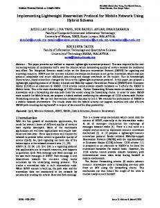
3.2 Fully-overlapped MAF (Greedy) This scheme uses a greedy algorithm and has a potential speedup of a factor of 2. We consider what it takes to fully overlap the two critical paths. First, only the RS - Add path in FADD can be completely overlapped with the PR - Add path in FMPY. The Add - LS path has to be delayed, giving rise to a PR/ES/RS - Add - LS configuration. Second, to merge the RS - Add and the PR - Add paths, we must have provision to shift c either to the right or to the left before S and C arrive. The first case is needed when Ec < Eaxb and the second when E, 2 EaXb. Alternatively, one can add 53 (the number of bits in the significand) to E, so that c will always be right shifted during alignment, as in the IBM RS/SOOO implementation. This implementation, however, requires a triple-width shifter (i.e., 159 bits). Finally, addition occurs only once in this configuration. This means that addition must also perform rounding. To round for the IEEE standard, we now need to examine the lower-order bits of S, C, and c and have to compute additional possible outcomes (i.e., the range of T is larger). Moreover, when c is left shifted to align with S and C, the carry point is now a function of the shift distance and is no longer known in advance. Worse, the input into the normalization shifter (in the LS step) is now also a function of the shift distance. 5 For these reasons, it is not possible to combine rounding with the addition step. This forces us to add an additional rounding step, R, after the LS step, resulting in a configuration that is similar to the RS6000 one: PR/ES/RS - Add - LS - R (Fig. 3~). Figure 4 shows a possible implementation of this greedy strategy. In this implementation, E, has been incremented by 53 so that c only needs to be right shifted for alignment. A 106b shifter is used for this purpose. When the shift distance is greater than 106 bits, the bits need to be accumulated for computing a rounding information. The shifted c is then added to the higher-order 53 bits of S and C in the CSAs. For subtraction, c or S and C must be complemented appropriately according to the effective operation. During the subtraction step, the LOP unit determines the amount of left shift needed for normalization. The higher-order 53b of the result is then rounded. Even with an explicit rounding step, rounding for the IEEE standard is still not trivial in this implement ation. One must compute three pieces of information: First, the 106b right shifter must compute a rounding information from c as mentioned above. Second, the sticky bit logic must sum up the lower-order 53 bits of S and C. Finally, a third piece of 5The RS/SOOO implementation has a similar problem when the shift distance is less than 53 bits.
6
b
a
53x53 Wallace Tree
i 1066 Adder
Sticky Bit Logic
Figure 4: A possible implementation of the SNAP MAF
rounding information is needed from the lower-order bits of the output from the left shifter. These rounding informations must then be combined appropriately for the IEEE rounding modes. From Fig. 4, the MAF latency equation for this Greedy implementation can be written
T.~A&reedy
= TPR + TCSA + TlOsbAop + TlosbLs + TR + Trnc
t
TM~Z t %(Greedy)
(5)
where TlMbJOp is the delay of a 106b LOP. TR is again the latency of the rounding logic and Tlnc is the delay of incrementing the 53b result. TM~~ is needed because the incremented result may overflow, requiring a lb right shift. Tw(Greedy) plays the same role as Tw(FADD) and Tw(FMPY)* These delays can also be thought of as modeling the wire complexity of an implementation. Greedy has a simpler adder datapath than FADD, but it has more wires because of the larger datapath. Hence, we have the following relationship: Tw(Gwedy) - %(FADD) t Tw(FMPY)
The FADD latency of the Greedy implementation is the same as its MAF latency. Hence, we have:
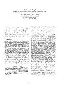
3.3 Partially-overlapped MAF (SNAP) In this scheme, the operations in FMPY and FADD are partially overlapped, giving rise to a PRIES - (Add)/RS - LSJAdd configuration (Fig. 3d). In this configuration, only the Add step in the Add - LS path are combined. Figure 5 shows a possible implementation. In this implementation, we need two 53b shifters for shifting S and C. During FADD, these shifters are used to shift the operands c and d; d is ignored during MAF. The shifters share the same logic for computing the sticky bit. This is accomplished by creating a rounding mask, which is then AND’ed with the lower-order bits of the outputs from the shifters. This rounding mask is also used to produce a rounding constant of the correct weight. The operation of this implementation essentially follows that of FADD except that rounding is now much more complicated. Writing an MAF latency equation for SNAP is slightly more complicated. Because the shift-add path needs the rounding result from the multiplier side, the MAF latency for SNAP is
T.iifAFs~~p =
TPR
t TCSA t T53b4dd t TR t
TGsA(4-2)
t T5364dd t TR t ~TMT.L~ t T,(sNAp)
models the wire delay or its complexity. The RS step is hidden in the addition step in the multiplier side (i.e., the first T5sbAdd) and is therefore not in the equation. The 4-2 CSAs reduce S, C, c, and the rounding mask into two terms, which are then summed up by a compound adder. Typically, where
Tw(SNAP) a g ain
m
Tw(SNAP) > %(Greedy)
8
d
c
a
b
53x53 Wallace Tree S&C
1
I
S3b
S w Shifrer
C 11
53b
4-2 CSA I
53b MUX + (axb)+l-c , c+l-d
Figure 5: A possible implementation of SNAP multiply-add-fused.
Again using the shift-add path as the critical path, the FADD latency can be written as T-FADDSNAP = TES -k T53bR.S i- TcSA(~-2) i- TR -k ~~~~~ i-
T,(sNAP)
(8)
TES is now exposed because the PR step is no longer performed. Only TcsA(d-2) is in the equation because TCSA in the multiplier side is not in this critical path. In the following section, we consider all possible combinations of Eaxb and E, and show that it is possible to round for the IEEE standard in all cases. 3.3.1
IEEE-Compatibility of Partially-overlapped MAF
We have to examine the cases listed in Table 1:
Table 1: Possible cases for IEEE rounding Case 1 2 3 4 5 6
Conditions Effective Addition and Eaxb > E, Effective Addition and Eaxb 5 E, Effective Subtraction and Eaxb - E, 5 Effective Subtraction and Eaxb - E, > Effective Subtraction and E, - Eaxb 5 Effective Subtraction and E, - E,.b >
2 2 2 2
In the table, the exponent difference differentiating the two paths is now 2, as opposed to 1 in the FADD algorithm described earlier. This is because the summation of S and C may overflow. l
l
Case 1: When EaXb > E,, we have to right shift c for alignment. S and C are added in the multiplier side while c is being shifted. In essence, multiplication is performed and rounded independent of the addition step. The MAF instruction allows the FP unit to examine E, in advance and takes action accordingly. After c is shifted, it is then added to the result from the multiplier side. Rounding in this case is similar to that for a multiplier because there are only two shifting possibilities during alignment: right shift and no right shift. Case 2: When Eaxb 2 E,, S and C have to be right shifted for alignment. As pointed out before, the two 53b shifters actually span 106b, preserving the lower-order bits of S and C. On the multiplier side, S and C are added and rounded as usual. The rounding constant from the multiplier side T&ful is now known. This rounding information is passed on to the rounding logic in the adder side. Based on the shift distance, this rounding logic creates a rounding mask, which consists of a string of ‘1’ followed by a string of ‘0’. The transition point determines the location of the carry point. This mask is needed to compute a rounding constant Todd of the proper weight for the adder side because S and C are now shifted. Tjj,fzLl determines the number of masks 10
to be applied. This aggregate rounding mask, S, C, and c are then added using a row of 4-2 adders. Rounding in this case defaults to the first case and is therefore not a problem. l
l
l
l
Case 3: When EdXb - E, _< 2, c needs to be shifted by at most 2 bits. This is just a simple 3-l muxing step. The shifted result is then passed on to the CSAs in the multiplier side. Since c is at most shifted by 2 bits, rounding is not a problem becansca these two bits can be examined and and action taken accordingly. Case 4: When Eaxb - E, > 2, both S and C have to be shifted by at least 3 bits. This case is only slightly more complicated than case 2 because we now have to complement S and C. Case 5: When E, - Eaxb 5 2, S and C have to shifted by at most 2 bit. This muxing step happens at the CSAs in the multiplier side. Rounding in this case presents a problem because S and C are not added and we therefore don’t know if there is to be an overflow to determine TM~[. This information must be computed using a carry-lookahead tree. Case 6: When E, - Eaxb > 2, both S and C have to be shifted. This case is only slightly more complicated than Case 1 because we now have to account for complementation. But as far as rounding is concerned, it can be treated as Case 1.
An interesting question is how many outcomes do we have to compute in each path for correct rounding? In the path that S and C have to be shifted (by at least 3 bits), the rounding mask can at most contribute a constant of 3 x 0.0625. This is because T Mui can at most be 3 and S and C are right shifted by at least three bits. The sum of S and C ranges [0,2). Thus, the range of the fraction is [0,2.1875). The integer portion of 2.1875 will overflow into the result and plays no part in rounding. In the round-to-infinity modes, the fraction 0.1875 causes a rounding ‘1’to be added when the result does not need a right shift during normalization or a rounding ‘2” when it does. Hence, we need to to compute up to five outcomes: S + C + (0,4). The compound adder in this path must be of 51 bits. In other words, the carry point must be at this bit position. In the other path where c has to be shifted by at most 2 bits, the sum of S and C again ranges [0,2). c contributes up to 0.75 (i.e., both LSBs of c are 1). The range is therefore [0,2.75). Again, this requires 5 outcomes to be computed and a compound adder of 51 bits. The compound adder need not compute the 5 outcomes simultaneously. T, determined by a rounding logic, is added to S and C in the CSA step. The compound adder only computes the two results: S + C + T + (0,l).
4 Latency and Hardware Comparison 4.1
Delay Assumptions and Latency Comparison
Table 2 lists the latencies of the major components in the above implementations. These latencies are based on estimates and actual simulation. All latencies are normalized with 11
complex gate implements 3 maxterms with at most 3 literals. The adder uses a conditional sum algorithm for the local sum logic and a modified Ling scheme for propagating the global carry [14]. An X-bit left or right shifter takes the same time as an adder of the same length. TxbJop is roughly ten percent slower than TxbAdd. ES computes the absolute difference of the exponents and is essentially an llb subtraction step, which has a delay of 0.6T. TCSA takes 0.2T because it has two XOR gate delays, which is roughly equal to a complex gate delay in the adder. TcsA(~-2) reduces 4 inputs into 2 with a hidden carry-in and a hidden carry-out. Its gate delay is slightly larger than TcSA). TR is the delay of the rounding logics, which are assumed to be the same for all implementations.6 The latency of an adder increases logarithmically with size, allowing one to compute its rate of increase. But since we are mainly interested in adders of sizes 53b, 106b, and 159b, there is a simpler way. Because a 53b adder has a delay of 5 complex gates and a 106b one has a delay of 6, a 106b adder has a 20% larger latency. Similarly, a 159b adder has a delay of 7 complex gates, therefore TisgbAdd = I .4TssbAdd.
Table 2: Delay Assumptions for CMOS Implementations I Item 53b add 53b right /left shift 53b leading-one prediction 53b increment llb exponent subtraction 53b mux selection 3-2 carry-save add 4-2 carry-save add Round logic 53x53b partial product reduction
Notation T53b4dd T53bR/LS &uop TITlC TES TMUZ TCSA TCSA(4- 2) TR TPR
Delay
T T l.lT
0.8T 0.6T 0.2T 0.2T 0.3T 0.2T 2.OT
Applying the delay information, TFMPY in Eqn (1) is: TFMPY
=
(2 + O-2+ 1-t f-t0.2)Tt Tw(~~py)
= 3*6T + T~(FMPY)
and TFADD
=
(0.6 t 1 t 0.2 t 1 t 2 t 2 X 0.2)T + T+TADD)
= 3.4T + Tw(FADD) Note that since Tw(FADD) > TW(FMPY), TFADD = Tp~py. Table 3 lists the latencies of the MAC, Greedy, and SNAP implementations obtained from Eqns (3)-(8). The latencies for the IBM RS/SOOO implementation are computed using the following latency equations:
“This assumption is likely to place an unfair advantage for the Greedy implementation.
12
T-~AFRS/6000 = TPR + TCSA + &9bLOP
t %9bw,cs + T~i-%xc t Tn/lzLz f Tw(RS/mOO)
and T.FADDRS/~Oo = T-~AFRS/6000
The following observations on Table 3 are interesting. First, MAC has the smallest FADD latency; hence, for applications which have a high percentage of stand-alone FADDs, MAC is not a bad strategy. Second, SNAP has the smallest MAF latency and is the implementation to be preferred if latency is the main concern. Third, the MAF latencies of RS/6000 and Greedy are only slightly better than MAC, but their FADD latencies are considerably worse. Finally, Greedy is faster than RS/6000. The former is IEEE compatible but the latter has higher internal data precision, which requires wider and therefore slower datapaths. In short, we have: T.MAFsNA~ < T.h!fAFG,,,d, < T.MAFMAc < T.MAFRs/~OO
(9)
and T.FADDMAc < T.FADDsNAP < T.FADDGreedy < T.FADDRs,~~~o
(10)
Table 3: Comparison of latency of the three MAF implementations 1 Design
4.2
1
Item
1
Latency
I
Area Assumptions and Hardware Comparison
For comparison, the hardware cost of each component has been listed in Table 4. The cost is based on estimates and on actual layouts in a 3-metal CMOS technology. All implementations are assumed to be static. All costs are normalized with respect to that of a 53b compound adder. Since most high-speed adders use a conditional sum algorithm, a compound adder doesn’t use significantly more hardware than a regular one. Hence, we assumed that &abxLA = &abAdd = A. The area of a shifter is slightly more complicated to determine because an X-bit shifter could mean either its maximum shifting distance is 13
X bits or the shifter actually spans X bits. 7 The latency of a shifter is determined by its maximum shifting distance while its area is determined by its span and to a lesser extent by its shifting distance. In the SNAP implementation, for example, both right shifters shift a 53b input by at most 53 bits. But the shifters have to keep the bits that are shifted out for rounding, spanning therefore 106 bits. Thus, its latency is Ts3ba/LS but its area is A106bl$‘LS. s imi 1 ar remarks hold true for the right shifter in the IBM RS/SOOO implementation; the input of the shifter has 53 bits, but the shifter has to shift a maximum of 160 bits. A~op is the area of an LOP circuit and AxbJop = AxbAdd. We assumed that the area of an adder increases linearly with its size. This assumption is reasonable for the sizes of the adders used in this study.
Table 4: Area Assumptions for CMOS Implementations 1 Notation
1 Item
Area1
A A 0.5A 0.5A
Table 5: Total hardware costs in the three MAF schemes Type
Wallace tree Right shifter Left shifter ComAdd (FADD) ComAdd (FMPY) LOP CLA (round)
T
Unit
Greedy MAC 1 Size(b) Unit Size(b) 53 x 53 1 53 x 53 53 1 106 1 106 53 0 Shared 53 53 1 106 53 1 106 53 2 53
T
SNAP Unit Size(b) 53 x 53 106 53 53 Shared 53 53
R! Unit
6000 Size(b) 53 159 159 159 shared 159 53
Table 5 lists the hardware components in each implementation. The “Unit” columns indicate the number of components used; a zero entry in this column means that the component is shared between FADD and FMPY. In ail implementations, a CLA adder is needed to sum up the lower-order 53 bits of S and C for rounding.8 The FADD of MAC requires two compound adders because of the two-path arrangement. Greedy requires a 106b right 71t could also mean the size of the input to be shifted. ‘Though there are implementations which do not require CLA adders [8, 151, we ignored such a possibility in this study.
14
shifter and a 106b left shifter. The logic in the right shifter needed to compute the sticky bit is ignored, as is the case with other implementations. From Tables 4 and 5, the hardware costs of the implementations are computed and listed in Table 6, where A w, playing a similar role as the T,‘s, represents the area occupied by wires. From the table, we have the following relationship: AMAC < AGreedy < &NAP < ARS/~XOO
(11)
Table 6: Hardware cost comparison of the three MAF implementations 1
Design
txz-
I
Hardware Cost
1 1 APR +
Greedy I 1 SNAP I I RS/6000 I
5.5A
+f%.uiFADD) + AwfFMPY) I
APR
t 7A t &(SNAP\
APR + 7A t A,,,(c=,,,~,,\
APR
t8.5At
I I
&,(~s/isooo~
Because of the higher internal data precision, the IBM RS/6000 implementation consumes more hardware than the implementations considered in this paper, with MAC consuming the least. In terms of percentage, however, the hardware increases in all implementations over MAC are likely small because of APR, which dominates the overall hardware consumption. Table 7 summarizes our findings with MAC used as a reference. The symbol plus (+) means increase and minus (-) means decrease. Double pluses (++) means increase significantly and likewise for double minuses (-). From the table, we see that MAC has low FADD time and uses less hardware than Greedy and SNAP. But its MAF time is high. Greedy trades FADD time, hardware, and rounding complexity for low MAF time. Finally, SNAP has low MAF and FADD times at the expense of hardware and design complexity - rounding and wire complexities. When rounding for the IEEE standard is not a goal (so that rounding is no longer a complication), Greedy and RS /SO00 seem a reasonable middle ground for designs intended for applications with a high MAF to FADD ratio. ASNAP > AGreedy because Aw(SNAP) > Aw(Greedy)-
Table 7: Advantages and disadvantages of the implementations Design TMAF T.FADD Hardware cost Wire Complexity Rounding Complexity = = = = = MAC z Greedy t t t t t La SNAP t t t t t
15
5 Limitations This study has several limitations. First, we assumed a particular implementation for FMPY and FADD. This limitation is not as sever as one might think because the FADD and FMPY algorithms used in this study can be shown to have a minimum number of operations. Second, we used latency and hardware cost as the performance metrics. Another important metric not considered in this paper is the throughput rate. This is to avoid the issue of pipelining, in which, some of the latency in an operation may be hidden in a subsequent operation. In the IBM RS/6000 implementation, for example, rounding is done in the subsequent pipeline stage. A related issue is how to pipeline an implementation effectively. A low latency implementation may be more difficult to pipeline than a higher latency one; this latency advantage therefore may not show up after pipelining. Third, we did not consider the effect of MAF on register and instruction bandwidths and on the complexity of the FP unit controller. We believe, however, that this effect is likely small. Finally, we assumed that the operations in FADD and FMPY are atomic. A finer-grain overlapping strategy may produce a better result. It might be possible to design a partial product reduction hardware that can shift and multiply at the same time. Future studies should address these two open questions: (1) how much hardware increase does an MAF instruction justify? and (2) what MAF (IEEE or RS/6000) - if at all - is better?
6 Summary and Conclusions Multiply-add-fused (MAF) p rovides a viable way to increase the performance of an floatingpoint (FP) unit. The IBM RS/6000 implementation started with different assumptions on the critical paths of an FP multiplier and an FP adder, resulting in a design that is suboptimal in MAF latency. In this paper, we first presented a high-speed FP multiplier and an FP adder designs. We then investigated three possible strategies to overlap the operations in these FP units: (a) non-overlapped, (b) fully-overlapped, and (c) partially overlapped. The first strategy corresponds to multiply-add-chained (MAC) used in vector processors. The second (Greedy) strategy uses a greedy algorithm, yielding an implementation similar to the IBM RS/SOOO one. The third and final (SNAP) strategy uses a less aggressive starting configuration. We showed that (1) MAC has the lowest FADD latency and consumes the least area; but its MAF latency is the highest. (2) Greedy has an intermediate MAF latency but the highest FADD latency. And (3) SNAP provides the lowest MAF latency at the expense of a small increase in FADD latency over MAC and in area over Greedy (Eqns (9)-( 11)). Both Greedy and SNAP have higher design complexity arising from rounding for the IEEE standard. SNAP has an additional wire complexity, which Greedy does not have because of its simpler datapath. This additional wire complexity manifests itself mainly in the form of higher area consumption and increased design complexity. If rounding for the IEEE standard is not a requirement, the Greedy strategy - and the RS/SOOO - seems a reasonable middle ground for applications with high MAF to FADD ratio. 16
7 Acknowledgement The authors wish to thank Dennis Brezenski of HP for the many fruitful discussions on the implementation of multiply-add-fused.
References [l] ANSI/IEEE Standard No. 754, American National Standrads Institute, Washington, DC, An American National Standard: IEEE Standard for Binary Floating-Point krithmetic, 1988. [2] R. K. Montoye, E. Hokenk, and S. L. Runyon, “Design of the IBM RISC System/6000 Floating-Point Execution Unit ,” IBM Journal of Res. and Dev., vol. 34, no. 1, pp. 5970, Jan. 1990. [3] P. W. Markstein, “Computation of Elementary Functions on the IBM RS/6000 Processor ,” IBM Journal of Res. and Dev., vol. 34, no. 1, pp. 111-119, Jan. 1990. [4] C.S. Wallace, “A Suggestion for Fast Multipliers,” IEEE Transactions on Electronic Computers, no. EC-13, pp. 14-17, Feb. 1964. [5] R. De Mori and R. Cardin, “Design for a Recursive Parallel Multiplier,” in Proc. of the 7th Symposium on Computer Arithmetic, pp. 44-50, 1985. [S] D. Zuras and W. H. McAllister, “Balanced Delay Trees and Combinatorial Division in VLSI,” IEEE Journal of Solid-State Circuit, vol. SC-21, no. 5, pp. 814-819, Oct. 1986. [7] Z.-J. Mou and F. Jutand, “A Class of Close-to-Minimum Adder Trees Allowing Regular and Compact Layout,” in Proc. of International Conference on Computer Design, pp. 251-254, 1990. [8] M. R. Santoro, G. Bewick, and M. A. Horowitz, “Rounding Algorithms for IEEE Multipliers,” Proc. of the 9 th Symposium 0 n Computer Arithmetic, pp. 176-183, 1989. [9] N. T. Qua+ N. Takagi, and M. J. Flynn, “On Fast IEEE Rounding,” Tech. Rep. CSL-TR-91-459, Stanford University, March 1991. [lo] S. Waser and M. J. Flynn, Introduction to Arithmetic for Digital Systems Designers. New-York: Holts, Rinehart and Winston, 1982. [ll] M. P. Farmwald, On the Design of High Perfromance Digital Arithmetic Units. PhD thesis, Stanford University, Aug. 1981. [12] N. T. Quach and M. J. Flynn, “An Improved Algorithm for High-Speed Floating-Point Addition,” Tech. Rep. CSL-TR-90-442, Stanford University, Aug. 1990. [13] N. T. Quach and M. J. Flynn, “Design, Analysis, and Implementation of the SNAP Floating-Point Adder,” Tech. Rep. In Preparation, Stanford University, 1991. 17
[14] N. T. Quach and M. J. Flynn, “High-Speed Addition in CMOS,” Tech. Rep. CSL-TR90-415, Stanford University, Fab. 1990. [15] N. T. Quach and M. J. Flynn, “Leading One Prediction - Implementation, Generalization, and Application,” Tech. Rep. CSL-TR-91-463, Stanford University, March 1991.
18