A CBR based pure reactive layer for autonomous robot navigation C. Urdiales, E.J. P´erez and F. Sandoval Dpto. Tecnolog´ıa Electr´onica, ETS Telecomunicaci´on Universidad de M´alaga Email:
[email protected] ABSTRACT This paper presents a new reactive layer using Case-Based Reasoning (CBR) for a hybrid navigation architecture already including a deliberative layer that performs all global planning. Thus, the reactive layer only relies on immediate information about sensors readings, robot heading and relative position to the goal. The proposed layer allows efficient navigation in cluttered environments without significant oscillations. It can easily be trained to deal with hard situations like navigating between two close obstacles. The layer has been succesfully tested in real environments. KEY WORDS reactive navigation, autonomous robot, case-based reasoning
1 Introduction Autonomous robotic navigation consists of finding and tracking a safe path from a departure point to a goal. This problem has been widely studied during the last decades and its solutions range from high-level planning methods to reactive control strategies. High level planning methods require extensive world knowledge so the robot can act in a predictable efficient way. These methods typically rely in a classical sense − model − plan − act cycle known as horizontal decomposition [7]. Deliberative schemes are often criticized for their inability to react rapidly. Also, they strongly depend on a world model. Thus, they are not efficient in partially or totally unknown environments nor in dynamic ones. Alternatively, reactive control methods rely on directly coupling sensors and actuators [3]. Combinations of reactive behaviours produce emergent actions. Reactive schemes are fast and they can easily deal with several sensors and goals. Besides, they are flexible and quite robust against sensor errors and noise. Unfortunately, emerging behaviours may be very unpredictable and, in some cases, non-efficient. Reactive systems are also prone to fall into local traps. Hybrid systems combine deliberative and reactive schemes to achieve a better performance. Low level control is performed in a reactive way whereas high level processing follows a deliberative pattern [1]. Hybrid systems are supported by biological evidence and they can achieve efficient navigation in dynamic and totally or partially unknown environments. The authors proposed a layered hybrid navigation architecture in [15]. The main novelty of this architec-
J. V´azquez-Salceda and M. S`anchez-Marr`e Dpt. de Llenguatges i Sistemes Inform`atics Universitat Polit`ecnica de Catalunya email:
[email protected] ture was a deliberative layer based on a new topologicalgeometrical representation of the environment that provided a set of partial goals to reach a destination point in an efficient way. It included a reactive layer based on potential fields [16] to safely move the robot between partial goals. The deliberative layer granted that the path between two consecutive partial goals would be free of obstacles and could be tracked with mimimum curvature variations as long as the available representation was valid and no unexpected changes occurred. Otherwise, potential fields provided a way to avoid collisions. The main advantage of the architecture regarding its reactive layer is that this layer does not require any knowledge about the global layout of the environment because all high level planning is performed by the deliberative layer. However, potential fields present some drawbacks (see next section). The most important one in our architecture is that they can not be finetuned. Hence, this paper presents a new Case-Based Reasoning (CBR [8]) based pure reactive layer to replace the one in [15]. Section 2 presents an introduction to reactive navigation techniques and CBR based navigation techniques. The new reactive layer is presented in section 3. Section 4 presents some experiments in real environments using a Pioneer robot yielding 8 Polaroid sonar sensors at -90, -50, -30, -10, 10, 30, 50 and 90 degrees respectively. Finally, conclusions and future works are presented in section 5.
2 Previous works Reactive systems tend to directly couple sensors and actuators to decompose overall actions by behaviors rather than by a deliberative process [1]. Overall system behavior emerges from the interactions that take place between the individual behaviors, sensor readings and the world. The potential fields method is probably one of the most popular ones for reactive navigation both in dynamic and static environments [16]. This method consists of creating an artificial repulsion field around obstacles in the environment plus an attraction field around the goal so that the robot moves towards that goal and away from the obstacles. Despite their simplicity and efficiency, potential fields also present some drawbacks. First, it is difficult to move between close obstacles (i.e. doors). They also tend to present oscillations when the robot is close to obstacles. Besides, they may converge to local minima. Some of these problems have already been solved. However, poten-
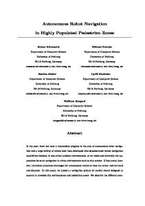
Figure 1. Case definition
tial fields do not act differently in situations where the robot must avoid an imminent collision and in those where it is necessary to navigate close to obstacles. Thus, sometimes they can not move safely through packed areas. Some nonpurely reactive approaches based in a world model have also been proposed. The Vector Field Histogram [14] represents the obstacle density in the environment by means of a local histogram depending on the robot direction so that the robot can move in the direction where there are less obstacles. The Elastic Bands method [12] modifies the trajectory of the robot by using artificial forces depending on the layout of the obstacles in the way. The Dynamic Window Approach [5] models the robot dynamics and the environment into a goal function which is maximized to extract moving commands. The main drawback of all these approaches is that they depend on many parameters that are difficult to optimize for all cases. In this paper we propose a pure reactive layer based on Case-Based Reasoning (CBR). CBR is a learning and adaption technique that helps to solve current problems by retrieving and adapting past experiences, which are stored in the casebase in the form of cases. A case consists of a description of a problem, the solution to that problem and the outcome of problem solving. Basically, using a CBR based reactive layer we can teach the robot how to operate in different situations instead of providing a single analytical solution to all problems. The advantage of CBR compared to black-box techniques such as neural networks is that cases in the database are explicitly stored. Hence, we can have a clear idea of what the robot has learnt and why it comes to one or another conclusion. CBR has been used in navigation before, usually for global path planning in static environments [4] [2]. There are also approaches for global planning in dynamic environments based on a topological map of an a-priori known environment [6]. However, in [6] new opportunities can not be discovered when the environment changes unless the topological map is reorganized regularly. Kruusmaa [9] proposes a grid based CBR global path planning method to overcome the aforementioned problem. However, she concludes that CBR-based global navigation is beneficial when obstacles are large and dense and only few solution exists.
Otherwise, the solution space may become too large. Other CBR based methods focus on reactive navigation [10] [13]. Since they are meant to operate without higher level control, they basically rely on accumulating experience over a time window while navigating in a given environment to obtain an emergent global goal seeking behaviour. The novelty of our approach is that our CBR-based layer is meant to be integrated into the hybrid architecture in [15]. It does not require any knowledge about a particular environment because it is simply meant to efficiently avoid unexpected obstacles in the way by modulating the path calculated by a deliberative layer. Thus, it is valid for any environment. The deliberative layer also prevents the reactive layer from falling into local minima.
3 A CBR based reactive layer 3.1 Case definition A case can be regarded as a vector in an N-dimensional space. When a potentially interesting situation is detected, a CBR cycle consists of four steps: i) retrieve the most similar stored case; ii) adapt its solution to the current case; iii) evaluate the results; iv) learn from the new experience. In order to define a case, it is necessary to define which attributes conform the vector, how solutions can be adapted and how results are evaluated. A pure reactive layer is basically defined by the sensor readings and the goal. If no deliberative layer is available, either a time sequence of sensor readings [13] or a explicit model of the environment [9] is required. In our case, we simply operate with the current readings of 8 on-board Polaroid sonar sensors. Sonars can detect obstacles as far as 6-8 meters away. However, they also present a wide uncertainty arc. Thus, far obstacles can not be precisely located unless statistical techniques are used to combine information in time and space. We achieve some space integration by evaluating the readings of all 8 sensors. We also provide some time integration by pondering negatively sharp trajectory changes in our evaluation function. Besides, in our case, far obstacles are not important because the deliberative layer provides a global way of avoiding them to reach the goal. We only react to close obstacles, which are either unexpected, moving or, simply, close to the robot path. The case library we use is organised as a flat structure. This kind of structure makes easier to test and try several strategies to tune the CBR system to obtain the best results. However, in a near future, other kind of formalisms can be studied. In this type of case library structure, the retrieval step relies on a nearest neighbour algorithm (k-NN) to obtain the most similar case to the local situation of the robot to be used in the next adaption step. Similarity assessment is a key point in the process of finding out the best case to be adapted. There are some measures commonly used in the CBR field such as Euclidean distance, Manhattan distance, normalised measures, heterogeneous measures or probabilistic measures. In some preliminary
robot-goal vector and the advance direction, so that the robot do not move very far from its goal point. Also, in order not to get too close to obstacles, the smallest sonar reading is also included in the evaluation. Fig. 1 shows how a case is defined for a robot equipped with 5 sensors. The attributes of the case are the readings of the 5 sensors plus the goal direction (long grey arrow). The evaluated factors are the shortest distance to obstacle dmin, the curvature variation α1 and the angle between the resulting heading direction (short grey arrow) and the goal direction α2.
3.2 Training stage
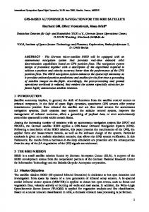
Figure 2. Training stage
work [11] it has been empirically proven that L’Eixample measure outperforms the accuracy of most measures if the attribute relevance is well defined, either by domain experts or by automatic feature weighting techniques. For this reason, it has been adopted in the experimental evaluation of our approach. The performance of this measure is good because it exploits the domain knowledge about attribute relevance in order to compute similarities in a more accurate way, combining discrete and continuous attributes in CBR applications. We have empirically tested that small differences in sonar readings are not too significant to characterise a given situation. Thus, we discretize those readings into 5 intervals: i) critical (0-20 cm); ii) near (20-50 cm); iii) medium(50-100 cm); iv) far (100-150 cm); and v) no influence (150-800 cm). It must be noted that the first three intervals are smaller because the robot needs to be specially cautious when obstacles are so close. It is also important to note that these values are only valid for a typical indoor environment. As aforementioned, we also need to include the goal in the case attributes. Since we do not use a model of the environment, we can not represent the goal by means of coordinates. Instead, we represent it by means of a vector joining our current position to the goal. The current implementation works only with the direction of the vector. Using all this information, the system must return the direction that the robot must follow to safely reach the goal given its current situation. Since the proposed scheme is a purely reactive one, solutions can not be evaluated in a global way. Thus, the solution to a single case can not be judged good or bad in terms of reaching the goal. Instead, we use three simple local criteria. In order to provide some temporal inertia against sonar noise and to prevent slippage as much as possible, we evaluate curvature changes in the robot trajectory. Hence, the robot tends not to change its direction abruptly. The second evaluation factor is the angle between the
Before the robot starts to operate on its own, we have performed a supervised trained stage to adquire a basic case base. This stage basically consisted of manually guiding the robot towards a goal blocked by a single obstacle. The robot was freely guided by three different persons through two different routes, leaving the obstacle on the right and on the left of the robot. Fig. 2 shows the learning environment. The departure and arrival points are marked with white tape. Two examples of possible training trajectories are marked with discontinuous lines. A new case is included in the data base each time a significant sensor configuration is detected. We consider that a given sensor configuration is significant when its distance to the previously stored one is larger than a fixed threshold. Our goal was to ultimately let the robot choose the best chain of cases to reach a goal by combining different guides and routes. It must be noted that the robot does not learn complete routes, but adequate actions for a given sensor configuration. It can be observed that the robot basically stores immediate solutions to immediate problems. No solution on its own is enough to reach the goal. During this learning stage, the robot made 6 different routes and stored 160 cases. It must be noted that we explicitly avoided adquiring information in cluttered environments to test how flexible the system is against unexpected situations.
3.3 Adaptation stage The adaptation step is a domain-dependent process, so it has to be designed accordingly for each domain. Some strategies have been tested, mainly based in mathematical adjustments through interpolation techniques between the most similar case and the current one. However, if the distance between those cases is too large, the solution can not be correctly adapted. We have detected that critical problems usually occur when obstacles are significantly closer to the robot in the problem at hand than in the stored case. In these cases, the robot usually collides with obstacles. To avoid this, those situations are easily detected by comparing the shortest distance to obstacle in the stored case dmin (Fig. 1) with the current shortest distance to obstacle. In those detected cases, we substract the direction of the sonar detecting this shortest distance from the hea-
ding suggested by the stored case. The resulting heading plus the rest of the case parameters in those particular situations are stored in the case base as a new case. Thus, if no similar case is available and an obstacle is near in a given situation, the robot corrects its heading to move away from the obstacle. When the learning stage is finished, the robot can operate on its own. When a goal is set, the robot changes its heading to reach it in a straight way. If no obstacles are within the reactive layer perception range, the robot tries to change its curvature as little as possible. In the best case, it follows a straight line. Otherwise, the reactive layer is triggered. Then, the most similar learnt situation is extracted from the case base and the trajectory of the robot is changed to avoid collisions. It must be noted that the reactive layer changes the deliberative trajectory not only when there is an obstacle in the way but also when there are obtacles close to the path. Each time the robot changes its trajectory, new cases may appear and the reactive layer can be retriggered. Thus, the final emerging trajectory to reach the goal is a composition of several discrete cases that are not necessarily related to a single training trajectory. This emergent behaviour is a combination of the best cases previously learnt according to the current chain of events.
Figure 3. Test with two separated obstacles
4 Experimental results After the six routes in the learning stage were learnt (section 3.2), we performed a set of tests in a laboratory. Since this paper focuses on the reactive layer, we disabled the deliberative layer in our architecture. Thus, the robot always tried to reach a goal in a direct way. When no obstacles were found in the reactive range, the robot arrived to the goal by following a straight path. Since the laboratory is not a large environment, we set the reactive range to a radius of 0.5 meters around the robot to consider only critical and near obstacles because walls were at medium range. Obstacles farther than 0.5 m. did not trigger the reactive layer. Nevertheless, when the layer is triggered all detected obstacles have influence in the resulting solution.
4.1 Emergent behaviours In situations with a single obstacle, where there were only small variations from the learning stage layout, the robot easily reached the goal in a smooth way. Thus, we performed some experiments where two obstacles were put in the environment. First, these obstacles were separated enough to allow the robot to perceive them sequentially and not at the same time. Fig. 3 shows one of these tests. The trajectory is extracted from the robot odometry. However, since no map was constructed, the position of the obstacles overimposed to the trajectory is not exact. Thus, we also include a picture of the experiment layout for a better understanding of the problem. Initially, the robot is aligned with the x axis and turns 13 degrees left to head the goal.
At the beginning, the closest obstacle is approximately 1 m. away. Thus, the reactive layer is not triggered until the obstacle on the left is detected ”near” by sensor 3 at 30 degrees. The reactive layer recalls that driver 2 faced a a similar case in his route 1 and suggests to turn right. It can be observed that there is no sharp curvature change. However, this turn makes sensor 2 detect the obstacle as well at 50 degrees. The closest case in the case base is related to obstacles not closer than 1.2 m (”far”) (driver 3, route 2). Hence, the output heading direction is corrected and the robot turns left to move away from the closest obstacle. In this case, the turn can be clearly detected because curvature is not preserved when these corrections are made. This change puts the robot out of the area of influence of the right obstacle. Thus, the robot tries to gain the goal in a straight way once more until the obstacle on the left is perceived again at 43.9 cm (”near”). The reactive layer suggests to turn slightly right until the robot is out of the area of influence of the left obstacle as well (driver 2, route 1). Finally, when the robot is out of the area of influence of the obstacles, it turns right again to reach the goal in a straight way. It can be observed that the emergent behaviour of the robot is mainly based on the first route of driver 2, where the robot moved on the right of a single obstacle. To test how the robot behaves when obstacles are detected at both sides at the same time, we forced it to move in a straight line between two obstacles and learn 40 extra cases. Potential fields tend to fail in these cases, so we compared their performance with the proposed reactive layer. Fig. 4 shows one of these tests. We put both obstacles
Figure 4. Test with two close obstacles
Figure 5. Test with three obstacles
closer and closer until potential fields failed and a collision was detected (continuous line). Then, we ran the same test using our reactive layer and keeping the same obstacle layout (discontinuous line). Basically, the robot moved in a straight line until both obstacles were detected with sonars 1 and 5 at 39.3 (”near”) and 53.1 cm (”medium”) respectively. The reactive layer had a similar case stored and recommended a very soft turn left (3 degrees) (driver 2, route 1) that can barely be appreciated in Fig. 4. The potential fields, though, made the robot move away from the closest obstacle on the left and into the one on the right. Of course, potential fields can be adjusted so that the robot does not get so close to the obstacles to minimize the risk of collisions. However, in such a case the robot would not have moved between both obstacles. Extracting cases from the last trained route, our reactive layer kept telling the robot to follow a straight line until the narrowest area between both obstacles was reached. In this case, obstacles are at 20.8 (”near”) and 19.2 cm (”critical”) respectively. Then, the reactive layer suggested to turn softly to the right. It must be noted that curvature tends to be preserved and hence these inflection points are not very noticeable. Finally, we also ran some tests were three obstacles were randomly set in the environment. Fig. 5 shows one of these tests. In this case, it can be observed that the potential fields also converge to a correct solution (continuous line). However, in cluttered areas potential fields oscillate more than the proposed layer (discontinuous line). In this case, the robot moves ahead to the goal until the reactive layer is triggered by a ”near” obstacle on the left. In the clo-
sest case in the base, obstacles were in the ”no influence” area. Hence, the ”turn left” order is corrected into a ”turn right one”. However, in this case no sharp curvature variation appears. The robot moves even nearer to the obstacle and further corrections are required. When the robot detects the left and right obstacles at 27.7 cm and 46 cm respectively, the ”corridor mode” is recalled and the reactive layer makes the robot move in parallel with the left obstacle. When the right obstacle gets significantly farther than the left one, the reactive layer returns to its favorite ”driver 2 route 1” routine to leave the obstacle on the left. However, it soon detects the final obstacle in the front at ”near” range. No similar situation is available and the case returned is corrected to avoid the obstacle on the right. In this case, the correction provokes a sharp curvature change. From this point on, the reactive layer combines the routes proposed by drivers 1 and 2 to leave an obstacle on the right until obstacles are out of the detection range and the robot can safely reach the goal.
5 Conclusions This paper has presented a new CBR based pure reactive layer for autonomous navigation. The layer does not require global knowledge about the environment. Instead, it only learns how to deal with unexpected situations both in a supervised and unsupervised way. The proposed reactive layer may fall in local traps but, since it is meant to operate with a deliberative one, the system can efficiently
solve such a problem. The main advantages of the proposed layer are: i) it can be supervisedly trained to solve difficult situations; ii) training a few significant paths in simple environments is enough to unsupervisedly operate in more complex ones in an efficient way; and iii) it provides paths between close obstacles and does not oscillate much in cluttered areas. The main drawbacks of the proposed layer are that: i) the adaptation stage is still very simple and new cases are only adquired when obstacles are very close; ii) when a new case is learnt, curvature is not necessarily preserved; iii) since the layer input only relies on instant sonar readings, the system is sensitive to repeated multiple echoes. Further work will focus on improving the adaptation stage, filtering multiple echoes, including a non supervised training stage and integrating the layer with our hybrid architecture.
6 Acknowledgements This work has been partially supported by the Spanish Ministerio de Ciencia y Tecnolog´ıa (MCYT) and FEDER funds, project TIC2001-1758.
References [1] R.C. Arkin, Behaviour based robotics, MIT Press, Cambridge, 1998 [2] L.K. Branting and D.W. Aha, Stratified case-based reasoning: Reusing hierarchical problem solving episodes, Proc. of the 14th Int. Joint Conf. on Artificial Intelligence, Montreal, Canada, 1995 [3] R.A. Brooks, Intelligence Without Reason, Proceedings IJCAI-91’, pp. 569-595, Sydney, Australia, 1991. [4] S. Fox and D.B. Leake, Combining case-based planning and introspective reasoning, Proc. of the 6th Midwest Artificial Intelligence and Cognitive Science Society Conference, Carbondale, IL, 1995 [5] D. Fox, W. Burgard and S. Thrun, The Dynamic Window Approach to Collision Avoidance, IEEE Robotics & Automation Magazine, 4(1), 1997 [6] K.Z. Haigh, and M. Veloso, Route planning by analogy Proc. of Int. Conf. on Case-Based Reasoning, Springer Verlag: Berlin, pp. 160-180, 1995 [7] H. Hu and M. Brady, A parallel processing architecture for sensor based control of intelligent mobile robots, Robotics and autonomous systems, 17, pp. 235257, 1996 [8] J. Kolodner, Case-Based Reasoning. Morgan Kaufmann, 1993
[9] M. Kruusmaa, Global navigation in dynamic environments using Case-Based Reasoning, Autonomous Robots, 14, pp. 71-91, 2003 [10] M. Likhachev and R.C. Arkin, Spatio-temporal casebased reasoning for behavioral selection, Proc. of the IEEE Int. Conf. on Robotics and Automation (ICRA), Seoul, Korea, pp. 1627-1634, 2001 [11] H. N´un˜ ez, M. S`anchez-Marr`e and U. Cort´es, Similarity measures in Instance-Based Reasoning, Submitted to Artificial Intelligence, 2003 [12] S. Quinlan and O. Khatib, Elastic Bands: Connecting Path Planning and Control, Proc. of the IEEE International Conference on Robotics and Automation (ICRA), pp. 802-807, Atlanta, USA, 1993 [13] A. Ram and J.C. Santamaria, A multistrategy casebased and reinforcement learning approach to selfimproving reactive control systems for autonomous robotic navigation, Proc. of the 2nd Int. Workshop on Multistrategy Learning, Harpers Ferry, West Virginia, 1993 [14] I. Ulrich and J. Borenstein, VFH: Local Obstacle Avoidance with Look-Ahead Verification, Proceedings of the IEEE International Conference on Robotics and Automation (ICRA), pp. 2505-2511, San Francisco, CA, 2000 [15] C. Urdiales, A. Bandera, E.J. Prez, A. Poncela and F. Sandoval, Hierarchical planning in a mobile robot for map learning and navigation, in Autonomous Robotic Systems - Soft Computing and Hard Computing Methodologies and Applications, D. Maravall, D. Ruan and C. Zhou (eds), Physica Verlag, pp. 165-188, 2003 [16] J.S. Zelek, Dynamic issues for mobile robot real-time discovery and path planning, Proc. of Computational Intelligence in Robotics and Automation (CIRA’99), pp. 232-237, Monterrey, California, 1999