constitute a behavior and for each possible event de- scribe the system's reaction. We employ a nite state machine FSM - with states representing behaviors and ...
Executing Reactive Behavior for Autonomous Navigation (Extended Abstract) Benny Rochwerger
Claude L. Fennema� Bruce Draper Edward M. Riseman
Allen R. Hanson
Computer Vision Laboratory Dept. of Computer Science University of Massachusetts Amherst, MA 01003
Abstract Complex problems, such as driving, can be solved more easily by decomposing them into smaller subproblems, solving each sub-problem, and then integrating the solutions. In the case of an autonomous vehicle, the integrated system should be able to \react" in real time to a changing environment and to \reason" about ways to achieve its goals. This paper describes the approach taken on the UMass Mobile Perception Laboratory (MPL) to integrate independent processes (each solving a particular aspect of the navigation problem) into a fully capable autonomous vehicle.
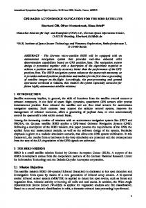
1 Introduction One of the goals of the autonomous vehicle e�ort at the University of Massachusetts is the development of a landmark-based navigation system capable of robust navigation both on-road and cross-country. The experimental laboratory vehicle for this e�ort is the Mobile Perception Lab (MPL) - a heavily modi ed Army HMMWV ambulance that is equipped with actuators and encoders for the throttle, steering and brake and passive sensors (Figure 1). The task of autonomous navigation, as with many other complex tasks, can be decomposed into more speci c subproblems like road following, obstacle avoidance and landmark recognition. In order to achieve a fully autonomous vehicle, the solutions to all these subproblems must be integrated into a coherent system. Since each of the subproblems is still a eld � Computer Science Program, Mount Holyoke College - South
Hadley, 01075 MA
Figure 1: The Mobile Perception Laboratory, built on a modi ed HMMWV chassis, has computer controlled steering, throttle, and brakes, a complete research laboratory on the back.
of active research, in which approaches and solutions may change rapidly over time, it is important to provide an environment in which researchers can quickly experiment with di�erent combinations and parameterizations of those modules. At the same time, MPL's software environment must be e�cient enough to meet the demands of real-time navigation. This paper focuses on the preliminary work done on the problem of integration for the MPL.
Wait [ vs, tl, ~rf ] Green
Red
Drive [ rf, tl, dm ]
Done
Stop [ vs, ~rf, ~tl ]
2 What is a behavior? In the robotics literature, the word behavior has generally been used to describe processes that connect perception to action, i.e., a behavior senses the environment and does something based on what was perceived. A combination of behaviors is also called a behavior, thus, a complex behavior can be achieved by combining simpler behaviors. In Brooks' subsumption architecture [3], the task of robot control is decomposed into levels of competence; each level, in combination with lower levels, de nes a behavior. Payton, Rosenblatt and Keirsey [6] in their Distributed Architecture for Mobile Navigation system (DAMN), refer to behaviors as very low level decision-making processes which are guided by high level plans and combined through arbitration. In their DEDS work, Ramadge and Wonham [8], events are considered the alphabet, �, of a formal language; a behavior is a sequence of events, or a string over �� . Note that in this terminology every pre x of a string is also a behavior, i.e., the sequential combination of behaviors is a behavior. These de nitions, although consistent, can be confusing - the same term is used for individual processes and for the composition of these processes. To make the distinction clear, we have chosen to think of a behavior as a mode of operation [6], in which several perception-action processes [9] are executed concurrently. Each process converts sensory data into some kind of action (either physical or cognitive), and at any time may generate an event - a signal to let the system know that \something" signi cant has occurred. All inter-process communication is achieved through a global blackboard - a section of shared memory accessible to all1 . The system reacts to events by changing its behavior; hence the sequence of behaviors actually executed depends upon the sequence of events. Since the latter is unpredictable, so is the former. To proIn its current incarnation, the blackboard is built on top of the ISR3 - a symbolic real-time database for vision [2]. 1
Figure 2: Script of a simple driving system: (a) Finite state machine (FSM) representation. Listed below the state name are the perception-action processes that should be run and killed (marked with a ~ ) in that state. This example is composed of four perceptionaction processes: follow the road (rf ), check for tra�c lights (tl ), monitor the distance traveled (dm ), and stop the vehicle (vs ). gram such a system, one must specify which processes constitute a behavior and for each possible event describe the system's reaction. We employ a nite state machine (FSM) - with states representing behaviors and transitions representing reactions to events - to specify the system. For example, consider the FSM in Figure 2. This system will drive on the road while obeying tra�c lights, until a given distance is travelled. Based on the notion of behaviors represented as states of a nite state machines, we have implemented a Behavior Description Language (BDL) [9]. Behaviors are described as two sets of perception-action processes, and a transition table. The run set speci es the minimum set of processes that form the behavior; the kill set speci es those processes that should not be running for the correct execution of the behavior. The transition table speci es what to do for each of the valid events (events not speci ed in the state description are not valid).
3 Scripts - Augmented nite state machines In our model tasks are given to the system in terms of nite state machines. As the complexity of the vehicle's task grows, this approach may lead to long and repetitive representations (the
drive-100-meters state would probably ilar to the drive-150-meters state).
be very simTo alleviate this problem, the FSM is augmented with a fetch-goal state, and the states are parameterized. A particular behavior (like drive for 100 meters or drive for 150 meters) is instantiated from this generic description through the use of blackboard messages at run time. The system starts in the fetch-goal state where it reads goals (in terms of states) from a precompiled plan. When a goal is retrieved, the relevant blackboard messages are written into the blackboard before enabling the perception-action processes. Once such a process is running, it looks for its parameters in the blackboard. Formally, a script S is de ned as the eight-tuple (P; Q; E; M; �; �; �; G), where: � P is the set of available perception-action processes. � Q is the set of states (Q = B [ fetch-goal, where B is the set of behaviors). � E is the set of possible discrete events (transitions in the FSM). � M is the set of valid blackboard messages. � � is the transition table, � : B � E ! Q � � is the kill table, � : B � P ! f0; 1g � � is the run table, � : B � P ! f0; 1g � G is the plan expressed in terms of subgoals. Each subgoal is of the form < bg ; Mg >, for bg 2 B and Mg � M . Scripts can be generated by an automated planner, or by hand (using BDL).
3.1 The script monitor The script monitor in our system is in charge of \high level" control2 : reading, interpreting, and executing BDL scripts. The monitor does not perform any action on the vehicle, instead it controls the set of running processes at any time. The script monitor consists of two modules, an interpreter and an executer. The interpreter takes a BDL script S and builds the transition (� ), kill (�) and run (�) tables; then the subgoals in S 's plan are stacked into the execution stack G. The executer simulates a nite state machine as follows:
2 In this context, \high level" control is used to di�erentiate the control of processes from the \low level" control of the vehicle actuators.
1. bg fetch-goal 2. if (bg = fetch-goal ) then (a) if G is empty then 8p 2 P i. kill(p) ii. if (�(bg ; p) = 1) then run(p) iii. stop (b) < bg ; Mg > pop(G) (c) blackboard Mg 3. 8p 2 P if (�(bg ; p) = 1) then kill(p) 4. 8p 2 P if (�(bg ; p) = 1) then run(p) 5. Wait for an event e 2 E 6. bg � (bg ; e) 7. goto 2 Clearly, for the system to complete the task in G, the following must hold:
8b 2 Q 9sb 2 E +
^(
s:t: � b; sb
) = f etch , goal
where �^ is the transition function applied to a sequence of events.
4 An example The following perception-action processes have been successfully tested on the MPL:
� Vehicle pose determination based on landmark � � � � � �
model matching [1, 5]. Neural-network road following (ALVINN) [7]. Servo-based steering [4]. Obstacle detection via stereo. Re exive obstacle avoidance. A distance monitor. Turning via dead reckoning.
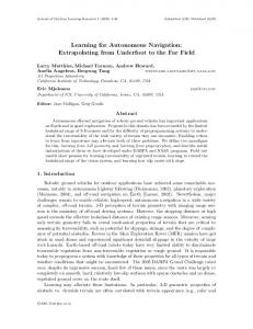
Theses processes were combined in a script to achieve the following: 1. Drive on the road, while avoiding obstacles, for x meters.
table, instead it executes \scripts" which eventually will be written by an automated planner.
success
success
drive−onroad [ rf, od, dm ]
ob
st
compute−pose [pe, ~rf, ~se]
ac
ar cle
le
obstacle fetch−goal [ vs, ~ALL ]
drive−off road [ se, od, dm ]
avoid−obstacles [oa, od, ~rf, ~se]
Acknowledgements This research was supported by DARPA via TACOM under contract number DAAE07-91-C-R035 and by the National Science Foundation under grant number CDA-8922572.
clear
success turn [ dt, dm ]
success
Figure 3: An augmented FSM for on/o� road navigation : drive while avoiding obstacles for a speci ed distance, then check position. The perception-action processes involved include pose estimation (pe ), road following (rf ), obstacle detection (od ), obstacle avoidance (oa ), servoing (se ), distance monitor (dm ) and dead reckoning turning (dt ). 2. Estimate vehicle position using landmarks. 3. Drive on the road, while avoiding obstacles, for y meters. 4. Estimate vehicle position using landmarks. 5. Turn left (at the experimental site this command is a transition to o�-road navigation). 6. Drive o� road, while avoiding obstacles, for z meters.
5 Conclusions An autonomous vehicle should be able to react in real-time to a changing environment, but it should also be able to reason about its goals. In our system, these seemingly contradictory capabilities are achieved through the use of a\programable" nite state machine. In this model, reactions to events (either internal or external) are represented as state transitions. The system can react rapidly by following a transition table. Goal-directed reasoning is supported by the \programability" of the FSM - the system does not enforce what goes into a state or a particular transition
References [1] R. Beveridge. Local search algorithms for geometric object recognition: Optimal correspondence and pose. Ph.D. Thesis CMPSCI TR93-71, University of Massachusetts at Amherst, 1993. [2] J. Brolio et al. The ISR: an intermediatelevel database for computer vision. Computer, 22(12):22{30, 1989. [3] R. A. Brooks. A robust layered control system for a mobile robot. IEEE Journal of Robotics and Automation, RA-2(1), March 1986. [4] C. L. Fennema. Interweaving reason, action and perception. Ph.D. Thesis COINS TR91-56, University of Massachusetts, 1991. [5] R. Kumar. Model dependent inference of 3D information from a sequence of 2D images. Ph.D. Thesis COINS TR92-04, University of Massachusetts at Amherst, 1992. [6] D. W. Payton, K. Rosenblatt, and D. M. Keirsey. Plan guided reaction. IEEE Transactions on Systems, Man and Cybernetics, pages 1370{1382, 1990. [7] D. A. Pomerleau. Neural network based autonomous navigation. In Charles Thorpe, editor, Vision and Navigation: The CMU Navlab. Kluwer Academic Publishers, 1990. [8] P. J. Ramadge and W. M. Wonham. The control of discrete event systems. Proceedings of the IEEE, 77(1):81{98, January 1989. 1994. [9] B. Rochwerger et al. Executing reactive behavior for autonomous navigation. Technical Report CMPSCI TR94-05, University of Massachusetts at Amherst, 1994.