A class of authentication digital watermarks for secure multimedia
Recommend Documents
Different copies of a document containing digital fingerprints differ at most at these .... For each sample point, a list of hyperplane indices will be issued. .... x1, x2, x3...xn) with redundancy r1, e.g. vr1=3=(x01, x01, x03, x11, x12, x13,....,xn
authenticity in the traditional printed medium is the watermark, which has begun to be ... The distribution of free product samples is the gravity for snowballing success. .... simply add the keystream itself into the host data, then later detect its
traditional digital signatures may be used for complete ... Content Authentication (MCA). ... sections where a digital signature can be placed. Because multimedia ...
document or a printed ticket to fool the system without triggering alarm to ... of a ticket. In the following, we discuss the seven basic properties required for off-line.
selected serves as the authentication signal symbol, and for each cl a mapping to a .... To accomplish this, a digital signature is embedded as the watermark.
access to the unused space between Digital Television. (DTV) channels, or the white ..... To accomplish this, a digital signature is embedded as the watermark.
Farzad Safaei. University of Wollongong, [email protected]. Research Online is the open access institutional repository for the. University of Wollongong.
INTRODUCTION. A digital watermark provides a communication channel multi- ...... in information and telecommunication en
Mar 8, 2012 - back-end server sends a message using the updated identi- ...... UCLA, in Wireless Internet for the Mobile Enterprise Consortium (WINMEC), ...
Mar 8, 2012 - back-end server sends a message using the updated identi- ...... UCLA, in Wireless Internet for the Mobile Enterprise Consortium (WINMEC), ...
embedding watermarks, signatures, and captions in digital data. A watermark ... termarking is an application which embeds a small amount of data, but requires ...
As a result, research communities are increasingly seeking tools that enable them to collaboratively analyse and annotate such multimedia content, either.
documents on the internet and the administration can check ... permits to check document authenticity. .... Checking the user digital signature: this consists.
Java application running on any internet machine. Communication with server is also secured via a symmetric encryption: RC4 [7]. 6. The encoded signature of ...
Nov 7, 2004 - a provably secure authentication mechanism for digital multimedia ... invertible fragile watermarks to embed a digital signature of the media.
Internet banking might be the prime example; with it comes the added challenge of .... In contrast to one-time codes, authentication based on public-key cryptography .... protected client PC by means of a virus or a Trojan horse (see Figure 2c).
so low quality, that there is a need to add the visibility of the watermark, in order to get the phone to ..... (online) [viitattu 29.1.2007] Saatavilla pdf-muodossa: ...
Department of Electronics & Communication Engineering. National Institute of ..... Associate Engineer at Renesas Mobile Corporation, Bagalore, India. His.
Many market research reports indicate that the demand for various ... delivery of multimedia content over open and generally insecure networks, e.g., the ... communication overhead, receiver buffer size, delay, and tolerance to packet losses.
Another approach is to apply a transcoder at some node of the multimedia delivery .... Encryption and digital signature generation in a DRM system, on the other ...
In image authentication watermarking, hidden data is inserted into an image to
detect ... Authentication Watermarking – Binary Images – Pattern. Matching –
Shuffling. ..... in Binary Image for. Authentication and Annotation”, IEEE
Transactions.
your own website. You may ..... PAAA transmits AU T HG1 and the own identification. IDP AAA to .... and successfully set up the conversation key between vessel.
As weil, it is wise to start iterating at a number of different initiai values and then average ...... [2] Kathleen T. Alligood, Tim D. Sauer, James A. Yorke. Chaos: an ...
Nov 16, 2006 - Secure authentication watermarking for localization against the HollimanâMemon attack. Niladri B. Puhan · Anthony T. S. Ho. Published online: ...
A class of authentication digital watermarks for secure multimedia
tation or shifting, and image enhancement by histogram equal- ization and sharping, etc., are ... the fundamental concepts of the watermarking are presented,.
1754
IEEE TRANSACTIONS ON IMAGE PROCESSING, VOL. 10, NO. 11, NOVEMBER 2001
A Class of Authentication Digital Watermarks for Secure Multimedia Communication Liehua Xie and Gonzalo R. Arce, Fellow, IEEE
Abstract—A new approach to digital signatures for imaging, which adapts well to multimedia communications in lossy channels is introduced. Rather than attaching the signature’s bit-string as a file-header, it is invisibly etched into the image using a new watermarking algorithm. The watermark is “nonfragile,” tolerating small distortions but not malicious tampering aimed at modifying the image’s content. In particular, the rank-order relationship in local areas throughout the lowest level of the DWT is exploited to encode the watermark. An edge-based message digest is used. The signature is in the form of binary data and the wavelet decomposition coefficients are modified according to this binary sequence. The signature is also embedded and tested within the SPIHT compression algorithm. The information capacity is studied and the experimental results confirm a logarithm relation between the bit rate and the quantization level, which is similar to the Shannon’s capacity theorem. Experiments are performed to examine the signature’s transparencey and robustness.
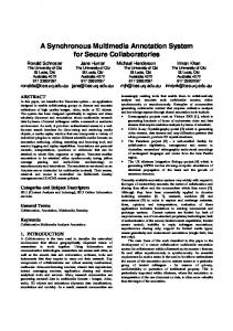
Fig. 1. Traditional DS sender: signing with private key.
Index Terms—Bit capacity, content based image authentication, nonfragile digital signature, wavelet compression domain watermark.
I. INTRODUCTION
D
IGITAL signatures (DS) are electronic protocols used for the authentication of electronic documents whereby a receiver of a message can verify the identity of the sender and the integrity of the message [1]. With the advent of multimedia communications over the Internet, it is natural, and critical in many applications, to provide security mechanisms in the transmission of imagery data. To this end, the need of digital image signatures emerges for applications where the security, integrity, and authenticity of images are important. Military and forensic imaging are two such areas where the security features of digital signatures are desirable. Digital signatures do not simply encrypt the entire message with a secret key—although direct cryptography does provides security, it can be a prohibitively computationally expensive approach particularly with large multimedia data sets [2]. Instead, digital signatures encrypt a message digest which is in essence a “fingerprint” of the electronic file. Message digests, such as Manuscript received October 25, 1999; revised July 28, 2001. This work was supported in part by the National Science Foundation under Grant CDA9703088, by Dupont, and through collaborative participation in the Advanced Telecommunications and Information Distribution Research Program (ATIRP) Consortium sponsored by the U.S. Army Research Laboratory under the Federated Laboratory Program, Cooperative Agreement DAAL01-96-2-0002. The associate editor coordinating the review of this manuscript and approving it for publication was Dr. Naohisa Ohta. The authors are with the Department of Electrical and Computer Engineering, University of Delaware, Newark, DE 19716 USA (e-mail: [email protected]; [email protected]). Publisher Item Identifier S 1057-7149(01)09362-9.
Fig. 2.
Traditional DS authentication receiver: verification with public key.
Rivest’s MD5 [3], generate a compact digest of the message using cryptographic one-way hash functions of the message [2]. The message digest represents the message such that even if one bit of the original message is changed, a different message digest would be obtained from the modified message. In addition, it is computationally infeasible for an attacker to device a substitute message that would produce an identical message digest. The crypted message digest is attached to the document and subsequently jointly transmitted or stored. The receiver recovers the original message digest from the digital signature by decrypting it with the sender’s public key. He then computes a new message digest from the received message, and if it matches with the one recovered from the digital signature, the receiver is confident that the message was not altered, and that it came from the sender who owns the public key used to check the signature. The generation of a traditional digital signature at the transmitter, and the authentication process carried out at the receiver are illustrated in Figs. 1 and 2.
XIE AND ARCE: CLASS OF AUTHENTICATION DIGITAL WATERMARKS
Although traditional digital signatures can be used with image data where the raw or compressed image files are treated as data files, it will be apparent shortly that traditional digital signatures are neither efficient nor adequate in many lossy communication environments. Consider the case of layered image coding, as an example, where “low-priority” image bits can be dropped during transmission due to network congestion, introducing small or negligible distortion in the image reconstruction at the receiver. In the likely event of “low-priority” bit loss during transmission, a conventional digital signature, would fail the authentication protocol in this example since the received image data and the signed data are not identical. This drawback is even more serious in broadcast and internet multicast applications where lossy channels are the norm. In this paper, we develop a new approach to create digital signatures for imaging that adapts well to applications in multimedia communications. Rather than attaching the signature’s bit-string as a header to the image file, we invisibly etch the digital signature into the image data using watermarking methods. In general, the watermarked signature is still public key encrypted for added security if needed. Embedded in the image data, the encrypted signature cannot be removed by file conversions or simple image manipulations. Furthermore, the digital signature is not “fragile” in that it tolerates small or negligible distortions caused by compression or other standard manipulations performed in multimedia communications. It does not, however, tolerate other malicious tampering that modifies the content of the image by the addition or removal of objects. II. ETCHING SIGNATURES IN THE WAVELET DOMAIN A. Desirable Etching Characteristics We start with the underlying assumption that compression is inevitably used during transmission. Assuming the contrary is not practical in most applications. Moreover, if compression is assumed, no compression is included as a special case in the assumed framework. We also assume that the communication is lossy where bit errors can occur due to noise or as a consequence of congestion in multiplexed networks. Thus, it is possible that the transmitted and received image data are not identical. These assumptions indicate that the etching of digital signatures must be robust to lossy compression and that the authentication mechanisms must not be “fragile,” tolerating minor distortions on the data. The former requirement suggests that the watermarking and compression algorithms used for secure transmission should be coupled in some way in order to attain higher efficiency. The latter requirement suggests that the signature must record “strong” rather than “weak” image features. The use of conventional message digests, such as MD5, are not appropriate in this case as they are “hard” one-way hashing functions disallowing authentication even if a single bit of the data is modified. Note we consider image compression as an acceptable image transformation in the communication channel. Other manipulations such as geometrical attacks by image rotation or shifting, and image enhancement by histogram equalization and sharping, etc., are taken as image tampering because such manipulations are not normal in image transmission. In this
1755
Fig. 3. Watermark engraving structure. The median of a nonoverlapping running window b is modified according to the watermark bit x. Figure depicts the case when b b .
=
paper, we mainly study the impact of image compression on the watermarks. The watermarking of digital signatures must also be blind where the authentication process at the receiver end can be carried out without any knowledge of the original image being transmitted [4]. In order to implement a blind decoder, the watermarking process etching the digital signature must introduce memory by relating several image coefficients with the etching of a single watermark bit rather than encoding the watermark bit into only one coefficient. This concept is analogous to sequence modulation in communication channels [5]. Finally, the watermarking algorithm for etching digital signatures should be invisible to the naked eye. B. Watermarking a Wavelet Transformed Image As suggested above, higher efficiency can be attained if the watermarking and compression algorithms are jointly considered. In this paper, we focus on compression algorithms which are based on wavelet decompositions. The extension of the algorithms proposed here to other compression approaches, such as JPEG, is straight-forward. First, a “soft” message digest of the image is generated which only captures the “strong” image features [6]. More on the generation of “soft” message digest will be said later on. It suffices to say at this point that traditional cryptographic message digests are not adequate. Thus given the bit-sequence of a “soft” message digest, the goal is to etch it into the wavelet decomposed image representation. At first, for ease of explanation, we present the watermarking algorithm in the wavelet domain without compression. Once the fundamental concepts of the watermarking are presented, the watermarking algorithm is then integrated within a zero-tree type wavelet compression algorithm [7], namely the SPIHT codec [8]. To assure robustness, the bit sequence of the message digest will be etched into the low-frequency band of the wavelet image representation. The etching algorithm is illustrated in Fig. 3 and is described next. We slide a nonoverlapping running window through the entire low frequency band of the wavelet decomposed image. Assume a 3 1 window is used although other window shapes can be used as well. Elements within the window are denoted as , , , which are the coefficients’ value at locations with coor, , . Given the coefficients , dinates , , we denote the corresponding rank-ordered coefficients . We then perform a nonlinear transformaas tion algorithm, changing the median of these coefficients while
1756
IEEE TRANSACTIONS ON IMAGE PROCESSING, VOL. 10, NO. 11, NOVEMBER 2001
keeping the remaining coefficients the same. A detailed description of this operation will be presented at the end of this section. , which is obtained by the Denote the modified median by transformation, (1) where is the watermark bit sample to be etched in the location of the window and is a user defined tuning parameter. At the receiver, watermark extraction is an inverted etching process. The decoder needs only to know the value of , the watermark length, and the necessary key if the watermarks are encrypted. A rectangular window of the same size as the one used in watermark engraving is applied to the received image. , and is obtained as A sequence with elements: the window is shifted. We can get two possible values of if if
Fig. 4. Two possible median samples, b to the watermark. k is assumed odd.
, being adjusted to b
according
The boundary of the partitions are denoted as , , with being with . Define the the smallest integer for which as , then the median is region in the interval as transformed into case case where
(2)
where possible value of watermark sample; ; . and the two possible We compare the distance between in (2). is then selected as the one which makes values of closest to . Thus, the watermarked bit associated with the window at each location is extracted as (3) Shifting the decoding window throughout the entire watermarked image, we obtain the entire embedded watermark sequence. C. Rank-Order Based Transformation Here, we introduce the nonlinear transformation in (1) which is employed in the signature engraving scheme. A rank-order manipulation is motivated due to the concern of edge preservation [9], [10]. Edge properties determine the local coefficients’ rank order, therefore, the rank-order must be preserved as well. Basically, the transformation changes the median of a local area to a value set by its neighbors. Given the coefficients , , and the corresponding order statistics , , , the scaled midpoint is first defined as the spacing parameter (4) where is a tuning parameter with its default value of 0.05. is adaptive to the overall local coefficients’ magnitude so that the strength of the watermark is varied according to the local characteristics of the coefficients in the observation window. Next, , ) is partitioned into inthe range of the coefficients ( , tervals, each interval of length . Note that if we consider the local area to be too smooth to contain a watermark and the set of coefficients are skipped. Thus, a watermarked local area must satisfy (5)
case
is odd and
case
is even and
or or
is even and is odd and
where is the bit of the watermark being inserted in the location of the window. For example, if the bit of the watermark to be lies in , etched at a particular window location is 0, and if . If the watermark bit is 1, and , then then . In Fig. 4, for instance, is assumed odd. By adjusting , we are able to tune the strength of the watermarks. and is proportional with , Since is larger and when increases, the range of the change on will generate artifacts on the image. too much change on On the contrary, when decreases, image quality will be more likely preserved. However, the watermark is more vulnerable to noises because it is weaker. Therefore, there is a tradeoff for between the watermark’s robustness and transparency. The proposed scheme is able to engrave the signature data into a large number of images while preserving their image quality. Figs. 5 and 6, for instance, depict an original 288 500 . image and its corresponding watermarked image with The test image is chosen because it contains distinct objects that can be effectively used to illustrate image tampering. The peak signal to noise ratio (PSNR) is 38. Fig. 7 depicts a watermarked image where the tuning parameter is made too large and the watermarked image quality is degraded. Fig. 8 visually shows the artifacts introduced as is increased. The lower left section of the image represents the error between the original in in Fig. 7. The Fig. 5 and the watermarked image with top right section is the error between the original and the waterin Fig. 7. The blocking artifacts on marked image with the latter case are clearly seen. III. WATERMARKING WITHIN A WAVELET COMPRESSION FRAMEWORK The need to implement the watermark algorithm within a compression algorithm arises when compression is used during transmission. The signature engraving must be embedded within the particular compression scheme adopted by the protocol. Here, we adopt the SPIHT compression algorithm [8].
XIE AND ARCE: CLASS OF AUTHENTICATION DIGITAL WATERMARKS
Fig. 5.
Fig. 6. Watermarked image with
Original image.
= 0:05 and two-level DWT decomposition.
A. SPIHT Algorithm In essence, the SPIHT algorithm aims to keep large coefficients (quantized) and throw away small coefficients in the DWT transform domain. It uses a tree-structured indexing in order to exploit the pyramid decomposition. In particular, the concept of parent–child dependencies is used. A coefficient at a coarse scale is referred to as a parent and all coefficients at the next finer scales at the same spatial location and of similar orientation are referred to as the children. Furthermore, the coefficients at all finer scales on the same spatial location and of similar orientation are called the descendents of that coefficient. The brothers of a coefficient are those coefficients having the as same parent. We denote the coefficient at coordinate and define
1757
Fig. 7. Watermarked image with = 0:5 and two-level decomposition.
Fig. 8. Upper right part: the difference between the original image and the image in Fig. 7. Lower left part: the difference between the original image and the image in Fig. 6.
virtual brothers at level 0 and they are enclosed in the dark dotted line square. Next, we examine those features in the SPIHT algorithm relevant to our application. The algorithm implements a progressive transmission method by using the binary representation of the magnitude-ordered coefficients. The coefficients are ordered by magnitude and the most significant bits are transmitted first. Furthermore, subset partitioning using the spatial tree structure is employed to expedite the search for the significant coeffiand all of its descendents are an excients. In Fig. 10, node is considered ample of a partitioned subset. A coefficient significant if it satisfies
The descendents of The brothers of Fig. 9 depicts the hierarchical relationship of the coefficients obtained by a two-level DWT decomposition of image . The hierarchical tree structure of the coefficients is shown in Fig. 10. is a coefficient in the high frequency component In Fig. 9, , (HH0) at the highest level of a two-level decomposition. , , are the children of and they are brothers to each other. A dark square, which covers a 2 2 area, is used in Fig. 9 to show the brother relationship of those coefficients under the together with are the window. descendents of . For the convenience of implementation, we and its three adjacent coefficients , and as regard
where is the bit level. , where is the highest bit level, and is the last bit level at the end of the coding when the requested compression ratio is met. For notational simplicity, we let . The significance test decides whether the coefficient is to be coded or discarded at the current bit level. is treated as an In the coding algorithm, the brother set indivisible group, which is made up by 2 2 adjacent pixels. are to be tested at the th bit level, Either all members in or the group is discarded. Therefore, at the end of transmission, each member in the group will be represented with the same accuracy. This fact is important in our algorithm since it allows us to conveniently track such a group while at the same time
1758
IEEE TRANSACTIONS ON IMAGE PROCESSING, VOL. 10, NO. 11, NOVEMBER 2001
Fig. 10.
Hierarchical tree structure used by SPIHT coding.
Thus, the lower bound of bined, we get
is determined. When (5) is com(7)
Fig. 9. Two-level DWT decomposition.
the group is made up of coefficients that represent the information of a neighboring area. In our algorithm within the compression framework, rather than sliding a nonoverlapping window throughout the decomposed image, we slide the non overlapgroup yields a ping 2 2 window at locations where the significant coefficient.
C. Multibit Engraving
B. Signature Engraving At the encoder, the SPIHT algorithm is executed first. The output of the SPIHT algorithm generates a hierarchical list of the significant coefficients. To insert the watermark, the 2 2 nonoverlapping window is scanned through all the brother sets where at least three coefficients survive quantization, i.e., those coefficients are significant at the last bit level, the th to debit level. Another test is next performed on each set cide whether or not a watermark bit can be inserted. Since the window is 2 2 at each location and contains four coefficients, , , , , we select three of these coefficients such that these correspond to the ones with the largest absolute value. These three coefficients are then sorted by their actual value yielding , , in ascending order. To the three order-statistic apply the watermarking, we define if otherwise
(6)
indicates if watermark engraving in the local where is admissible. is the last bit level to determine window that satisfy the significance of the coefficient. For those , we proceed with the watermarking process. We calculate the scaling factor .1 At the quantization stage, is quantized into the multiples of the quantization constant , i.e., where the function is the lowest integer truncating “floor” function. Since is meaningless, the minimum of is , i.e., . 1Recall
S
= (( b j
j
+
j
Thus, if a local area is considered significant for watermarking, the image data in the area must contain a margin larger than the compression quantization threshold. Note that the watermarking locations are no longer constrained to be in the top level of the DWT pyramid. The locations are distributed in all bands and are determined by the local characteristic of the underlying image.
b
=2).
j)
In general, the engraved signature is represented by binary data such that one bit at a time is engraved where admissible. The watermark capacity, however, can be increased if we engrave as many bits as we can in each window location. This is in (6) is significantly larger than possible if the range . the threshold Recall that information is hidden in a local area where the co, which efficient range overcomes quantization constant is the minimum quantization threshold used when coding ends. , we perform the watermarking Thus, when into intervals of method by partitioning the range and by modifying according to the watermark length is several times larger than , we sample. However, when into smaller segcan refine the engraving process and split ments. Formerly, we inserted two watermark values only: 0 and 1. Now if the distance is twice as large as that of the quantization constant, a 3-ary symbol (0, 1, or 2) can be inserted. This approach is called “multiple bit engraving.” Fig. 11 depicts the concept behind multibit engraving where the size of partition used in binary engraving is . Two bits of information can be hidden in this case. As we can see, multiple bit engraving is similar in principle to the binary approach. D. Edge Information Message Digest As stated previously, a message digest in the traditional sense does not fit the needs of a “soft” message digest for the image. For example, the MD5 algorithm [3] hardly tolerates any distortions in that it produces a 128-bit message digest using a strict one-way hashing algorithm. Hash algorithms for images have been studied in [11]–[14]. In our approach, the edges of the
XIE AND ARCE: CLASS OF AUTHENTICATION DIGITAL WATERMARKS
1759
Fig. 11. Comparison of binary and multibit engraving methods: (a) binary engraving method and (b) multibit engraving method.
image are used as the content’s fingerprints in order to make the message digest robust to minor artifacts introduced during communication. Usually, the edge detector is applied at the rescaled image with a reduced size, or the lowest frequency component of wavelet decomposition, for the following reasons. First, the number of watermark bits we can embed in an image is not large enough to carry the edge map of the image with the original size. Secondly, the edge map of a lower resolution image will be less sensitive to minor artifacts introduced by compression and simple image manipulations. The size of the edge map is image dependent, however, the decoder must know the length of the watermark sequence to extract the signature. One solution is to set up “rules” agreed by both sides: the sender and the receiver. For example, both sides can adopt a Sobel edge detection on the LL component of a three-level wavelet decomposition. As long as the encoder and decoder use the same edge detector, the edge-based message digest proves reliable. If a change of edge information is detected, the authentication algorithm decides that the image has been tampered. In fact, it is desirable that the message digest is of fixed length for the convenience of authentication. A two level message digest can be generated, where the MD5 algorithm is applied to the edge-based message digest. For added security, the message digest can be encrypted either by a secret key shared by both sides or using a public key encryption [2]. We note that edge maps are not strictly cryptographic hash functions as it is computationally feasible to find another image which provides the same edge map; however, it satisfies our needs to detect gross image changes. A comparison between the edge information carried by the original image (Fig. 5) and the corrupted image (Fig. 12) is shown in Fig. 13. The difference of their edge maps is shown in Fig. 13(c). Fig. 13(d) overlaps the edge difference in dark color and the received image. Furthermore, due to the multiresolution decomposition performed by the wavelet transform, if tampering has occurred, the edgebased message digest is able to roughly point out the place where the tampering took effect by checking the watermark bits embedded at the lowest level of DWT. E. Algorithm Comparison Here we compare our watermarking algorithm with another wavelet-based technique developed by Kundur and Hatzinakos [15]. The two algorithms were developed independently but both etch watermark in the transform domain by dividing the distance between the maximum and the minimum into equal length intervals, associating the boundaries between the intervals with a zero-valued or a one-valued bit alternatively,
Fig. 12.
Tampered image with one building replaced.
Fig. 13. (a) Edge of the original image; (b) the edge of the corrupted image; (c) the difference between (a) and (b); and (d) (c) as seen on the corrupted image. The questionable area is highlighted in the figure.
and adjusting the median to the nearest boundary associated with the same binary bit as the watermark. The difference between the two etching processes lies in how the distance is divided and the choice of transform coefficients. In Kundur and Hatzinakos [15], the distance between the maximum and the minimum is divided into a fixed, user defined . Meanwhile, the watermarks are number of intervals, embedded in different resolutions of the detail images. In our algorithm, the number of intervals is adaptive to the magnitude of the maximum and the minimum and is tunable by . We believe that the adaptive approach will lead to less artifacts and watermark capacity. For watermark etching in the uncoded transform domain, we choose to use the approximate image, the lowest frequency component (LL0) for its robustness. In fact, we tested the use of fixed number of intervals in our algorithm and found objectionable visual artifacts unless is sufficiently large. In Kundur and Hatzinakos [15], the image “Barb” and no visible artifacts was rewas watermarked with is used to etch the ported. However, artifacts are found if watermarks in the LL0 band. Therefore, we believe the image quality is better preserved if the number of intervals is adaptive responding to the values of the local coefficients. We believe that the watermarking and compression algorithms used for secure transmission should be coupled in order
1760
IEEE TRANSACTIONS ON IMAGE PROCESSING, VOL. 10, NO. 11, NOVEMBER 2001
to attain higher efficiency. In Kundur and Hatzinakos [15], the watermarks are carried by the details of image (HL, LH, HH), which are fragile to wavelet compression. Through Sections II and III, we contributed a watermarking method embedded within the SPIHT compression scheme. Further contribution to the information capacity of data hiding is presented in the coming section. IV. INFORMATION BIT RATE The bit rate of a watermark (measured in bits per pixel) indicates the amount of information that can be embedded within an image, which is particularly important for content based signatures since the length of the binary data representing the signature is often large. An overview of the capacity issue in data hiding in images is given in [16]. A. Information Capacity for Multibit Engraving Scheme In this section, we show that the information capacity for multibit engraving scheme is bounded by the rate given by Shannon’s channel capacity theorem, although a different interpretation of noise is used. According to Shannon’s results [17], given the average transmitter power , and assuming having a that the noise is white Gaussian noise of power bandwidth , by sufficiently complicated encoding systems it is possible to transmit binary digits at a rate (8)
bits can be embedded in a selected local area with larger , is upper bounded by . In order to however, b) shows that derive the capacity upper-bound, maximum use of the available margin is assumed, which implies that b) may be ignored at this moment and we examine a) only. To arrive at the information capacity, we exploit the similarity between the proposed signature scheme and signal detection in . a communication channel. a) discloses the lower bound of A watermark bit can only be inserted in a local window where the distance between the maximum and the minimum coefficients is large enough to overcome the quantization. The median in a window is changed by watermarking, and the window is placed in a significant local area where the image data in the local window contains a margin larger than the quantization constant . In other words, we are exploiting the local variance of an image. Because of coefficient truncating, the quantization constant becomes the unit for measurement. The local variance is evaluated using multiples of . Therefore, quantization becomes a critical factor for information embedding. It is clear that whether or not a watermark signal can be engraved , i.e., the distance of is determined by the range of the two signals. The information bit rate we can achieve by our engraving scheme is equal to the maximum rate of signals . The following evolves directly from with noise power Shannon’s theorem. Theorem 4.1: The information bit rate we can engrave in an image is bounded by (9)
where is the channel bit rate. The inequality sets up the upper bound on the possible rate for an error-free communication channel subject to Gaussian noise. The principle Shannon used to derive the upper limit is that two symbols modulated at the sender in a communication channel must have a noise margin in order to get the correct decision at the receiver. With the assumption of white Gaussian noise, Shannon proved that “the probability of a given perturbation depends on the distance from the original signal and not on the direction.” Two signals are distinguishable if their noise region is nonoverlapping since overlapping result confusion at the receiver. Therefore, the capacity problem can be formulated by finding the maximum rate of signals which satisfy 1) the avand 2) the distance erage power is and it is band-limited to between two signal in their geometrical representation is larger than the noise power . In our signal and distortion model, the compressed image is approximated as a continuous, band-limited channel. We regard the compressed image as the signal and the quantization truncation as the source of noise. Let us assume the image , has . How power and the quantization constant is where many bits of information can we embed? As discussed in Section III-B [see (6) and (7)], a local area to be watermarked is selected if it meets the following constraints: ; b) , where the range of , a) , is denoted by , and . During multibit i.e., signature engraving, we change the median in a window to a fixed value set by its neighbors and the watermark bit. More
where information bit rate; image power; ; quantization constant; image’s bandwidth. An intuitive understanding of this result is important. When is very small such that it goes to zero, so does . This result corresponds to images with constant areas having small variance where little information can be etched. On the contrary, when is larger, the capacity is larger. So images with larger variance can hide more information. is taken into account, a factor When b), the constraint on is used to adjust the strength of the watermarks. The effect of on the capacity of the watermarking algorithm is described in the Appendixes and is summarized in Section IV-C. B. Information Capacity for Binary Engraving Scheme Next, we consider the binary engraving case. In the previous section, it was shown that the bit rate is related to the quantization constant. Their relationship is studied as follows. In the coding algorithm, the higher bits of a coefficient are sent first and the coding ends whenever the desired compression ratio is met. It may happen that some of the coefficients have been quan, however, the coding may end before the remaining tized to . Hence, the coefficients sent coefficients are quantized by may be truncated at two different quantization thresholds, and
XIE AND ARCE: CLASS OF AUTHENTICATION DIGITAL WATERMARKS
1761
, because of the incomplete scan of the last bit level. Thus, different quantization thresholds may exist and the fraction of coefficients that are truncated by each threshold vary with different compression ratios. Here, a bit rate corresponding to each quantization constant is defined at some “ideal” compression ratio, with which the quantization threshold is “complete” in the sense that all coefficients are truncated by the same threshold and all are sent. coefficients which are no less than ( to ) is defined to describe the quanA sequence where is an integer usually tization constants. with less than . Since we are only interested in those is the largest quanwhich watermark engraving is possible, tization constant when at least one watermark sample can be inis: 64, 32, 16, 8, 4, 2, 1, and . serted. An example of ( to ) to denote those “ideal” We use a sequence . The bit rate for compression ratios corresponding to each is bounded by the bit rates the compression ratios other than s closest to it. We also define sequence and of the two to be the bit rate with compression using multibit engraving and binary engraving respectively. We derive an approximate relation between the bit rate sequence of multibit and binary engraving. The approximate ca. pacity equivalence is indicated by the symbol Theorem 4.2: The bit rate of binary engraving is related to the bit rate of multiple bit engraving by (10) (11) The proof is attached in Appendix B. Note that the second relation in Theorem 4.2, i.e., (11), can also be obtained from (10) at , i.e., and is far if we assume that . These equations can be used to predict less than and . We can predict if we know , or we can predict if we know . The latter is particularly useful since we . This assumption plus have derived an upper bound for the the other assumptions used in the proof were verified by the experiments, especially in the case of large compression ratios. C. Effect of
on the Capacity
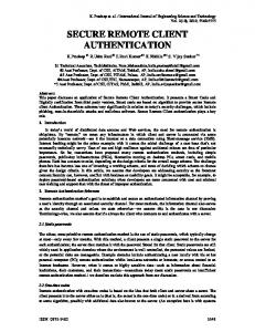
Here, we present experimental results illustrating the information capacity as a function of quantization. Our experimental results confirm a logarithm relation between the bit rate and the quantization level. The results are presented in Figs. 14–16 and Table I. Fig. 14 plots the watermark bit rate for an eight-bit 512 512 image versus . and remain a constant in the plot. The horizontal axis is inversely related to the compression ratio. As increases, the quantization increases, the compression ratio increases, but decreases. The bit rate results include: experimental results using multibit engraving, experimental result using binary engraving scheme and the upper bound. The signal power is estimated by the image’s variance that is measured in the ( ). The spatial domain. Sequence upper bound is obtained by measuring the image’s bandwidth in the FFT transformed domain to approximate the bandwidth [18]. The bandwidth is obtained as the frequency where the power spectrum density (psd) decays 30 db from the DC level. In Fig. 15, we plot the bit rate at various quantization levels vs . The same image is used as in Fig. 14. It is clear that the while . maximum bit rate is attained for In Table I, we depict the experimental results of the number of bits using multibit and binary engraving methods, where stands for the experimental result and stands for the prediction by sequence . Similarly, is the experimental result and the predictions by sequence . The estimation and the experimental data are very close especially when is small where the quantization constant is large. To show the impact imposed , we also calculated the bit rate of by the floor function multibit engraving not using the floor function and obtained the . are the predictions made using . sequence The final experiment performed on the information bit rate was the measurement of the watermark bit rate in bits per pixel and PSNR for images with different sizes. As Fig. 16 shows, the bit rates for the 512 512 image and the 256 256 image are comparable at the same PSNR, especially when the PSNR ). Fig. 16 illustrates the relation between the is low ( SNR and the bit rate. V. EXPERIMENTAL RESULTS
In the Appendixes, the impact of on bit rate by multibit engraving and binary engraving is studied. We find that the bit rate by multiple engraving arrives its maximum when . is an approximate threshold of with which the range is fully exploited for watermarking (see Apof pendix B-1 for the definition of ). At that point, the capacity upper-bound follows Theorem 4.1. In addition, a sequence ( to ) is defined to describe the tuning parameter . and are defined to be the bit rate at a particular compression ratio using multibit engraving and binary engraving, respectively, and a set of equations similar to those in Theorem 4.2 (12) (13) is obtained.
D. Simulations
Under the wavelet compression scheme, several experiments were run to evaluate the robustness of the signature and the image quality change that resulted from the signature engraving. Our experimental results show that the signature achieves our initial goal of robustness and transparency. A. Authentication Under Image Compression The impact of image compression on the watermarks is studied. We repeatedly compressed the image with the signature using different compression ratios and extracted the as the embedded information out each time. Let’s denote compression ratio applied when the signature was engraved. Our experimental results show that the signature stayed in the image if the compression ratio used in later compression was . In the experiment, we compressed lower than or equal to the watermarked image more than ten times and the signature
1762
IEEE TRANSACTIONS ON IMAGE PROCESSING, VOL. 10, NO. 11, NOVEMBER 2001
TABLE I EXPERIMENTAL DATA AND THE PREDICTED CAPACITY USING MULTIBIT AND BINARY ENGRAVING AT 0:125
=
Fig. 14. Relation of bit rate and quantization using binary and multibit engraving at .
was not altered. These experiments show that the signature is more robust if engraved at high compression ratios. Since compression is a low pass filtering process, the result agrees with arguments by Cox [19] that robust watermarks must be put in the most significant components. In all, the experimental results show that the signature embedded at higher compression ratios is more robust than signatures embedded at lower compression ratios. However, it is expected that fewer bits can be engraved when the compression ratio is higher. This is understood since higher compression smoothes the image and reduces the possibilities of data hiding. Therefore, there is a trade-off between the information bit rate and the robustness of the signature. B. Visual Impact of the Signature on an Image “Transparency” refers to the visual impact of the signature on the image. We use the MSE and PSNR to measure the visual impact. A comparison of the MSE and PSNR of the original image versus the compressed image with and without the signature was computed and it is observed that there is little difference brought by signature engraving. Particularly, the difference gets smaller when the compression ratio is higher.
Fig. 15.
Fig. 16.
related bit rate at various quantization level.
Logarithm relation between the information rate and PSNR.
VI. CONCLUSION Digital signatures for secure transmission and distribution of digitized images are becoming important with the rapid development of information technology. In this paper, we propose a content based digital image signature system for image authentication using digital watermarking techniques. We introduce a blind watermarking digital signature for the purpose of authentication. Thus anyone, with access to the embedded public cryptographic keys, wishing to authenticate watermarked images is able to do it, provided the watermarking retrieval mechanism is available. An edge based message digest is developed which is capable of detecting image tampering. The signature survives in a lossy environment provided the signature is robustly embedded. The information capacity was studied. For multibit engraving, the capacity is shown to be bounded by the rate given by Shannon’s channel capacity theorem where the noise is the effective quantization. An approximate relation between the bit rate sequence of multibit and binary engraving was derived. Experimental results illustrate the signature’s robustness and its perceptual visual impact on the image, and confirm the theoretical results in the information bit rate.
XIE AND ARCE: CLASS OF AUTHENTICATION DIGITAL WATERMARKS
1763
since
APPENDIX A PROOF OF THEOREM 4.2 , we index all the significant areas by Proof: At and name them . We also define the sequence [ to ] for each . . Note that must be larger Let . The number of bits we can engrave by the or equal than multibit engraving method is (14)
for those , . Furthermore, we assume that . Using (20), we conclude that is small compared to . If we omit the small term and combine (17) and (21), is simplified to (22)
proving the first result of Theorem 4.2. The proof for the second result in Theorem 4.2 follows a similar development and is not presented here. APPENDIX B EFFECT OF ON THE CAPACITY
is the lowest integer truncating “floor” where the function function. Similarly at A. Impact of (15) And that and follows that
where are the new admitted areas. It can be seen . Define such that so . It is equal to
by Multibit Engraving
In our scheme, the range of split into intervals with the size of
, denoted by
, is
(23) The maximum bit rate corresponds to the multibit engraving is fully exploited. However, is bounded method, by which by (24)
(16) Since
,
is equal to
(17) Let
be the first term on the right side of (17). Denoting and , we have (18)
was made to remove the where the approximation “lowest integer” operation. Using the Taylor expansion on , we obtain (19) where Since
are the higher order terms compared with for those , and , then discarding the higher order terms, we have
.
(20) The second term in (17),
, is (21)
implies that information will not be embedded in a implies no watermarks in a weak very smooth area and area where the multiplication of the tuning parameter ( ) and is less the overall magnitude of the local area than the quantization constant . satisfies (24), when increases, For those locations where increases ( is proportional with ), the bit rate of the watermarks increases since more levels are obtained when a larger is split by at the refining stage (see Fig. 11). Also, by (24), , so there exists such that there is an upper-bound for with which the maximum number of bits can be enin one window graved in the local area. However, will be equal to using the same in does not mean for the entire image at the other windows. We estimate an point that the following approximation holds in average (25) is estimated using the average of over the average i.e., in all local areas. One of the overall magnitude is (an 8 bit 512 512 image example value of , the capacity problem goes back to is tested). When and what we have discussed in Section IV because by is equivalent to splitting by . Therefore, splitting the capacity upper-bound follows Theorem 4.1. is beyond the bound provided For those locations where by (24), there is no watermark. The smaller , the smaller is and there are more locations that , the bit rate will , while . No decrease. When , the bit watermarks will be inserted at places where rate will also decrease.
1764
IEEE TRANSACTIONS ON IMAGE PROCESSING, VOL. 10, NO. 11, NOVEMBER 2001
As a result, the bit rate arrives its maximum when . At that point, the capacity upper-bound follows the logarithm function in (9) with parameters , and variable . and the Bit Rate Of Binary Engraving
B.
( to ) is defined to describe the A sequence and to be the bit rate tuning parameter . Define at a particular compression ratio using multibit engraving and binary engraving respectively. In this paper, a sequence is examined. and . Similar to the proof of Theorem 4.2, we index all the signifby and name them icant areas at . Thus, the number of bits we can engrave by the multibit engraving method is (26) and, (27) . Comparing the above with the two where equations that start the proof of Theorem 4.2
[8] A. Said and W. A. Pearlman, “A new fast and efficient image codec based on set partitioning in hierarchical trees,” IEEE Trans. Circuits Syst. Video Technol., vol. 6, pp. 243–250, Mar. 1996. [9] L. Xie and G. R. Arce, “A blind content based digital image signature,” in Proc. 2nd Annu. Fedlab Symp. Advanced Telecommunications/Information Distribution, vol. 1, College Park, MD, Feb. 1998. , “A blind wavelet based digital signature for image authentica[10] tion,” in Proc. Eur. Signal Image Processing Organization (EUSIPO) Conf., Sept. 1998. [11] J. Fridrich, “Robust bit extraction from images,” in Proc. 1999 IEEE Int. Conf. Multimedia Computing Systems, vol. 2, Florence, Italy, June 1999. , “Visual hash for oblivious watermarking,” Proc. SPIE, vol. 3971, [12] Jan. 2000. [13] G. R. Arce, L. Xie, and R. F. Gravemen, “Approximate image authentication codes,” in Proc. 4th Annu. Fedlab Symp. Advanced Telecommunications/Information Distribution, vol. 1, College Park, MD, Mar. 2000. [14] L. Xie, G. R. Gonzalo, A. Lewis, and B. Basch, “Methods for soft image/video authentication,” in Proc. 4th Annu. Fedlab Symp. Advanced Telecommunications/Information Distribution, vol. 1, College Park, MD, Mar. 2000. [15] D. Kundur and D. Hatzinakos, “Digital watermarking using multiresolution wavelet decomposition,” in Proc. 1998 IEEE Int. Conf. Acoustics, Speech, Signal Processing, vol. 5, Seattle, WA, May 1998. [16] F. A. P. Petitcolas, R. J. Anderson, and M. G. Kuhn, “Information hiding—A survey,” Proc. IEEE, vol. 87, July 1999. [17] C. E. Shannon, “Communication in the presence of noise,” Proc. IRE, vol. 37, Jan. 1949. [18] A. K. Jain, Fundamentals of Digital Image Processing. Englewood Cliffs, NJ: Prentice-Hall, 1989. [19] I. Cox, J. Kilian, T. Leighton, and T. Shamoon, “Secure spread spectrum watermarking for multimedia,” in Proc. 1996 IEEE Int. Conf. Image Processing, vol. 3, Lausanne, Switzerland, Sept. 1996.
(28)
(29) , we find that the settings of the two where problems are almost the same. As it turns out, a similar set of equations (30) (31) can be obtained if we make similar approximations and assume . The proof of it is analogous to the proof of Theorem 4.2. REFERENCES [1] A. Furche and G. Wrightson, Computer Money. Heideberg:dpunkt: Verlag fur Digitale Technologie, 1996. [2] B. Schneider, Applied Cryptography: Protocols, Algorithms, and Source Code. New York: Wiley, 1996. [3] R. L. Rivest, “RFC1321: The md5 message-digest algorithm,” Internet Activities Board, Apr. 1992. [4] S. Craver, N. Memon, B. Yeo, and M. Yeung, “Can invisible watermarks resolve rightful ownerships?,”, IBM Res. Tech. Rep. RC 20509, July 1996. [5] R. E. Blahut, Digital Transmission of Information. Reading, MA: Addison-Wesley, 1990. [6] M. Scheneider and S. Chang, “A robust content based digital signature for image authentications,” in Proc. 1996 IEEE Int. Conf. Acoustics, Speech, Signal Processing, vol. 4, Atlanta, GA, May 1996. [7] J. M. Shapiro, “Embedded image coding using zerotrees of wavelet coefficients,” IEEE Trans. Signal Processing, vol. 41, pp. 3445–3462, Dec. 1993.
Liehua Xie was born in Hunan, China. She received the B.S. degree in electrical engineering from Beijing University, Beijing, China, in 1995, and the M.S. and Ph.D. degree in electrical engineering from the University of Delaware, Newark, in 1998 and 2000, respectively. From September 1996 to June 2000, she was a Research Assistant in the Department of Electrical and Computer Engineering, University of Delaware. She has consulted with industry in the areas of image and video processing. Her research interests include image and video processing, image authentication, and secure multimedia communication.
Gonzalo R. Arce (M’82–SM’93–F’00) was born in La Paz, Bolivia. He received the B.S.E.E. degree with the highest honors from the University of Arkansas, Fayetteville, in 1979, and the M.S. and Ph.D. degrees in electrical engineering from Purdue University, West Lafayette, IN, in 1980 and 1982, respectively. Since 1982, he has been with the Department of Electrical and Computer Engineering at the University of Delaware, Newark, where he is currently Professor and Chair, and a Fellow in the Center for Advanced Studies. He has consulted for several industrial organizations in the general areas of signal and image processing and digital communications. His research interests include robust signal processing and its applications, communication theory, image processing, and electronic imaging. He holds two U.S. patents. He was Guest Editor for the Optical Society of America’s Optics Express. He is a Senior Editor of EURASIP’s Applied Signal Processing Journal. Dr. Arce is an Associate Editor of the IEEE TRANSACTIONS ON SIGNAL PROCESSING and Guest Editor of the IEEE TRANSACTIONS ON IMAGE PROCESSING. He is a member of the Digital Signal Processing Technical Committee of the Circuits and Systems Society and the Board of Nonlinear Signal and Image Processing.